Archimedean Spiral Design Investigation
This example compares the results published in [1] for an Archimedean spiral antenna with those obtained using the toolbox model of the spiral antenna. The two-arm Archimedean spiral antenna( r = R ) can be regarded as a dipole, the arms of which have been wrapped into the shape of an Archimedean spiral. This idea came from Edwin Turner around 1954.
Archimedean Spiral Antenna Parameters
The Archimedean spiral antenna can be classified as a frequency-independent antenna in the sense that its input impedance and gain remain almost constant throughout the bandwidth. At low frequencies, the radiation zone is near the outermost part of the spiral, meanwhile at high frequencies it is near the center. Hence, the lowest cutoff frequency of the spiral antenna is related to its outer radius and the highest cutoff frequency is related to its inner radius. This means that the bandwidth of the antenna can be very large, only depending on size and printing accuracy. Below are the dimensions of the spiral given in [1] in meters.
Ro = 50e-3;
Ri = 5.5e-3;
turns = 4;
Create and View Archimedean Spiral Antenna
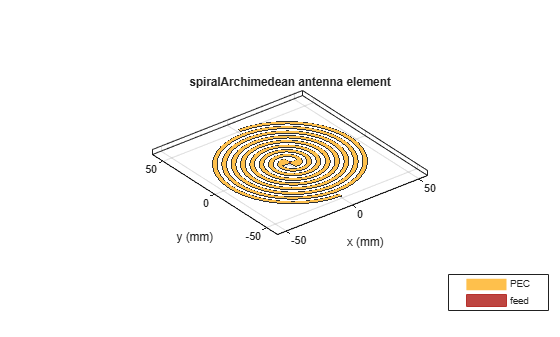
Create an Archimedean spiral antenna using the parameters defined.
sp = spiralArchimedean(Turns=turns,InnerRadius=Ri,OuterRadius=Ro);
figure
show(sp);
Impedance Behavior of Archimedean Spiral Antenna
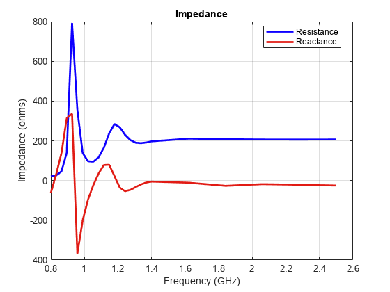
The impedance behavior of the spiral antenna shows multiple resonances at the low frequency band, before achieving a relatively constant resistance and reactance behavior. To capture these resonances we split the entire frequency band into two subbands. In the lower-frequency band, we sample with a finer spacing, while at the higher frequencies we opt for coarser spacing.
Nf1 = 20;
Nf2 = 6;
fband1 = linspace(0.8e9,1.4e9,Nf1);
fband2 = linspace(1.4e9,2.5e9,Nf2);
freq = unique([fband1,fband2]);
figure
impedance(sp, freq);
Reflection Coefficient
The input impedance of this spiral antenna can be obtained using the Booker's extension of the Babinet's principle for complementary structures [2]. For an antenna in free space, its input impedance equals 60 = 188.5 . This value is very close to the value of the impedance observed at the higher frequencies in the plot seen above. The reflection coefficient is calculated using the reference impedance of 188 . From the plot below it is seen that the present antenna is well matched for frequencies higher than 1.1 GHz.
S = sparameters(sp, freq, 188);
figure
rfplot(S);
title("Reflection Coefficient");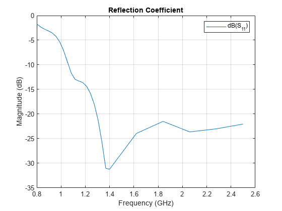
This matched frequency is higher than the approximate theoretical result of 0.96 GHz [1] since the current still reaches spiral tips as seen in the computational figure that follows.
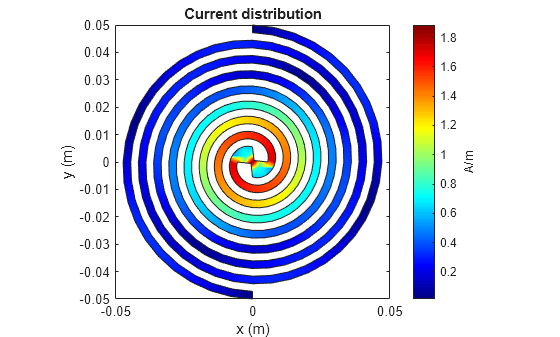
Current Distribution
The surface current distribution at low frequencies is:
figure
current(sp, 0.85e9);
view(0,90);
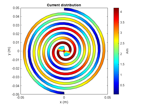
At higher frequencies, surface currents decay long before reaching the spiral tips. This results in a better matching.
figure
current(sp, 1.9e9);
view(0,90);
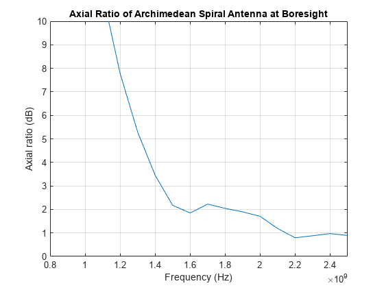
Axial Ratio
The current distribution presents a 180-degree rotational symmetry, which produces a circularly polarized radiated wave. The plot below shows the axial ratio at broadside of the spiral antenna. Observe that the spiral antenna achieves a good circular polarization for frequencies higher than 1.4 GHz.
freq = 0.8e9:100e6:2.5e9;
AR = zeros(size(freq));
for m = 1:numel(freq)
    AR(m) = axialRatio(sp, freq(m), 0, 90);
end
figure
plot(freq, AR);
grid on;
axis([0.8e9 2.5e9 0 10]);
xlabel("Frequency (Hz)");
ylabel("Axial ratio (dB)");
title("Axial Ratio of Archimedean Spiral Antenna at Boresight");
Discussion on the Results
Thesis [1] designs an Archimedean spiral antenna and compares its performance to theoretical results as well as to the commercially available EM solvers. The results obtained using the Antenna Toolbox™ match very well with the results presented in [1].
Reference
[1] Hinostroza,Israel "Conception de reseaux large bande d'antennes spirales", Other, Supelec, 2013 , pp. 58-62. Online at: https://theses.hal.science/file/index/docid/830469/filename/Hinostroza_Israel_final_final_thesis_2013.pdf
[2] Balanis, Constantine A. Antenna Theory: Analysis and Design. Fourth edition. Hoboken, New Jersey: Wiley, 2016.