Integer Delay (Obsolete)
Delay input by integer number of sample periods
Library
dspobslib
Description
Note
The Integer Delay block will be removed from the product in a future release. We strongly recommend replacing this block with the Delay block.
The Integer Delay block delays a discrete-time input by the number of sample intervals specified in the Delay parameter. Noninteger delay values are rounded to the nearest integer, and negative delays are clipped at 0.
Sample-Based Operation
When the input is a sample-based M-by-N matrix, the block treats each of the M*N matrix elements as an independent channel. The Delay parameter, v, can be an M-by-N matrix of positive integers that specifies the number of sample intervals to delay each channel of the input, or a scalar integer by which to equally delay all channels.
For example, when the input is M-by-1 and v
is the matrix [v(1) v(2) ... v(M)]', the first channel is delayed
by v(1) sample intervals, the second channel is delayed by
v(2) sample intervals, and so on. Note that when a channel is
delayed for Δ sample-time units, the output sample at time t
is the input sample at time t – Δ. When t – Δ is negative, then the output is the corresponding value specified
by the Initial conditions parameter.
A 1-D vector of length M is treated as an M-by-1 matrix, and the output is 1-D.
The Initial conditions parameter specifies the output of the block during the initial delay in each channel. The initial delay for a particular channel is the time elapsed from the start of the simulation until the first input in that channel is propagated to the output. Both fixed and time-varying initial conditions can be specified in a variety of ways to suit the dimensions of the input.
Fixed Initial Conditions
A fixed initial condition in sample-based mode can be specified as one of the following:
Scalar value to be repeated at each sample time of the initial delay (for every channel). For a 2-by-2 input with the parameter settings below,

the block generates the following sequence of matrices at the start of the simulation,
where is the i,jth element of the kth matrix in the input sequence.
Array of size M-by-N-by-d. In this case, you can set different fixed initial conditions for each element of a sample-based input. This setting is explained further in the Array bullet in Time-Varying Initial Conditions.
Initial conditions cannot be specified by full matrices.
Time-Varying Initial Conditions
A time-varying initial condition in sample-based mode can be specified in one of the following ways:
Vector of length d, where d is the maximum value specified for any channel in the Delay parameter. The vector can be a L-by-d, 1-by-d, or 1-by-1-by-d. The d elements of the vector are output in sequence, one at each sample time of the initial delay.
For a scalar input and the parameters shown below,
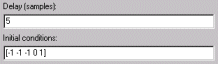
the block outputs the sequence
-1, -1, -1, 0, 1,...at the start of the simulation.Array of dimension M-by-N-by-d, where d is the value specified for the Delay parameter (the maximum value when the Delay is a vector) and M and N are the number of rows and columns, respectively, in the input matrix. The d pages of the array are output in sequence, one at each sample time of the initial delay. For a 2-by-3 input, and the parameters below,
the block outputs the matrix sequence
at the start of the simulation. Note that setting Initial conditions to an array with the same matrix for each entry implements constant initial conditions; a different constant initial condition for each input matrix element (channel).
Initial conditions cannot be specified by full matrices.
Frame-Based Operation
When the input is a frame-based M-by-N matrix, the block treats each of the N columns as an independent channel, and delays each channel as specified by the Delay parameter.
For frame-based inputs, the Delay parameter can be a scalar integer by which to equally delay all channels. It can also be a 1-by-N row vector, each element of which serves as the delay for the corresponding channel of the N-channel input. Likewise, it can also be an M-by-1 column vector, each element of which serves as the delay for one of the corresponding M samples for each channel. The Delay parameter can be an M-by-N matrix of positive integers as well; in this case, each element of each channel is delayed by the corresponding element in the delay matrix. For instance, if the fifth element of the third column of the delay matrix was 3, then the fifth element of the third channel of the input matrix is always delayed by three sample-time units.
When a channel is delayed for Δ sample-time units, the output sample at time t is the input sample at time t – Δ. When t – Δ is negative, then the output is the corresponding value specified in the Initial conditions parameter.
The Initial conditions parameter specifies the output during the initial delay. Both fixed and time-varying initial conditions can be specified. The initial delay for a particular channel is the time elapsed from the start of the simulation until the first input in that channel is propagated to the output.
Fixed Initial Conditions
The settings shown below specify fixed initial conditions. The value entered in the Initial conditions parameter is repeated at the output for each sample time of the initial delay. A fixed initial condition in frame-based mode can be one of the following:
Scalar value to be repeated for all channels of the output at each sample time of the initial delay. For a general M-by-N input with the parameter settings below,
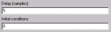
the first five samples in each of the N channels are zero. Notice that when the frame size is larger than the delay, all of these zeros are all included in the first output from the block.
Array of size 1-by-N-by-D. In this case, you can also specify different fixed initial conditions for each channel. See Time-Varying Initial Conditions for details.
Initial conditions cannot be specified by full matrices.
Time-Varying Initial Conditions
The following settings specify time-varying initial conditions. For time-varying initial conditions, the values specified in the Initial conditions parameter are output in sequence during the initial delay. A time-varying initial condition in frame-based mode can be specified in the following ways:
Vector of length D, where each of the N channels have the same initial conditions sequence specified in the vector. D is defined as follows:
When an element of the delay entry is less than the frame size,
D = d + 1
where d is the maximum delay.
When the all elements of the delay entry are greater than the input frame size,
D = d +
input frame
                                    size
- 1
Only the first d entries of the initial condition vector are used; the rest of the values are ignored, but you must include them nonetheless. For a two-channel ramp input
[1:100;
                            1:100]'
with a frame size of 4 and the parameter settings below,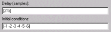
the block outputs the following sequence of frames at the start of the simulation.
Note that since one of the delays, 2, is less than the frame size of the input, 4, the length of the Initial conditions vector is the sum of the maximum delay and 1 (5+1), which is 6. The first five entries of the initial conditions vector are used by the channel with the maximum delay, and the rest of the entries are ignored. Since the first channel is delayed for less than the maximum delay (2 sample time units), it only makes use of two of the initial condition entries.
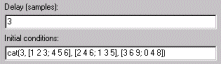
Array of size 1-by-N-by-D, where D is defined in Time-Varying Initial Conditions. In this case, the kth entry of each 1-by-N entry in the array corresponds to an initial condition for the kth channel of the input matrix. Thus, a 1-by-N-by-D initial conditions input allows you to specify different initial conditions for each channel. For instance, for a two-channel ramp input
[1:100;
                            1:100]'
with a frame size of 4 and the parameter settings below,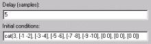
the block outputs the following sequence of frames at the start of the simulation.
Note that the channels have distinct time varying initial conditions; the initial conditions for channel 1 correspond to the first entry of each length-2 row vector in the initial conditions array, and the initial conditions for channel 2 correspond to the second entry of each row vector in the initial conditions array. Only the first five entries in the initial conditions array are used; the rest are ignored.
The 1-by-N-by-D array entry can also specify different fixed initial conditions for every channel; in this case, every 1-by-N entry in the array would be identical, so that the initial conditions for each column are fixed over time.
Initial conditions cannot be specified by full matrices.
Resetting the Delay
The block resets the delay whenever it detects a reset event at the optional Rst port. The reset sample time must be a positive integer multiple of the input sample time.
You specify the reset event in the Reset port parameter:
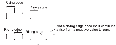
Nonedisables the Rst port.Rising edge— Triggers a reset operation when the Rst input does one of the following:Rises from a negative value to a positive value or zero
Rises from zero to a positive value, where the rise is not a continuation of a rise from a negative value to zero (see the following figure)
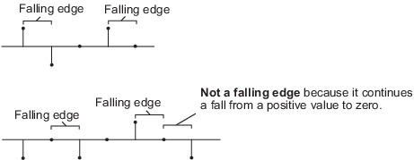
Falling edge— Triggers a reset operation when theRstinput does one of the following:Falls from a positive value to a negative value or zero
Falls from zero to a negative value, where the fall is not a continuation of a fall from a positive value to zero (see the following figure)
Either edge— Triggers a reset operation when theRstinput is aRising edgeorFalling edge(as described above).Non-zero sample— Triggers a reset operation at each sample time that theRstinput is not zero.Note
When running simulations in the Simulink®
MultiTaskingmode, sample-based reset signals have a one-sample latency, and frame-based reset signals have one frame of latency. Thus, there is a one-sample or one-frame delay between the time the block detects a reset event, and when it applies the reset. For more information on latency and the Simulink tasking modes, see Excess Algorithmic Delay (Tasking Latency) and Time-Based Scheduling and Code Generation (Simulink Coder).
Parameters
- Delay
The number of sample periods to delay the input signal.
- Initial conditions
The value of the block's output during the initial delay.
- Reset port
Determines the reset event that causes the block to reset the delay. For more information, see Resetting the Delay.
Supported Data Types
Double-precision floating point
Single-precision floating point
Fixed point (signed only)
Boolean — The block accepts Boolean inputs to the Rst port, which is enabled by the Reset port parameter.
8-, 16-, and 32-bit signed integers
8-, 16-, and 32-bit unsigned integers
See Also
| Unit Delay (Simulink) | Simulink |
| Variable Fractional Delay | DSP System Toolbox |
| Variable Integer Delay (Simulink) | Simulink |
Version History
Introduced in R2008b