Field-Oriented Control
This topic explains field-oriented control (FOC), a technique commonly used to control Permanent Magnet Synchronous Motors (PMSMs) and AC induction motors (ACIMs). As a form of vector control, FOC expresses currents, voltages, and magnetic fluxes in the motor as space vectors inside the d-q rotating reference frame. For more details about the vector control technique, see Closed-Loop Motor Control.
Using real-time plant feedback, FOC ensures optimal and precise control of motor speed and torque, even at low speeds. Because FOC automatically compensates for internal and external disturbances, such as changes in motor load, speed, or direction, it provides excellent dynamic response. In addition, FOC reduces torque ripples, resulting in smoother operation.
You can use FOC in applications where efficient and precise control is crucial, such as in electrical vehicles, industrial drives, robotics, aerospace, and wind turbines.
Field-Oriented Control Algorithm
FOC uses the Clarke transform to convert the three-phase currents to the α-β stationary reference frame. It then uses the Park transform to convert the currents to the rotating d-q reference frame, where the currents are represented by DC signals. The figures below illustrate normalized time-domain phase currents in the three frames.
Controlling motor phase AC currents directly using PI controllers results in a delayed tracking response because of the limited ability to use higher gains for reducing the steady state error. However, using d-q equivalents of motor phase currents and voltages increases control efficiency and performance with the PI controllers. Since integral control leads to minimum steady-state error and a very high DC gain, PI controllers show very high efficiency when controlling DC signals.
The FOC algorithm takes advantage of this efficiency by using PI controllers to control the d-q axis currents (control inputs) and generate the d-q axis voltage outputs (control signals) with zero steady-state error. The algorithm then uses mathematical transforms to convert these voltages into duty cycles for the inverter, which then drives the motor by using the corresponding three-phase voltages.
The FOC algorithm synchronizes the rotating d-q reference frame with the three-phase stator voltages, so that both have identical frequency and position. For synchronous machines like PMSMs, the stator and rotor fluxes are aligned. Therefore, you can align the d-q reference frame with the stator voltages by orienting the d-axis with the rotor flux. To perform this orientation, FOC requires the rotor position, which you can obtain using physical position sensors or sensorless position estimation algorithms. For details on these techniques, see Modeling Field-Oriented Control Algorithm.
FOC independently controls the magnitude and phase of stator currents so that the rotor matches the reference control input. To achieve precise control over motor speed and torque, the algorithm decouples stator magnetic flux (driven by q-axis current) and torque (driven by d-axis current) components. The algorithm controls flux and torque independently by varying the currents along d- and q-axes. With d-axis aligned with rotor’s magnetic field, you can generate maximum torque by minimizing d-axis current (stator magnetic flux) and maximizing q-axis current.
Modeling Field-Oriented Control Algorithm
The FOC algorithm uses two PI controllers to independently control d-axis and q-axis currents. These PI controllers supply d-q axes voltages as control signals. The algorithm then uses the inverse Park transform to convert these voltages into their α-axis and β-axis equivalents in the stationary orthogonal reference frame. FOC uses a modulation technique, such as PWM modulation, that uses these voltages to generate the duty cycles to drive the inverter.
Transforming the currents to the d-q axes requires rotor mechanical position feedback, which you can obtain using position sensors or sensorless position estimators.
Physical position sensors such as quadrature encoders, resolvers, and Hall effect sensors detect motor mechanical position information, which you can decode using these Motor Control Blockset™ blocks:
Sensorless position estimators use electrical measurements on the stator to estimate the electrical position of the motor. Motor Control Blockset provides the following sensorless position estimators:
The FOC algorithm uses rotor position to compute the motor speed feedback.
In addition to the d-axis and q-axis PI current controllers that form the inner current control loop, FOC uses an outer speed control loop with a separate PI controller (at a lower sampling frequency) to control the motor speed. The speed control loop is cascaded with the torque control loop. It accepts a speed reference as the control input and uses the motor speed feedback to generate d-axis and q-axis reference currents. These reference currents generate the reference torque optimally, and act as control inputs for the current controllers. Therefore, by running a speed controller at a lower rate alongside the current controllers, an FOC algorithm can follow both a speed and torque reference.
In your algorithm, you can model the lag during current measurement using sampling delays. Similarly, you can use a delay to model the computation time needed to execute the control algorithm.
Permanent Magnet Synchronous Motor
The following figure shows the FOC architecture for a PMSM. For a detailed set of equations and assumptions that Motor Control Blockset uses to implement FOC for a PMSM, see Mathematical Model of PMSM.
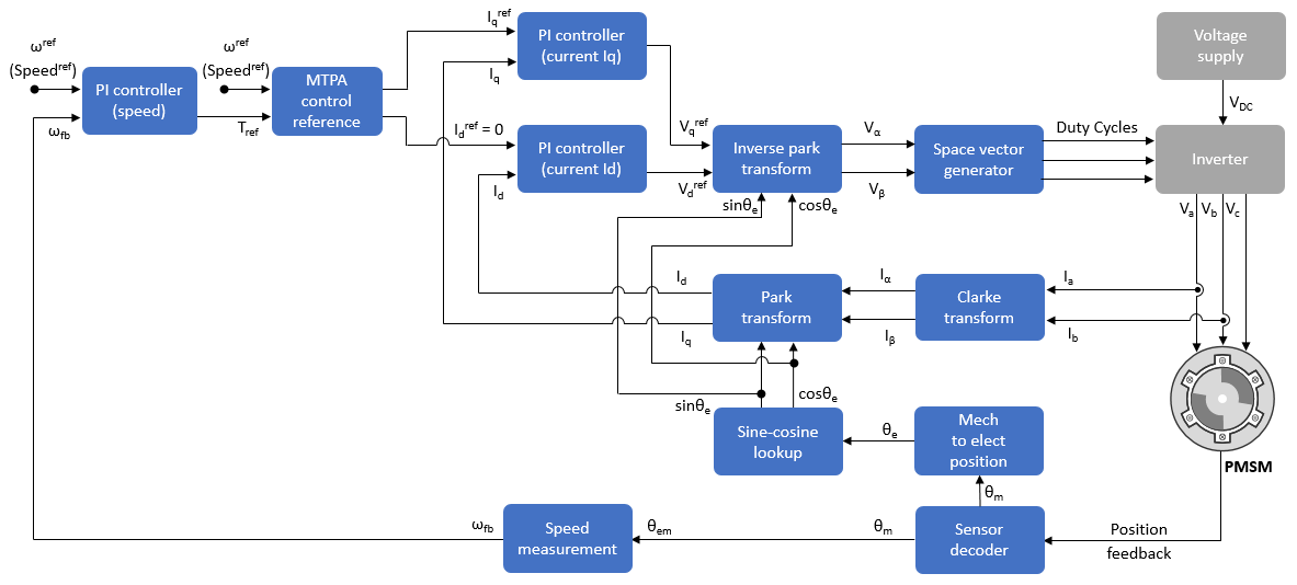
Because the inner current control loop is primarily used to control torque, the FOC algorithm for a surface-mount PMSM (SPMSM) usually uses a zero-flux reference. Therefore, when modeling FOC for an SPMSM, you can set the d-axis current to zero and use a maximum value for the q-axis current reference to maximize the generated torque.
However, when modeling FOC for an interior PMSM (IPMSM), you can take advantage of the higher motor saliency by adjusting both d-axis and q-axis current references to maximize the generated torque.
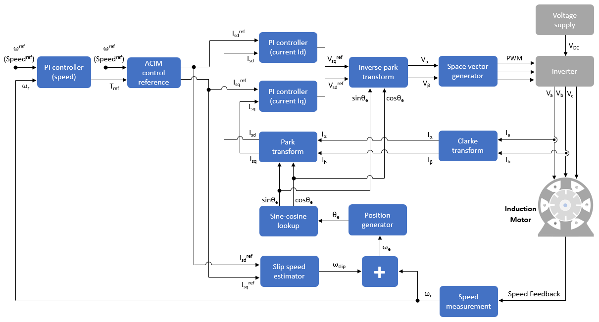
AC Induction Motor
The following figure shows the FOC architecture for an AC induction motor (ACIM). For a detailed set of equations and assumptions that Motor Control Blockset uses to implement FOC of an induction motor, see Mathematical Model of Induction Motor.
Tuning Controller Gains
PI controller gains act as control parameters that determine the responsiveness, accuracy, and stability of the control system. For accurate results, you must tune these gains appropriately. You can use these techniques to determine the PI controller gains:
Tune controller gains using the Field Oriented Control Autotuner block. See Tune PI Controllers Using Field Oriented Control Autotuner.
Tune controller gains using Motor Control Blockset utility functions. See Estimate Control Gains and Tune Control Parameters.
Tune controller gains using the PID Tuner app.
Tune controller gains using online frequency response estimation (FRE). See Online Frequency Response Estimation Basics (Simulink Control Design).
For more details about the solutions provided by Motor Control Blockset™ for tuning the controller gains, see Gain Calculation and Tuning.
See Also
Topics
- Open-Loop and Closed-Loop Motor Control Techniques
- Field-Weakening Control
- Field-Oriented Control of PMSM Using Hall Sensor
- Field-Oriented Control of PMSM Using Quadrature Encoder
- Field-Oriented Control of Induction Motor Using Speed Sensor
- Sensorless Field-Oriented Control of PMSM
- Sensorless Field-Oriented Control of Induction Motor