phased.MVDREstimator2D
2-D MVDR (Capon) spatial spectrum estimator
Description
The MVDREstimator2D object computes a 2-D minimum variance
distortionless response (MVDR) spatial spectrum estimate. This DOA estimator is also referred to
as a Capon estimator.
To estimate the spatial spectrum:
Create the
phased.MVDREstimator2Dobject and set its properties.Call the object with arguments, as if it were a function.
To learn more about how System objects work, see What Are System Objects?
Creation
Description
estimator = phased.MVDREstimator2Destimator. The object estimates the spatial spectrum of the
signal using a narrowband MVDR beamformer.
estimator = phased.MVDREstimator2D(Name=Value)estimator, with each specified property
Name set to the specified Value. You can specify
additional name-value arguments in any order as
(Name1=Value1,...,NameN=ValueN).
Properties
Usage
Description
[
additionally returns Y,ANG] = estimator(X)ANG which represents the signal’s direction of
arrival (DOA) when the DOAOutputPort property is
true.
Note
The object performs an initialization the first time the object is executed. This
initialization locks nontunable properties
and input specifications, such as dimensions, complexity, and data type of the input data.
If you change a nontunable property or an input specification, the System object issues an error. To change nontunable properties or inputs, you must first
call the release method to unlock the object.
Input Arguments
Output Arguments
Object Functions
To use an object function, specify the
System object as the first input argument. For
example, to release system resources of a System object named obj, use
this syntax:
release(obj)
Examples
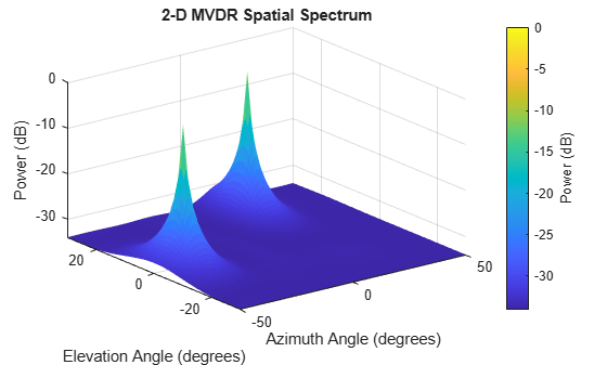
Estimate the DOAs of two signals received by a 50-element URA with a rectangular lattice. The antenna operating frequency is 150 MHz. The actual direction of the first signal is −37° in azimuth and 0° in elevation. The direction of the second signal is 17° in azimuth and 20° degrees in elevation. Then, plot the spatial spectrum.
Create the arriving signals.
fs = 8000;
t = (0:1/fs:1).';
x1 = cos(2*pi*t*300);
x2 = cos(2*pi*t*400);
array = phased.URA(Size=[5 10],ElementSpacing=[1 0.6]);
array.Element.FrequencyRange = [100e6 300e6];
fc = 150e6;
x = collectPlaneWave(array,[x1 x2],[-37 0;17 20]',fc);
Add noise.
noise = 0.1*(randn(size(x))+1i*randn(size(x)));
Create the MVDR DOA estimator and estimate the DOAs.
estimator = phased.MVDREstimator2D(SensorArray=array, ...
    OperatingFrequency=fc, ...
    DOAOutputPort=true,NumSignals=2, ...
    AzimuthScanAngles=-50:50, ...
    ElevationScanAngles=-30:30);
[~,doas] = estimator(x + noise);
Plot the spectrum.
plotSpectrum(estimator)
Estimate the DOAs of two signals received by a 50-element URA with a rectangular lattice. The antenna operating frequency is 150 MHz. The actual direction of the first signal is -37° in azimuth and 0° in elevation. The direction of the second signal is 17° in azimuth and 20° in elevation.
Create signals sampled at 8 kHz.
fc = 150e6;
fs = 8000;
t = (0:1/fs:1).';
x1 = cos(2*pi*t*300);
x2 = cos(2*pi*t*400);
array = phased.URA('Size',[5 10],'ElementSpacing',[1 0.6]);
array.Element.FrequencyRange = [100e6 300e6];
x = collectPlaneWave(array,[x1 x2],[-37 0;17 20]',fc);
Add complex noise.
noise = 0.1*(randn(size(x))+1i*randn(size(x)));
Create the MVDR DOA estimator for URA.
estimator = phased.MVDREstimator2D(SensorArray=array,...
    OperatingFrequency=fc,...
    DOAOutputPort=true,NumSignals=2,...
    AzimuthScanAngles=-50:50,...
    ElevationScanAngles=-30:30);
Use the step method to the DOA estimates.
[~,doas] = estimator(x + noise)
doas = 2×2

    17   -37
    20     0
Plot the spectrum.
plotSpectrum(estimator)

Algorithms
References
[1] Van Trees, H. Optimum Array Processing. New York: Wiley-Interscience, 2002.
Extended Capabilities
Version History
Introduced in R2011a