Amplifier
Complex baseband model of amplifier with noise and nonlinearities
Libraries:
RF Blockset /
Idealized Baseband
Description
The Amplifier block generates a complex baseband model of an amplifier with thermal noise. This block provides four nonlinearity models and three options to specify noise representation.
Examples
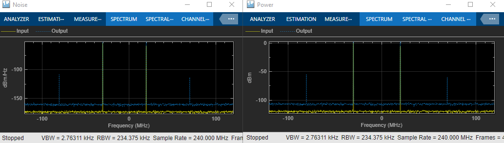
Idealized Baseband Amplifier with Nonlinearity and Noise
The example shows how to use the idealized baseband library Amplifier block to amplify a signal with nonlinearity and noise. The Amplifier uses the Cubic Polynomial model with a Linear power gain of 10 dB, an Input IP3 nonlinearity of 30 dBm, and a Noise figure of 3 dB.
Ports
Input
Input baseband signal, specified as a scalar, column, or matrix of a real or complex values.
Data Types: double | single
Output
Output baseband signal, returned as a scalar, column, or matrix of a real or complex
values. The output port mimics the properties of the input port. For example, if the input
baseband signal is specified as a real scalar with data type double, then
the output baseband signal is also specified as a real signal with data type
double.
Data Types: double | single
Parameters
Main Tab
Specify the amplifier nonlinearity model as one of the following:
poly— Use this model to concurrently model multiple nonlinear parameters within the idealized amplifier architecture. (since R2026a)cubic— Use this model to determine the linear coefficient of a third‑order polynomial and either IP3, P1dB, or Psat to determine the third‑order coefficient. The cubic polynomial model uses linear power gain to determine the values.ampm— Use this model to apply an AM/AM–AM/PM lookup table for computing the amplifier power characteristics.modified-rapp— Use this model to apply a normalized transfer function to compute the amplifier power characteristics.saleh— Use this model to apply a normalized transfer function based on the Saleh formulation to compute the amplifier power characteristics.
For more information, see Nonlinearity Models in Idealized Amplifier Block.
Linear gain, specified as a scalar in dB.
Third order nonlinearity type, specified as IIP3,
OIP3, IP1dB, OP1dB,
IPsat, or OPsat.
Input third-order intercept point, specified as a real positive number in dBm.
Dependencies
To enable this parameter, set Model to
cubic and Type of Non-Linearity
to IIP3.
Output third-order intercept point, specified as a real positive number in dBm.
Dependencies
To enable this parameter, set either one of these:
Model to
cubicand Type of Non-Linearity toOIP3.Model to
poly
Input 1 dB compression point, specified as a real positive number in dBm.
Dependencies
To enable this parameter, set Model to
cubic and Type of Non-Linearity
to IP1dB.
Output 1 dB compression point, specified as a real positive number in dBm.
Dependencies
To enable this parameter, set either one of these:
Model to
cubicand Type of Non-Linearity toOP1dB.Model to
poly
Input saturation point, specified as a real positive number in dBm.
Dependencies
To enable this parameter, set either one of these:
Model to
cubicand Type of Non-Linearity toIPsat.Model to
poly
Output saturation point, specified as a positive real number in dBm.
Dependencies
To enable this parameter, set either one of these:
Model to
cubicand Type of Non-Linearity toOPsat.Model to
poly
Code generation– Simulate model using generated C code. The first time you run a simulation, Simulink® generates C code for the block. The C code is reused for subsequent simulations, as long as the model does not change. This option requires additional startup time, but the speed of the subsequent simulations is faster thanInterpreted execution.Interpreted execution– Simulate model using the MATLAB® interpreter. This option shortens startup time speed, but the speed of the subsequent simulations is slower thanCode generation. In this mode, you can debug the source code of the block.
This button plots the power characteristics based on the parameters specified on the Main tab.
For more information, see Plot Power Characteristics.
Table lookup entries specified as a real M-by-3 matrix. This table expresses the model output power dBm level in matrix column 2 and the model phase change in degrees in matrix column 3 as related to the absolute value of the input signal power of matrix column 1 for the AM/AM - AM/PM model. The column 1 input power must increase monotonically.
The interp1 function with the linear method is
employed to extrapolate and interpolate the data points specified in the lookup table.
Furthermore, for extrapolating input data points that are less than the smallest specified
input power value in the lookup table, the AM/AM extrapolation uses a slope of 1 and constant
phase value equal to the phase of the smallest input power.
Dependencies
To enable this parameter, set Model to
ampm.
Voltage output saturation level, specified as a real positive number in dBm.
Dependencies
To enable this parameter, set Model to
modified-rapp.
Magnitude smoothness factor for the modified-rapp amplifier
model AM/AM calculations, specified as a positive real number.
Dependencies
To enable this parameter, set Model to
modified-rapp.
Phase gain for the modified-rapp amplifier model AM/PM
calculations, specified as a real scalar in radians.
Dependencies
To enable this parameter, set Model to
modified-rapp.
Phase saturation for the modified-rapp amplifier model AM/PM
calculations, specified as a positive real number.
Dependencies
To enable this parameter, set Model to
modified-rapp.
Phase smoothness factor for the modified-rapp amplifier model
AM/PM calculations, specified as a positive real number or two-tuple vector.
Dependencies
To enable this parameter, set Model to
modified-rapp.
Scaling factor for input signal level for the saleh amplifier
model, specified as a nonnegative real number in dB.
Dependencies
To enable this parameter, set Model to
saleh.
AM/AM two-tuple conversion parameters for saleh amplifier
model, specified as a two-element vector of nonnegative real numbers.
Dependencies
To enable this parameter, set Model to
saleh.
AM/PM two-tuple conversion parameters for
saleh amplifier model, specified as a two-element vector of
nonnegative real numbers.
Dependencies
To enable this parameter, set Model to
saleh.
Scaling factor for output signal level for saleh amplifier
model, specified as nonnegative real number in dB.
Dependencies
To enable this parameter, set Model to
saleh.
Noise Tab
Select this parameter to add system noise to the input signal. Once you select this parameter, the parameters associated with the Noise tab are displayed.
Type of noise, specified as one of the following:
noise-temperature— Noise temperatureNF— Noise figurenoise-factor— Noise factor
For more information, see Thermal Noise Simulations in Idealized Amplifier Block.
Dependencies
To enable this parameter, select Include Noise.
Noise temperature to model noise in the amplifier, specified as a nonnegative real number in degrees (K).
Dependencies
To enable this parameter, select Include Noise and set
Specify noise type to
noise-temperature.
Noise figure to model noise in the amplifier, specified as a nonnegative real number in dB.
Dependencies
To enable this parameter, select Include Noise and set
Specify noise type to
NF.
Noise factor to model noise in the amplifier, specified as a positive integer scalar greater than or equal to 1.
Dependencies
To enable this parameter, select Include Noise and set
Specify noise type to
noise-factor.
Source of initial seed used to prepare the Gaussian random number noise generator, specified as one of the following:
auto— Automatically generate seeds for each amplifier instance using a random number generator. The reset method of the instance has no effect.user— Use the value specified in the Seed parameter to initialize the random number generator. The reset method resets the random number generator and uses the value specified in the Seed parameter to initialize it.
Seed to initialize the random number generator, specified as either:
Scalar — Specify the seed value as a scalar to enable all the RF channel have the same Seed value.
Row vector — Specify the seed value as a row vector to enable different seed for each channel (since R2026a)
Dependencies
To enable this parameter, select the Include Noise parameter
and set the the Seed source parameter
to user.
References
[1] Razavi, Behzad. “Basic Concepts “ in RF Microelectronics, 2nd edition, Prentice Hall, 2012.
[2] Rapp, C., “Effects of HPA-Nonlinearity on a 4-DPSK/OFDM-Signal for a Digital Sound Broadcasting System.” Proceedings of the Second European Conference on Satellite Communications, Liege, Belgium, Oct. 22-24, 1991, pp. 179-184.
[3] Saleh, A.A.M., “Frequency-independent and frequency-dependent nonlinear models of TWT amplifiers.” IEEE Trans. Communications, vol. COM-29, pp.1715-1720, November 1981.
[4] IEEE 802.11-09/0296r16. “TGad Evaluation Methodology.“ Institute of Electrical and Electronics Engineers.https://www.ieee.org/
[5] Kundert, Ken.“ Accurate and Rapid Measurement of IP2 and IP3,“ The Designer Guide Community, May 22, 2002.
Extended Capabilities
C/C++ Code Generation
Generate C and C++ code using Simulink® Coder™.
Version History
Introduced in R2020aConfigure the idealized Amplifier block with the poly
model type to concurrently model multiple nonlinear parameters within the idealized amplifier
architecture.
The Amplifier block now supports matrix inputs to enable the simulation of multiple independent RF channels concurrently within the Idealized Baseband simulation environment.
The following parameter values in the Amplifier block in the idealized baseband library have been renamed:
| Parameter | Values before R2024b | Values since R2024b |
|---|---|---|
| Model | Cubic polynomial | cubic |
AM/AM - AM/PM | ampm | |
Modified Rapp | modified-rapp | |
Saleh | saleh | |
| Specify noise type | Noise figure | NF |
Noise temperature | noise-temperature | |
Noise factor | noise-factor | |
| Seed source | Auto | auto |
User specified | user |
The following default values in the Amplifier block in the idealized baseband library have been changed:
| Parameter | Default Values Before R2024b | Default Values Since R2024b |
|---|---|---|
| Type of Non-linearity | IIP3 | OIP3 |
| Specify noise type | Noise temperature | NF |
When you open a model created before R2024b containing the Amplifier block, the software replaces the parameter names and values as shown in the table.
MATLAB Command
You clicked a link that corresponds to this MATLAB command:
Run the command by entering it in the MATLAB Command Window. Web browsers do not support MATLAB commands.
Select a Web Site
Choose a web site to get translated content where available and see local events and offers. Based on your location, we recommend that you select: .
You can also select a web site from the following list
How to Get Best Site Performance
Select the China site (in Chinese or English) for best site performance. Other MathWorks country sites are not optimized for visits from your location.
Americas
- América Latina (Español)
- Canada (English)
- United States (English)
Europe
- Belgium (English)
- Denmark (English)
- Deutschland (Deutsch)
- España (Español)
- Finland (English)
- France (Français)
- Ireland (English)
- Italia (Italiano)
- Luxembourg (English)
- Netherlands (English)
- Norway (English)
- Österreich (Deutsch)
- Portugal (English)
- Sweden (English)
- Switzerland
- United Kingdom (English)