Data Store Memory
Define data store
Libraries:
Simulink /
Signal Routing
Description
The Data Store Memory block defines and initializes a named shared data store, which is a memory region usable by Data Store Read and Data Store Write blocks that specify the same data store name.
The location of the Data Store Memory block that defines a data store determines which Data Store Read and Data Store Write blocks can access the data store:
If the Data Store Memory block is in the top-level system, Data Store Read and Data Store Write blocks anywhere in the model can access the data store.
If the Data Store Memory block is in a subsystem, Data Store Read and Data Store Write blocks in the same subsystem or in any subsystem below it in the model hierarchy can access the data store.
A Data Store Read or Data Store Write block defined inside a referenced model can access the data stored at a higher level in the model hierarchy.
To allow a Data Store Read or Data Store Write block to access the data stored at a higher level in the model hierarchy from inside a referenced model:
Place a Data Store Memory block inside the referenced model.
In the Data Store Memory block dialog box, select Data store reference.
Do not include a Data Store Memory block in a For Each subsystem.
Obtaining correct results from data stores requires ensuring that data store reads and writes occur in the expected order. For details, see:
You can use Simulink.Signal objects in addition
to, or instead of, Data Store Memory blocks to define data stores. A data
store defined in the base workspace with a signal object is a
global data store. Global data stores are accessible to every
model, including all referenced models. See Data Stores for more
information.
You can select a Data Store Read, Data Store Write, or
Data Store Memory block to highlight blocks related to it. To show a
related block in an open diagram or new tab, pause on the ellipsis that appears after
selection. Then, select Related Blocks
![]() from the action bar. When multiple blocks correspond
to the selected block, a list of related blocks opens. You can filter the list of
related blocks by entering a search term in the text box. After you select a related
block from the list, window focus goes to the open diagram or new tab that shows the
related block.
from the action bar. When multiple blocks correspond
to the selected block, a list of related blocks opens. You can filter the list of
related blocks by entering a search term in the text box. After you select a related
block from the list, window focus goes to the open diagram or new tab that shows the
related block.
String Support
The Data Store Memory block can accept and output string data type only
if the block is configured for the default value of the Initial
value parameter (0).
Examples
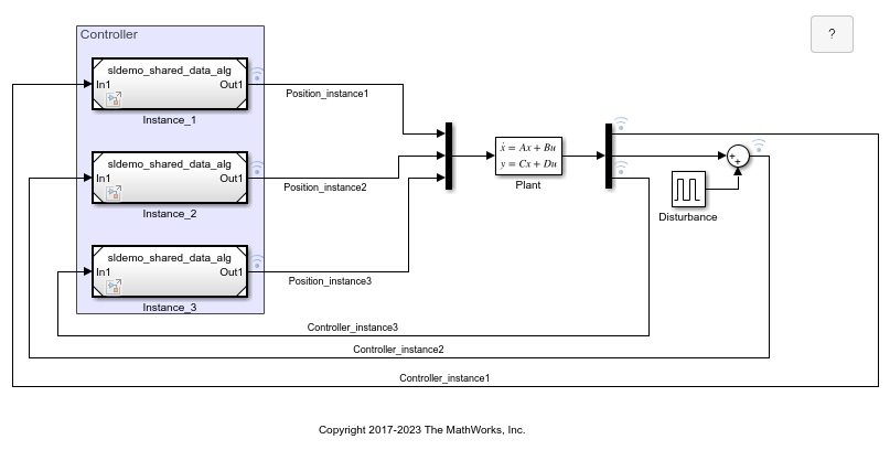
Share Data Among Multiple Instances of a Reusable Algorithm
Use a Data Store Memory block to share data among multiple instances of an algorithm in a model.
Access Data Store at Higher Level in Model Hierarchy
Access data store defined at a higher-level in the model hierarchy.
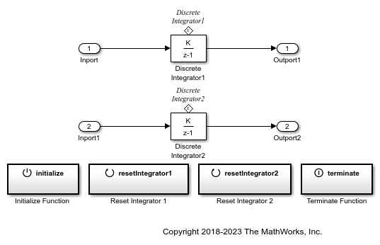
Initialize, Reset, and Terminate State of Simulink Block
Use the Initialize Function, Reset Function, and Terminate Function blocks to respond to events in a Simulink model.
Parameters
Main
Specify a name for the data store you are defining with this block. Data Store Read and Data Store Write blocks with the same name can read from, and write to, the data store initialized by this block. The name can represent a Data Store Memory block or a signal object defined to be a data store.
Programmatic Use
Block Parameter:
DataStoreName |
| Type: character vector |
Values: 'A' |
... |
Default:
'A' |
Rename this data store everywhere the Data Store Read and Data Store Write blocks use it in a model.
Limitations
You cannot use Rename All to rename a data store if you:
Use a
Simulink.Signalobject in a workspace to control the code generated for the data storeUse a
Simulink.Signalobject instead of a Data Store Memory block to define the data store
You must instead rename the corresponding
Simulink.Signal object from Model Explorer. For
an example, see Rename Data Store Defined by Signal Object.
Select this option when you need a subset of Simulink® blocks to access the elements of a Data Store Memory block defined at a higher level in the model hierarchy. These blocks include the Data Store Read block, Data Store Write block, S-Function block, MATLAB Function block, MATLAB System block, and Chart (Stateflow) block.
Programmatic Use
Block Parameter:
DataStoreReference |
Type: character
vector |
Values:
'off'|'on' |
Default:
'off' |
Limitations
When you select the Data store reference
parameter, these signal attributes are not supported:
Inherit for Data
type, -1 for
Dimensions and
auto for Signal
type.You must select these attributes
explicitly.
List all the Data Store Read and Data Store Write blocks that have the same data store name as the current block, and that are in the current system or in any subsystem below it in the model hierarchy. Clicking a block path displays and highlights that block in your model.
Signal Attributes
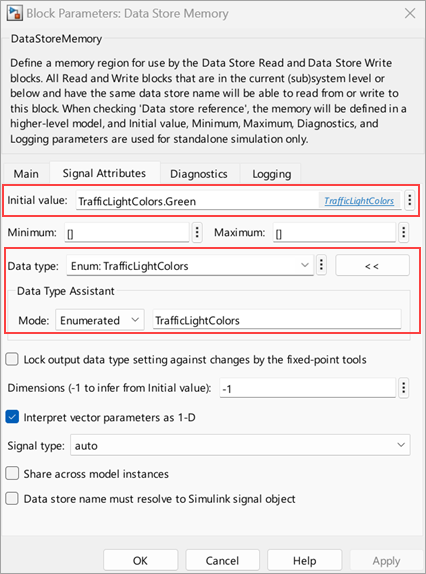
Specify the initial value or values of the data store. The Minimum parameter specifies the minimum value for this parameter, and the Maximum parameter specifies the maximum value.
If you specify a nonscalar value and set
Dimensions to -1 (the
default), the data store has the same dimensions as the array. Data that
you write to the data store (by using Data Store Write
blocks) must have these dimensions.
If you set the Dimensions parameter to a value
other than -1, the initial value dimensions must
match the dimensions that you specify, unless the initial value is a
scalar or a MATLAB® structure. If you specify a scalar, each element of the
data store uses the scalar as the initial value. Use this technique to
apply the same initial value (the scalar that you specify) to each
element without manually matching the dimensions of the initial value
with the dimensions of the data store.
To use this block to initialize a nonvirtual bus signal, specify the
initial value as a MATLAB structure and set the model configuration parameter Underspecified initialization detection to Simplified. For more information about
initializing nonvirtual bus signals using structures, see Specify Initial Conditions for Bus Elements.
For enumerated data type, the initial value must be a member of the enum class. For
example, you have an enum class TrafficLightColors
with three members Red, Yellow,
and Green. To specify Green as the
initial value, enter TrafficLightColors.Green in the
Initial value field.
Programmatic Use
Block Parameter:
InitialValue |
| Type: character vector |
| Values: scalar | vector | matrix | N-D array |
Default:
'0' |
Specify the minimum value that the block should output. The default
value is [] (unspecified). This number must be a
finite real double scalar value.
Note
If you specify a bus object as the data type for this block, do
not set the minimum value for bus data on the block. Simulink
ignores this setting. Instead, set the minimum values for bus
elements of the bus object specified as the data type. For
information on the Minimum property of a bus element, see Simulink.BusElement.
Simulink uses the minimum value to perform:
Parameter range checking (see Specify Minimum and Maximum Values for Block Parameters).
Simulation range checking (see Specify Signal Ranges).
Automatic scaling of fixed-point data types.
Optimization of the code that you generate from the model. This optimization can remove algorithmic code and affect the results of some simulation modes such as SIL or external mode. For more information, see Optimize using the specified minimum and maximum values (Embedded Coder).
Programmatic Use
Block Parameter:
OutMin |
| Type: character vector |
| Values: scalar |
Default: '[
]' |
Specify the maximum value that the block should output. The default
value is [] (unspecified). This number must be a
finite real double scalar value.
Note
If you specify a bus object as the data type for this block, do
not set the maximum value for bus data on the block. Simulink
ignores this setting. Instead, set the maximum values for bus
elements of the bus object specified as the data type. For
information on the Maximum property of a bus element, see Simulink.BusElement.
Simulink uses the maximum value to perform:
Parameter range checking (see Specify Minimum and Maximum Values for Block Parameters).
Simulation range checking (see Specify Signal Ranges).
Automatic scaling of fixed-point data types.
Optimization of the code that you generate from the model. This optimization can remove algorithmic code and affect the results of some simulation modes such as SIL or external mode. For more information, see Optimize using the specified minimum and maximum values (Embedded Coder).
Programmatic Use
Block Parameter:
OutMax |
| Type: character vector |
| Values: scalar |
Default: '[
]' |
Specify the output data type. You can set it to:
A rule that inherits a data type (for example,
Inherit: auto).The name of a built-in data type (for example,
single).The name of a data type object (for example, a
Simulink.NumericTypeobject).An expression that evaluates to a data type (for example,
fixdt(1,16,0)). Do not specify a bus object as the data type in an expression; useBus: <object name>to specify a bus data type.If you have Computer Vision Toolbox™, use the constructor for the
Simulink.ImageType(Computer Vision Toolbox) object and specify the properties to describe the image. By default, the data type uses theSimulink.ImageType(480,640,3)expression that represents the rows, columns, and channels of the image respectively.
The Data Type Assistant helps you set data
attributes. To use the Data Type Assistant, click ![]() . For more information, see Specify Data Types Using Data Type Assistant.
. For more information, see Specify Data Types Using Data Type Assistant.
Programmatic Use
Block Parameter:
OutDataTypeStr |
| Type: character vector |
Values:
'Inherit: auto' | 'double' | 'single' | 'half' | 'int8'
										| 'uint8' | 'int16' | 'uint16' | 'int32' | 'uint32' |
										'int64' | 'uint64' | 'boolean' | 'fixdt(1,16,0)' |
										'fixdt(1,16,2^0,0)' | 'string' | 'Enum: <class name>' |
'Simulink.ImageType(480,640,3)' |
Default:
'Inherit: auto' |
Select this parameter to prevent the fixed-point tools from overriding the Output data type you specify on the block. For more information, see Use Lock Output Data Type Setting (Fixed-Point Designer).
Programmatic Use
To set the block parameter value programmatically, use
the set_param function.
| Parameter: | LockScale |
| Values: | 'off' (default) | 'on' |
Dimensions of the data store. The default value,
-1, enables you to set the dimensions of the data
store by using the Initial value parameter.
However, in this case, you cannot use scalar expansion with the initial
value. You must specify the initial value by using an array that has the
dimensions that you want.
If you use a value other than -1, specify the same
dimensions as the dimensions of the Initial value
parameter, unless you specify the initial value as a scalar (for scalar
expansion) or a MATLAB structure. If the data store represents an array of buses,
and if you use a MATLAB structure for the initial value, you can specify
dimensions to initialize the array of buses with this structure.
Programmatic Use
Block Parameter:
Dimensions |
| Type: character vector |
| Values: scalar | vector | matrix |
Default:
'-1' |
Specify that the data store interpret vector initial values as one-dimensional.
By default, MATLAB represents vector data as matrices, which have two
dimensions. For example, MATLAB represents the vector [1 2 3] as a
1-by-3 matrix.
When you select this parameter, the data store represents vector data
by using only one dimension instead of two. For example, if you specify
an initial value of [1 2 3], the data store stores a
one-dimensional vector with three elements.
For more information, see Determine the Output Dimensions of Source Blocks.
Programmatic Use
Block Parameter:
VectorParams1D |
| Type: character vector |
Values: 'off' |
'on' |
Default:
'on' |
Specify the numeric type, real or complex, of the values in the data store.
Programmatic Use
Block Parameter:
SignalType |
| Type: character vector |
Values:
'auto' | 'real' | 'complex' |
Default:
'auto' |
In a single model reference hierarchy, when you use multiple Model blocks to refer to a model that contains a Data Store Memory block, by default, each instance of the referenced model (each Model block) reads from and writes to a separate copy of the data store. When you select Share across model instances, instead of interacting with a separate copy, all of the instances read from and write to the same data store.
When you set the model configuration parameter Code
interface packaging to Reusable
function to generate reentrant code from a model
(Simulink
Coder™), a data store with Share across model
instances selected appears in the code as a global symbol
that the generated entry-point functions access directly. For example, a
global symbol is a global variable or a field of a global structure
variable. Therefore, each call that your code makes to the entry-point
functions (each instance of the model) shares the data.
For an example, see Share Data Among Multiple Instances of a Reusable Algorithm. For more information, see Share Data Among Referenced Model Instances.
Programmatic Use
Block Parameter:
ShareAcrossModelInstances |
| Type: character vector |
Values:
'off' | 'on' |
Default:
'off' |
Specify that Simulink software, when compiling the model, searches the model and
base workspace for a Simulink.Signal object
having the same name, as described in Symbol Resolution. If
Simulink does not find such an object, the compilation stops with
an error. Otherwise, Simulink compares the attributes of the signal object to the
corresponding attributes of the Data Store Memory block. If the block
and the object attributes are inconsistent, Simulink halts model compilation and displays an error.
Programmatic Use
Block Parameter:
StateMustResolveToSignalObject |
| Type: character vector |
Values:
'off' | 'on' |
Default:
'off' |
Diagnostics
Select the diagnostic action to take if the model attempts to read data from a data store to which it has not written data in this time step. See also the Detect read before write diagnostic in the Data Store Memory block section of the Model Configuration Parameters > Diagnostics > Data Validity pane.
None— Produce no response.Warning— Display a warning and continue the simulation.Error— Terminate the simulation and display an error.
Programmatic Use
Block Parameter:
ReadBeforeWriteMsg |
| Type: character vector |
Values:
'none' | 'warning' | 'error' |
Default:
'warning' |
Select the diagnostic action to take if the model attempts to write data to the data store after previously reading data from it in the current time step. See also the Detect write after read diagnostic in the Data Store Memory block section of the Model Configuration Parameters > Diagnostics > Data Validity pane.
None— Produce no response.Warning— Display a warning and continue the simulation.Error— Terminate the simulation and display an error.
Programmatic Use
Block Parameter:
WriteAfterReadMsg |
| Type: character vector |
Values:
'none' | 'warning' | 'error' |
Default:
'warning' |
Select the diagnostic action to take if the model attempts to write data to the data store twice in succession in the current time step. See also the Detect write after write diagnostic in the Data Store Memory block section of the Model Configuration Parameters > Diagnostics > Data Validity pane.
None— Produce no response.Warning— Display a warning and continue the simulation.Error— Terminate the simulation and display an error.
Programmatic Use
Block Parameter:
WriteAfterWriteMsg |
| Type: character vector |
Values:
'none' | 'warning' | 'error' |
Default:
'warning' |
Logging
Select this option to save the values of this signal to the MATLAB workspace during simulation.
Programmatic Use
Block Parameter:
DataLogging |
| Type: character vector |
Values:
'off' | 'on' |
Default:
'off' |
Use this pair of controls, consisting of a list box and an edit field, to specify the name associated with logged signal data.
Simulink uses the signal name as its logging name by default. To
specify a custom logging name, select Custom
from the list box and enter the custom name in the adjacent edit
field.
Programmatic Use
Block Parameter:
DataLoggingNameMode |
| Type: character vector |
Values:
'SignalName' |
'Custom' |
Default:
'SignalName' |
If you set DataLoggingNameMode to
'Custom', you must specify the name
associated with logged signal data using the
DataLoggingName parameter.
Block Parameter:
DataLoggingName |
| Type: character vector |
| Values: character vector |
Default:
'' |
Discard all but the last N data points, where
N is the number that you enter in the adjacent
edit field. For more information, see Log Data Stores.
Programmatic Use
Block Parameter:
DataLoggingLimitDataPoints |
| Type: character vector |
Values:
'off' | 'on' |
Default:
'off' |
Block Parameter:
DataLoggingMaxPoints |
| Type: character vector |
| Values: nonzero integer |
Default:
'5000' |
Log every Nth data point, where
N is the number that you enter in the adjacent
edit field. For example, suppose that your model uses a fixed-step
solver with a step size of 0.1 s. If you select this
option and accept the default decimation value (2),
the software records data points for this signal at times
0.0, 0.2,
0.4, and so on. For more information, see Log Data Stores.
Programmatic Use
Block Parameter:
DataLoggingDecimateData |
| Type: character vector |
Values:
'off' | 'on' |
Default:
'off' |
Block Parameter:
DataLoggingDecimation |
| Type: character vector |
| Values: non-zero integer |
Default:
'2' |
Block Characteristics
Data Types |
|
Direct Feedthrough |
|
Multidimensional Signals |
|
Variable-Size Signals |
|
Zero-Crossing Detection |
|
Extended Capabilities
Version History
Introduced before R2006aSee Also
Data Store Read | Data Store Write
Topics
- Retrieve Data from Data Store Memory Blocks
- Data Stores
- Choose How to Define Data Stores
- C Data Code Interface Configuration for Model Interface Elements (Simulink Coder)
- Organize Parameter Data into a Structure by Using Struct Storage Class (Embedded Coder)
- Access Data Stores with Simulink Blocks
- Log Data Stores
- Code Generation for Data Store References (Simulink Coder)