Implement If-Else Logic in Simulink Models
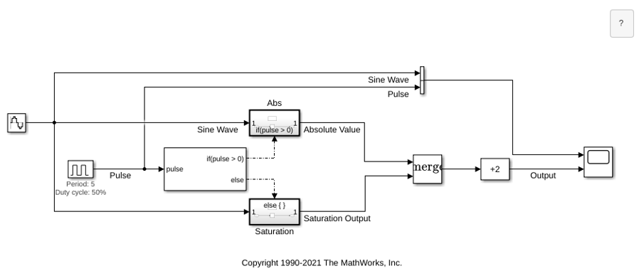
R2026bThis example shows how to implement if-else logic in Simulink® models. To implement if-else logic, use a combination of If and If Action Subsystem blocks. The If block evaluates logic conditions, and the corresponding If Action subsystem executes based on the evaluation outcome. In the model sldemo_ifsub, a set of arithmetic operations are performed on a sine wave. These operations execute based on logic conditions driven by a periodic pulse signal that transitions between zero and one.
Open the model.
If-Else Conditions
The If block implements the if-else conditions. These conditions compare the pulse wave signal value to zero and send action signals to the If Action Subsystem blocks.
Arithmetic Operations
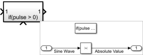
When the pulse signal is positive, the If block evaluates the if condition as true and activates the If Action Subsystem named Abs, which outputs the absolute value of the sine wave input signal.
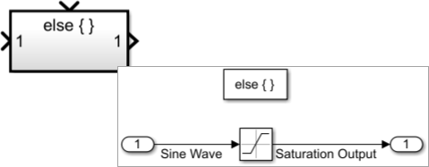
Otherwise, the pulse signal value is zero and the else condition activates the If Action Subsystem named Saturation. This subsystem either passes the sine wave as-is or clips it whenever the sine wave value exceeds the saturation limits specified in the Saturation block.
The outputs of the two subsystems are never active at the same time and are merged into one signal using a Merge block. The output signal is then biased by +2.
Simulation and Results
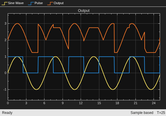
The scope shows the input sine wave signal, the pulse signal, and the output signal. When the pulse is on (indicated by a value of 1 ), the output is the absolute value of the sine wave. When the pulse is off (value 0 ), the subsystem either outputs the sine wave as-is or clips it whenever the sine wave value exceeds the limits specified in the Saturation block. In each case, the output is biased by +2.
See Also
If | If Action Subsystem | Pulse Generator | Merge | Bias

