Simulink.op.ModelOperatingPoint
Complete operating point of model in simulation
Description
A Simulink.op.ModelOperatingPoint object contains a complete
representation of the operating point of a model in simulation. Use the
Simulink.op.ModelOperatingPoint object to initialize a model to an
operating point for simulation. If you do not modify the model, simulations initialized using
model operating points produce the same results as an equivalent simulation with no initial
state specified.
For example, when you simulate a system that has a startup phase or initialization behavior, you can:
Simulate the model through the end of the startup or initialization phase.
Save the model operating point.
Run a set of simulations initialized to the model operating point at the end of the startup or initialization phase.
A model operating point contains:
Block state values, including hidden block states
The state of the solver and execution engine
Output values for some blocks
For more information, see Speed Up Simulation Workflows by Using Model Operating Points.
Creation
To get the operating point of a model, configure the model to save the final operating
point in simulation. The software creates a Simulink.op.ModelOperatingPoint
object when the simulation completes or when you pause or stop the simulation.
To configure a model to save the final operating point:
In the Simulink® Toolstrip, on the Modeling tab, click Model Settings.
On the Data Import/Export pane, select Final states and Save final operating point.
By default, the model operating point is returned as a property of the Simulink.SimulationOutput object returned by the simulation. If you disable the
Single simulation output configuration
parameter, the model operating point is saved in a workspace variable when you run the
simulation from a user interface, such as the Simulink Editor.
To specify the name of the Simulink.SimulationOutput property or
workspace variable that contains the model operating point, enter the name in the
Final States box.
You can also get the operating point of a model using either of these approaches:
When a simulation is paused, use the
get_paramfunction to get the current operating point of the model.op = get_param(mdl,"CurrentOperatingPoint");Configure the model to log operating points to a MAT file throughout the simulation. For details, see Save Model Operating Point During Simulation.
Properties
Object Functions
Examples
Open the model vdp.
mdl = "vdp";
open_system(mdl);
Configure the model to save the final operating point at the end of simulation.
On the Modeling tab, under Setup, click Model Settings.
In the Configuration Parameters dialog box, select the Data Import/Export pane.
On the Data Import/Export tab, select Final states and Save final operating point.
Click OK.
Alternatively, create a Simulink.SimulationInput object to store the parameter values for the simulation. Then, use the setModelParameter function to specify the parameter values to use in the simulation.
simIn = Simulink.SimulationInput(mdl);

simIn = setModelParameter(simIn,"SaveFinalState","on");
simIn = setModelParameter(simIn,"SaveOperatingPoint","on");
Set the stop time for the simulation to 10 seconds. On the Simulation tab, under Simulate, in the Stop Time box, enter 10, or use the setModelParameter function to specify the value of the StopTime parameter for the simulation.
simIn = setModelParameter(simIn,"StopTime","10");
Simulate the model.
out = sim(simIn);
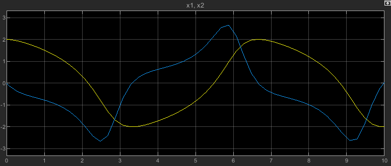
To view the simulation results, double-click the Scope block in the model. The plot in the Scope displays the values of the signals x1 and x2 over the 10-second simulation.
Resume the simulation by using the operating point you saved at the end of the first simulation as the initial operating point for the second simulation.
Get the final operating point from the first simulation from the Simulink.SimulationOutput object out.
vdpOP = out.xFinal;
Specify the operating point as the initial state for the simulation.
On the Modeling tab, under Setup, click Model Settings.
In the Configuration Parameters dialog box, on the Data Import/Export pane, select Initial state.
In the text box, enter
vdpOP.Click OK.
Alternatively, create another Simulink.SimulationInput object to configure this simulation. Then, use the setInitialState function to specify the initial state.
simIn2 = Simulink.SimulationInput(mdl);

simIn2 = setInitialState(simIn2,vdpOP);
Set the stop time for this simulation to 20. On the Simulation tab, under Simulate, in the Stop Time box, enter 20, or use the setModelParameter function to specify the value of the StopTime parameter for the simulation.
simIn2 = setModelParameter(simIn2,"StopTime","20");
Simulate the model again, resuming the prior simulation by starting this simulation from the final operating point saved in the first simulation.
out2 = sim(simIn2);
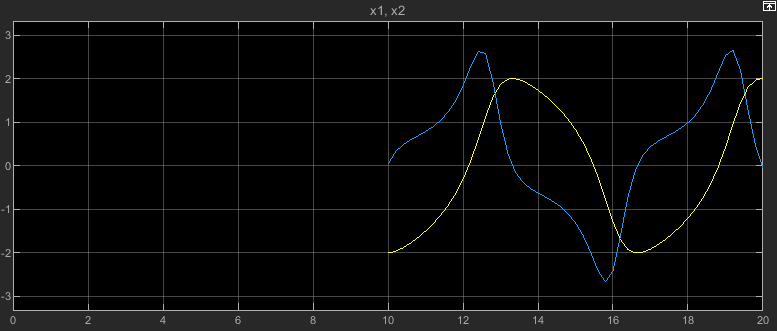
The plot in the Scope window updates to show the data from this simulation. The time axis starts at 0 and goes to the simulation stop time of 20. Because this simulation started from the initial operating point from the first simulation, which ended after 10 simulation seconds, the plot shows the values of the signals x1 and x2 only between simulation time 10 seconds and 20 seconds.
Tips
For best results, clear the Block reduction parameter before running a simulation that saves the final operating point. When you simulate a model from an initial operating point, the software disables the Block reduction configuration parameter. You might not be able to initialize simulations using an operating point if the Block reduction parameter is enabled in the simulation that creates the operating point.
When you specify an initial state as a model operating point:
The software uses the fixed step size in the operating point if the simulation uses a fixed-step solver and specifies the Fixed-step size (fundamental sample time) parameter as
auto.The software uses the maximum step size in the operating point if the simulation uses a variable-step solver and specifies the Max step size parameter as
auto.
To modify the operating point of a model reference in a simulation that runs from an initial operating point, specify the
InitialStateparameter of the Model block as aSimulink.op.ModelBlockOperatingPointobject. The Model block operating point overrides the operating point information for the block in theSimulink.op.ModelOperatingPointobject specified as the initial operating point of the top model.To initialize a simulation to a partial operating point, specify the initial operating point of one or more Model blocks without specifying an initial operating point for the top model.
Version History
Introduced in R2019aSee Also
Objects
Simulink.SimulationInput|Simulink.op.ModelBlockOperatingPoint|Simulink.SimulationData.Dataset|Simulink.SimulationData.State