PWM
R2026bGenerate pulse width modulated waveform on Teensy 4.0 and 4.1 output pins and enable PWM interrupts
Since R2026b
PWM Teensy4 block

To add a block to a model, double-click the canvas and start typing the block name. Then, select the block from the list.
Libraries:
Simulink Support Package for Arduino Hardware /
Advanced /
TEENSY4
Description
Add-On Required: This feature requires the Simulink Support Package for Arduino Hardware add-on.
The Teensy PWM block generates a pulse width modulated (PWM) square waveform on a specified PWM output pin for Arduino® compatible Teensy 4.0 and 4.1 boards.
Use this block to:
Drive loads such as motors or power stages using PWM duty cycle control.
Enable PWM overflow interrupts or compare match interrupts to synchronize control algorithms and acquisitions.
Configure alignment-related interrupt events (center, rising, and falling) for supported Teensy PWM channels.
Supported Arduino Boards
Teensy 4.0 (Arduino Compatible)
Teensy 4.1 (Arduino Compatible)
Examples
To drive a PWM pin and update the duty cycle over time, start by adding the Teensy PWM block to your model.
Add the Teensy PWM block to your model.
In the model settings, set Hardware board to either
Teensy 4.0 (Arduino Compatible) or
Teensy 4.1 (Arduino Compatible).
In the Teensy PWM block parameters, set Pin number to a PWM-capable Teensy pin.
At the Data input port, provide a signal between
0 and 1023. Run the model. Use an
oscilloscope to verify the duty cycle and frequency on the selected Teensy pin. If
the Data value changes with time, the duty cycle updates accordingly.
Generate an interrupt at the PWM period boundary by enabling the overflow interrupt on a Teensy PWM output. Then, trigger a function-call subsystem using the Teensy Hardware Interrupt block.
Add the Teensy PWM, Teensy Hardware Interrupt, and Function-Call Subsystem blocks to your model. Connect the function-call output of the Teensy Hardware Interrupt block to the trigger port of the Function-Call Subsystem.

In the model settings, set Hardware board to either
Teensy 4.0 (Arduino Compatible) or
Teensy 4.1 (Arduino Compatible).
In the Teensy PWM block, set Pin number to a PWM-capable Teensy pin. Identify the FlexPWM timer module associated with the selected pin. For more information, see Map PWM Pins to FlexPWM Timer Modules.
Enable Enable overflow/underflow (OVF) interrupt.
In the Teensy Hardware Interrupt block parameters, specify a value for the Interrupt group parameter.
Set Interrupt
name to the handler that corresponds to the FlexPWM module used by
the Teensy PWM block. For example, use
FLEXPWM2_0_Handler when the Teensy
PWM block is using a pin mapped to FlexPWM module 2, sub-channel 0. For
more information, see Map PWM Pins to FlexPWM Timer Modules.
In the Teensy Hardware Interrupt block parameters, in the Events to serve table, select the overflow event. For example, select FlexPWM2_0_Overflow to handle the PWM overflow interrupt.
To prevent preemption by other interrupts while servicing the PWM interrupt, enable Run interrupt service routine as atomic unit.
Generate interrupts at specific points in the PWM cycle (center, rising edge, and falling edge) by enabling compare match events on a Teensy PWM output and handling them using the Teensy Hardware Interrupt block.
Add the Teensy PWM, Teensy Hardware Interrupt, and Function-Call Subsystem blocks to your model. Connect the function-call output of the Teensy Hardware Interrupt block to the trigger port of the Function-Call Subsystem.
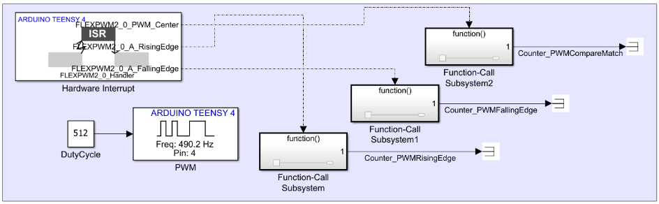
In the model settings, set Hardware board to either
Teensy 4.0 (Arduino Compatible) or
Teensy 4.1 (Arduino Compatible).
In the Teensy PWM block, set Pin number to a PWM-capable Teensy pin. Identify the FlexPWM timer module associated with the selected pin. For more information, see Map PWM Pins to FlexPWM Timer Modules.
Enable Enable compare match interrupt.
Select one or more match events:
In the Teensy Hardware Interrupt block parameters, specify a value for the Interrupt group parameter.
Set Interrupt
name to the handler that corresponds to the FlexPWM module used by
the Teensy PWM block. For example, use
FLEXPWM2_0_Handler when the Teensy
PWM block is using a pin mapped to FlexPWM module 2, sub-channel 0. For
more information, see Map PWM Pins to FlexPWM Timer Modules.
In the Events to serve table, select the required FlexPWM events. For example, select FlexPWM2_0_A_RisingEdge to handle the PWM rising-edge interrupt or FlexPWM2_0_A_FallingEdge to handle the PWM falling-edge interrupt.
To prevent preemption by other interrupts while servicing the PWM interrupt, enable Run interrupt service routine as atomic unit.
Extended Examples
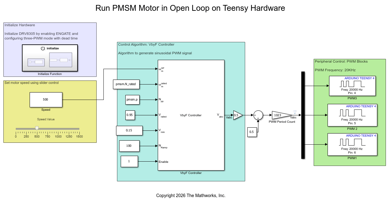
Run PMSM Motor in Open Loop on Teensy Hardware
Use Simulink® Support Package for Arduino® Hardware to run a permanent magnet synchronous motor (PMSM) using open-loop voltage-frequency (V/F) control on a Teensy® development board.
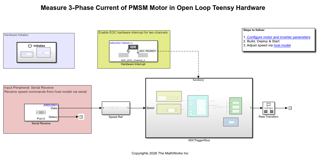
Measure Phase Currents of PMSM Motor in Open Loop Teensy Hardware
Use Simulink® Support Package for Arduino® Hardware to measure three-phase currents of a permanent magnet synchronous motor (PMSM). The example deploys an open-loop voltage-frequency (V/F) control algorithm on a Teensy® development board.
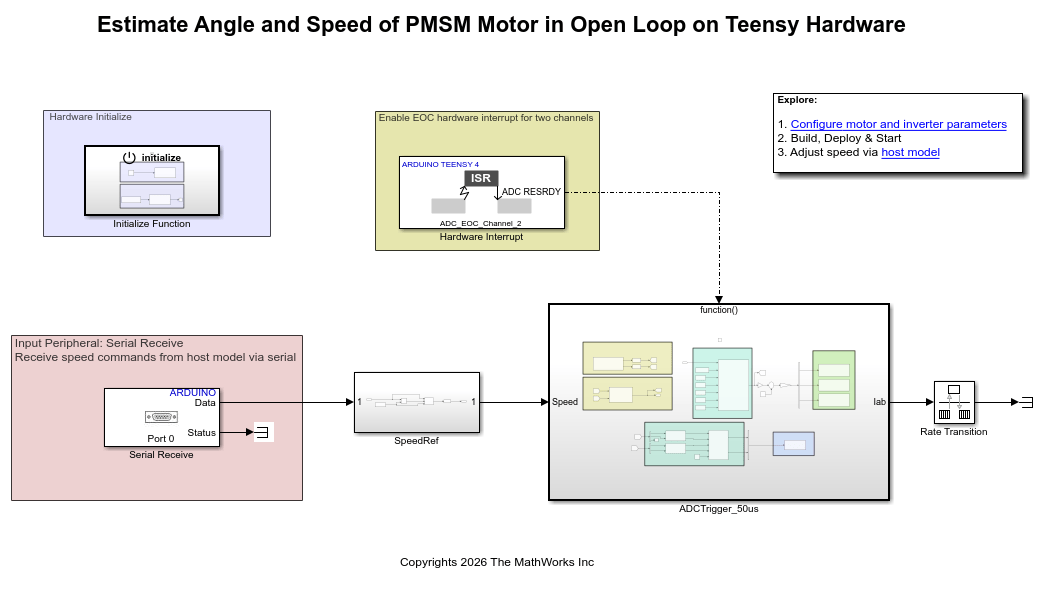
Estimate Angle and Speed of PMSM Motor in Open Loop on Teensy Hardware
Use Simulink® Support Package for Arduino® Hardware to estimate the rotor angle and speed of a permanent magnet synchronous motor (PMSM) using an extended EMF observer. The example deploys an open-loop voltage-frequency (V/F) control algorithm and the observer on a Teensy® development board.
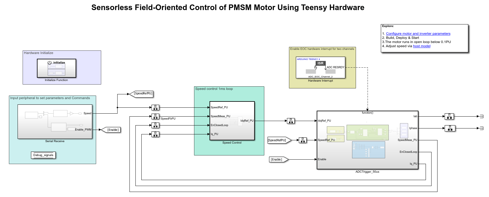
Sensorless Field-Oriented Control of PMSM Motor Using Teensy Hardware
Use Simulink® Support Package for Arduino® Hardware to implement a sensorless field-oriented control (FOC) of a permanent magnet synchronous motor (PMSM). The example deploys the control algorithm to a Teensy development board and drives the motor through the DRV8305EVM inverter.
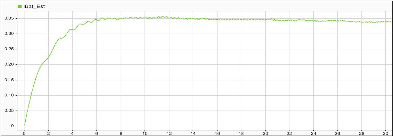
Estimate Battery Current of PMSM in Open-Loop Control Using Arduino Hardware
Use Simulink® Support Package for Arduino® Hardware to estimate the battery current of a permanent magnet synchronous machine (PMSM) in open-loop control using Motor Control Blockset™. This example also shows how to actuate a PMSM motor and calculate phase currents that are indirectly used to estimate the current of the battery.
Ports
Input
Parameters
More About
Teensy 4.0 and 4.1 boards route PWM output through multiple FlexPWM timer modules. Each FlexPWM module contains subchannels, and each subchannel maps to specific digital pins through two output paths: PWM_A and PWM_B. The pin mapping table shows these associations.
Use this table to:
Determine which FlexPWM timer module and sub-channel a given pin belongs to.
Identify which pins share the same timer and therefore the same PWM frequency.
Select the correct ADC trigger timer in the Teensy Analog Input block for PWM-synchronized ADC conversions.
Select the corresponding interrupt group in the Teensy Hardware Interrupt block for PWM interrupts.

Consider reading the table as follows:
Each table row represents a FlexPWM module and subchannel combination. For example, the FlexPWM2_0 row prescribes module 2, subchannel 0. The pin numbers listed in that row are the physical pins routed to that timer. The PWM_A or PWM_B outputs on the same subchannel share the same timer frequency but can have independent duty cycles. Use complementary PWM_A and PWM_B outputs when your application requires paired signals, such as H-bridge motor control.
Once you know the FlexPWM module for your pin:
Enter the pin number in the Pin number parameter of the Teensy PWM block.
To synchronize ADC conversions, set the ADC trigger timer parameter of the Teensy Analog Input block to the same FlexPWM module (for example,
FlexPWM2_0).To handle PWM interrupts, set the Interrupt group parameter of the Teensy Hardware Interrupt block to the matching FlexPWM group (for example,
PWM Interrupt FLEXPWM2_X).Do not assign the same pin number to multiple blocks within a model.
Extended Capabilities
Version History
Introduced in R2026b

