RC Receive
Reads radio control (RC) channel data from transmitter supported by ArduPilot
Since R2026a

Libraries:
UAV Toolbox Support Package for ArduPilot Autopilots /
Peripheral Blocks
Description
Add-On Required: This feature requires the UAV Toolbox Support Package for ArduPilot Autopilots add-on.
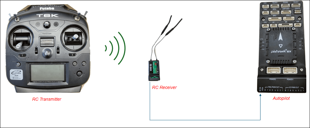
The RC Receive block acquires raw input data from selected channels of an RC transmitter. The block provides options to apply trim and deadzone adjustments for output normalization. Additionally, the block can output auxiliary information such as flight mode, radio signal strength indicator (RSSI), arming status, and motor emergency stop status.
Examples
Verify RC Transmitter Input with RC Receive Block
Use the UAV Toolbox Support Package for ArduPilot® Autopilots to test your RC transmitter with the RC Receive block in Simulink®. You can verify RC functionality on both the host target (simulation environment) and ArduPilot-based flight controller hardware. You also learn to read and interpret both raw and normalized channel data with trim and deadzone settings applied. Additionally, you monitor various vehicle statuses.
Limitations
This block is not supported in triggered subsystems.
Ports
Output
Parameters
More About
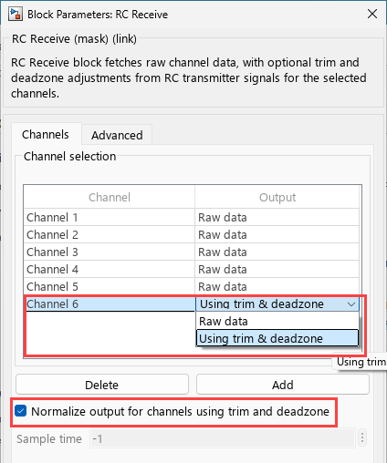
When you select Using trim & deadzone as the output
for a channel in the RC Receive block, the output is normalized based on the RC
channel's trim and deadzone settings.
Key Parameters
Here are the parameters used in the normalization calculation:
Key Parameters
| Parameter | Description |
|---|---|
radio_in | The raw input value from the RC transmitter for the channel. |
radio_trim | The trim (center) value of the RC channel. Set via the parameter
RCx_TRIM (where x = 1 to 16). |
dead_zone | The deadzone value, set via parameter RCx_DZ (e.g.,
RC1_DZ), which defines the range around the trim where
small movements are ignored. |
radio_min | The minimum value for the RC channel. |
radio_max | The maximum value for the RC channel. |
reversed | Boolean indicating if the channel is reversed. If the channel is reversed, this is true. |
reverse_mul | Multiplier, set to -1 if reversed, otherwise 1. |
Step-by-Step Calculation
The calculation proceeds as follows, with each step explained in detail:
Define Deadzone Boundaries:
dz_min = radio_trim - dead_zone
dz_max = radio_trim + dead_zone
Any input between
dz_minanddz_maxis considered "neutral" (output = 0).
Determine Output Based on Input:
Below Deadzone: If
radio_in < dz_minanddz_min > radio_minoutput = reverse_mul * (radio_in - dz_min) / (dz_min - radio_min)
Above Deadzone: If
radio_in > dz_maxandradio_max > dz_maxoutput = reverse_mul * (radio_in - dz_max) / (radio_max - dz_max)
Within Deadzone:
output = 0
Reverse Direction (if applicable):
If the channel is reversed,
reverse_mul = -1, otherwisereverse_mul = 1.
Constrain Output:
The output is constrained to the range [-1.0, 1.0]:
output = constrain_float(output, -1.0, 1.0)
If the value is more
1, then it is1and if the output is less than-1, it is-1.
What Happens When Not Normalized?
When Normalize output for channels using trim and deadzone option is not selected then the RC channel values are not adjusted for trim or deadzone and the formula is calculated using this formula:
trimDzChannelData = static_cast<int16_T>(minChVal + (normTrimDz + 1) * (maxChVal - minChVal) / 2);
This formula is used to convert the normalized RC channel value (which ranges from
-1 to 1) back to the actual channel value range
defined by the hardware (from minChVal to
maxChVal).
normTrimDz: This is the normalized value (from
-1to1) obtained from the previous calculation (see the earlier code block).minChVal and maxChVal: These are the minimum and maximum possible values for the channel (for example,
1000and2000for many RC systems).
This converts a normalized value (from -1 to 1)
back to the original PWM range.
When
normTrimDz=-1, the output isminChVal.When
normTrimDz=1, the output ismaxChVal.Values in between are linearly interpolated.
Version History
Introduced in R2026a