Latest Contributions
There’s a webinar on online learning tools with MATLAB this Friday. It’s for time zones in Asia Pacific.
Register if you’re interested!
"The model is configured to create a SIL block, which is not supported for the selected hardware board. To resolve this, search for 'Create block' in the Configuration Parameters dialog box and set it to 'None' or 'PIL'.
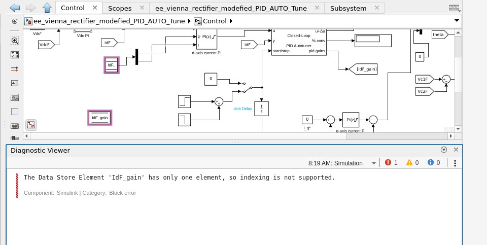
I am facing an issue in data store memory block using store memory Read and write Block in matlab simulink. I have attached the screen short in which the posed error has been depicted.
Hi, I am currently studying the effects of varying switching frequency towards the inverter and motor system efficiency. I am using the three-phase converter which the gate signal is sent by a PWM generator. Inside the PWM generator block, there is switching frequency parameter. Therefore, is it possible if I can tune the value of switching frequency by making it as input and receving the signal in Matlab Simulink similar with Vabc and Vdc instead of tuning from Matlab code?
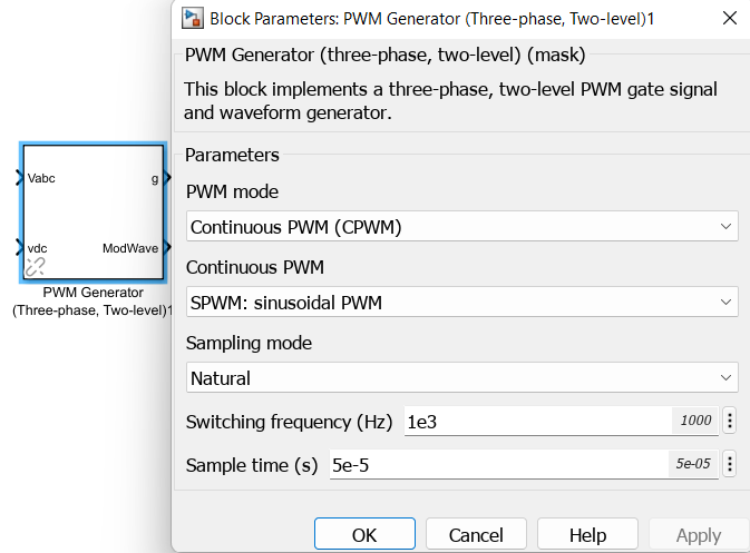
Hope to receive any comment or suggestion. Thank you.
Need some guidance on how to model the mutual inductance model from Simscape. The secondary side does not receive the voltage.
I am wondering what others use for those little short-cuts or niceties in MATLAB. I have in mind something you wrote or something somebody else wrote or an underused MW function.
Here are my two favorites.
This is a simple script I use. Here is the entire contents of CLC.m (yes, it is capitalized):
clear all,close all,clc
Very simple, but I use it all the time. Here is another one I use so often that I forget not every machine has it (though every machine should, IMO):
Here is an underused MW function that I occasionally employ when working on someone else's machine. The usual response is, "Wait, what did you just do?"
home
What are some of yours?
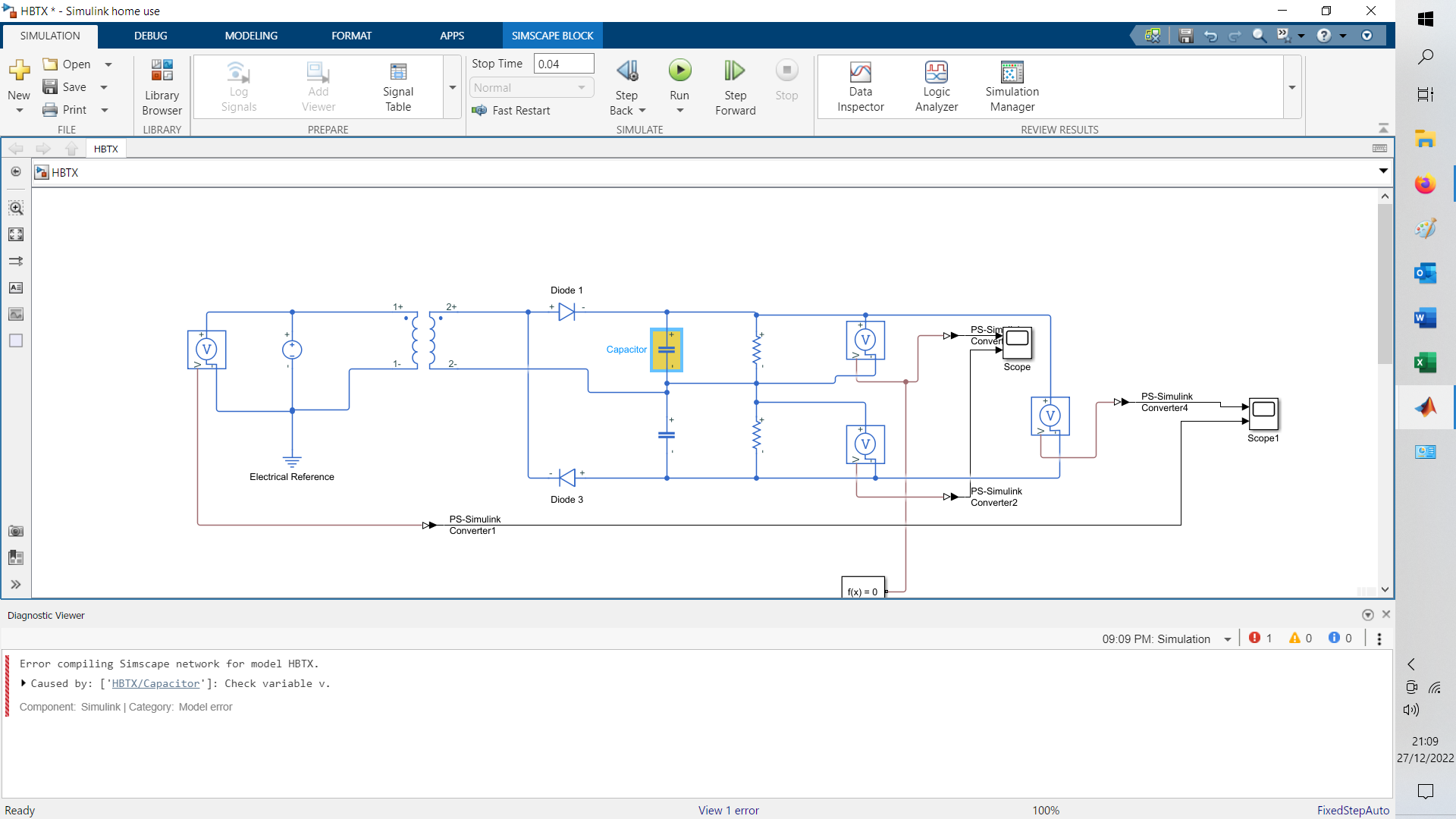
Hi, having problems with this model. Tried changing all the capacitor values without any success. Any help/suggestions would be most welcome.
Hello , I wonder how to determine continous or discrete time modelling.For example if I want to run my model in MCU in this case discrete model is suitable?I am a bit confused
Hi Fellow Users,
I am Muthuserpi From A begginer of Optics studio Please anyone help me how to add two diffeaction reflective grating and How to tilt and decenter in matlab simulation
Thanks And Regards
S.Muthuserpi
I want to understand this from the scratch, i will appreciate help and guidance very much.
Hello Community,
For E vehicle application to control the speed and torque of PMSM motor I am implementing FOC algorithm. We know that to arrive at Speed set point we have speed control loop which is outer loop, Further PI CONTROLLER of speed loop will give reference for Iq current which regulates the current using current loop. My question is 1.How to arrive at Torque set point?
2. Is speed control using FOC is enough or we should implement Torque control algorithm also?
3. should we have speed mode and Torque mode selection in case of constant speed requirement during cruise mode and high torque requirement during uphill situation respectively
4. To arrive at Torque set point what is the relation or transfer function to tune PI controller for Torque loop?
Please give your valuable inputs and answers, thanks in advance
Hello,
I am trying to do image to image regression neural network training. In place of digitTrain4DArrayData, I have used my own dataset of 500 input and 500 output grayscale images of size 100*100 pixels for training.
The code is as follows:
imds1 = datastore(fullfile(matlabdrive,"T10itTI"),"IncludeSubFolders",true,...
"FileExtensions",".png","type","image");
imds2 = datastore(fullfile(matlabdrive,"TFiSTI"),"IncludeSubFolders",true,...
"FileExtensions",".png","type","image");
dsnew = combine(imds1,imds2);
layers = [
imageInputLayer([100 100 1])
batchNormalizationLayer
reluLayer('Name','relu_1')
convolution2dLayer(3,1,'Stride',1)
batchNormalizationLayer
reluLayer('Name','relu_2')
convolution2dLayer(3,1,'Stride',1)
batchNormalizationLayer
reluLayer('Name','relu_3')
convolution2dLayer(3,1,'Stride',1)
batchNormalizationLayer
reluLayer('Name','relu_4')
convolution2dLayer(1,1,'Stride',1)
batchNormalizationLayer
reluLayer('Name','relu_5')
convolution2dLayer(3,1,'Stride',2)
batchNormalizationLayer
reluLayer('Name','relu_6')
convolution2dLayer(3,1,'Stride',1)
batchNormalizationLayer
reluLayer('Name','relu_7')
convolution2dLayer(3,1,'Stride',1)
batchNormalizationLayer
reluLayer('Name','relu_8')
convolution2dLayer(3,1,'Stride',1)
batchNormalizationLayer
reluLayer('Name','relu_9')
convolution2dLayer(3,1,'Stride',1)
batchNormalizationLayer
reluLayer('Name','relu_10')
convolution2dLayer(3,1,'Stride',1)
batchNormalizationLayer
reluLayer('Name','relu_11')
convolution2dLayer(3,1,'Stride',1)
batchNormalizationLayer
reluLayer('Name','relu_12')
convolution2dLayer(1,1,'Stride',1)
batchNormalizationLayer
reluLayer('Name','relu_13')
transposedConv2dLayer(1,1,'Stride',2)
batchNormalizationLayer
reluLayer('Name','relu_14')
convolution2dLayer(1,1,'Stride',1)
batchNormalizationLayer
reluLayer('Name','relu_15')
convolution2dLayer(1,1,'Stride',1)
batchNormalizationLayer
reluLayer('Name','relu_16')
convolution2dLayer(3,1,'Stride',1)
batchNormalizationLayer
reluLayer('Name','relu_17')
convolution2dLayer(1,1,'Stride',1)
batchNormalizationLayer
reluLayer('Name','relu_18')
transposedConv2dLayer(3,1,'Stride',2)
fullyConnectedLayer(1)
regressionLayer
]
lgraph = layerGraph(layers);
options = trainingOptions("adam", ...
InitialLearnRate=8e-3, ...
SquaredGradientDecayFactor=0.99, ...
MaxEpochs=20, ...
MiniBatchSize=64, ...
Plots="training-progress")
net=trainNetwork(dsnew, lgraph, options);
On running the code, I get following error:
Error using trainNetwork Invalid training data. The output size ([1 1 1]) of the last layer does not match the response size ([1 1 1972224]).
When I use fullyConnectedLayer(1972224) in place of fullyConnectedLayer(1), I get following error:
Error using trainNetwork Layer 'fc': Invalid initializer. Requested 1972224x17161 (252.2GB) array exceeds maximum array size preference (5.0GB). This might cause MATLAB to become unresponsive.
Error in mt1tt1 (line 95) net=trainNetwork(dsnew, lgraph, options);
Caused by: Error using nnet.internal.cnn.assembler.InitializeMixin/initializeLearnableParameters Layer 'fc': Invalid initializer. Requested 1972224x17161 (252.2GB) array exceeds maximum array size preference (5.0GB). This might cause MATLAB to become unresponsive.
Can you suggest correction in code?
Thankyou
Hello Academia,
I've been trying to get information regarding these configuraitons in a 3 phase transformer. The first is a dual secondary consisting of a wye output and delta output. Both feed separate 3 phase bridges, which outputs are connected in parallel.
The second is a Wye output, which each leg feeds 3 more series windings, which are located on the adjacent core (phase shifted) on the same transformer, with only one 3 phase bridge for the output
I see there is a zigzag simulink but can't seem to get that loaded...
My question is, are these essentially identical in operation, or is the dual secondary what I should be using? (due to better harmonic rejection)
Thanks,
Bryan
We all know that MATLAB is probably the best software for engineering purposes, I think it's a little expensive unless you have it for free on your school or place you work, please share your opinion about MATLAB cost, including toolboxes, student versions... is it that expensive?
Hello,
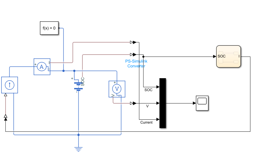
I am designing a battery model and its control to undergo cyclic charge and discharge.
The battery model is created by using a simscape electrical battery block (Table-based).
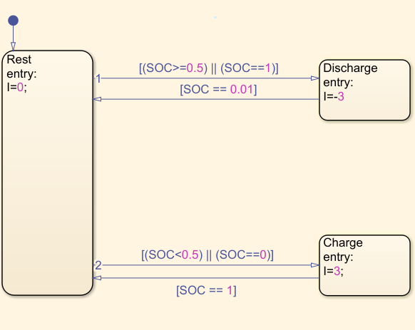
The control is modeled using Stateflow. The statflow chart takes SOC values as inputs and provide current values as outputs. By default, the battery will be at rest and no current is drawn at that state (I=0A). And then based on the SOC % of the battery, it goes to charge (3A current) or discharge (-3A current) state. I have defined the controls as follows.
- If the battery has SOC >= 50%, it has to discharge. If the battery has SOC < 50%, it has to charge.
- While discharging, if the battery reaches 0% SOC, it goes to rest.
- While charging, if the battery reaches 100% SOC, it goes to rest.
I have defined initial SOC as 50%.
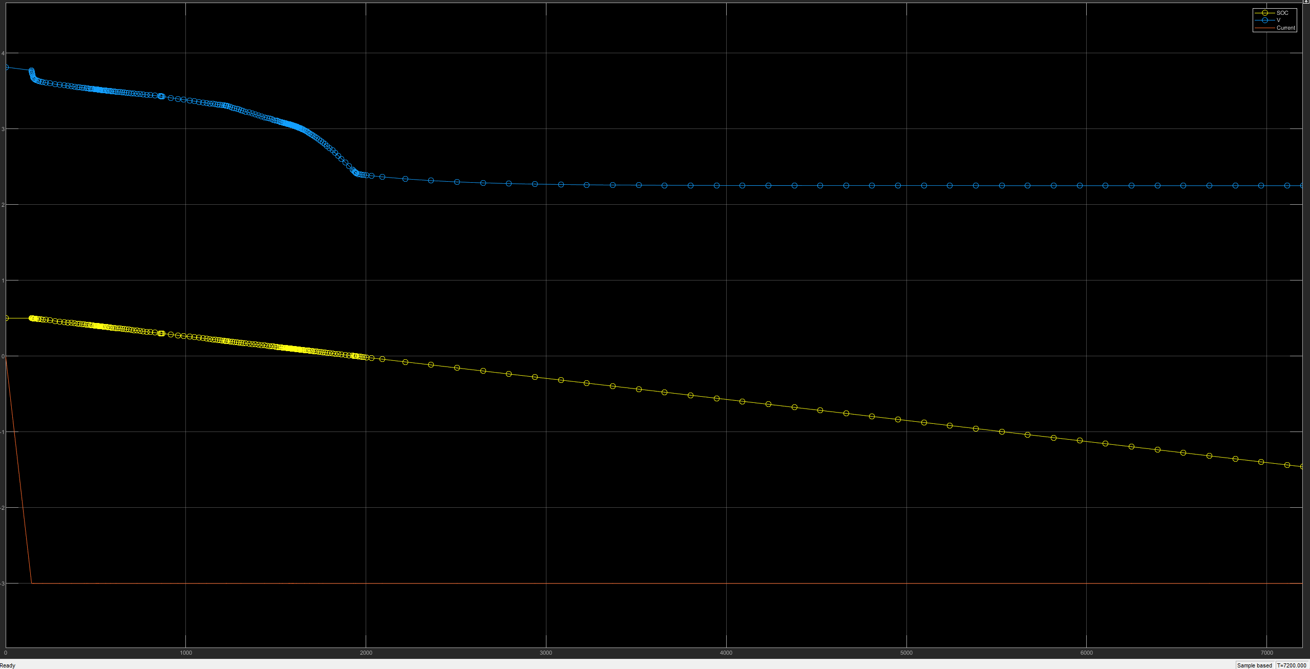
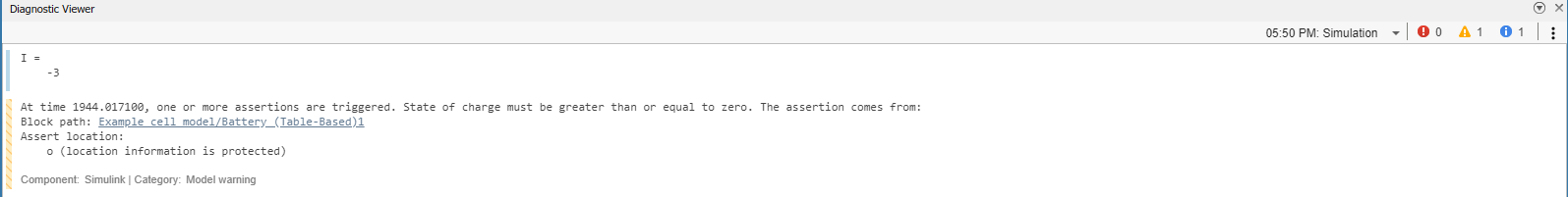
When I run the simulation, the battery started to discharge as per the condition provided in the stateflow chart.
I = -3
But the battery has not come to rest state after reaching 0% S0C.
I am getting a warning that,
At time 1944.017100, one or more assertions are triggered. State of charge must be greater than or equal to zero. The assertion comes from: Block path: Example_cell_model/Battery (Table-Based)1Assert location: o (location information is protected)
I don't understand why the battery has not came back to rest state.
Do anyone has any idea for the cause of this problem and how to resolve it?
Thanks in advance.
I need to model temperature rise of a resistor due to joule heating with a variable supply or a variable resistor. Is there a simulink component that can be used for this or it has to be implemented with the physical equations fed into block diagrams?
Can someone help give an idea of how this can be modeled?
I'm trying to simulate EV drive system using FEM PMSM and IGBT block of simscape electrical.
The simulation results (magnitude of the current in time domain) is quite similar with the experimental results.
But in frequency domain analysis using FFT (fast fourier transform), amplitude of current harmonics(specially 5, 7 th of fundamental frequency) are way to different.
Is there any way that I could increase my simulation accuracy?
I am trying to simulate a single phase H-bridge inverter connected to a load in Simulink using Simscape Electrical (blue wire). The simulation does not work. I tested the same circuit (with black wire). And everything works fine. I looked hard, I can't see any reason. Does anyone know why or have any examples?
You can find the simulation files in the attachment.
My goal with this is to start with a basic inverter scheme before testing multilevel converters. I had started with that but I had problems from the beginning...
Thanks in advance
hello can some body help me regarding designing a project in simulink to estimate the state of health of a battery ?... including kalman filter .... at least i need the battery cell equivalent circuit in simulink and the idea of the estimation method
many thanks
O.k., admit it. Who has done this (or something that resulted in the same loss of info) before?
>> laster
??? Undefined function or variable 'laster'.
>> lasterr
ans =
Undefined function or variable 'laster'.
D'Oh! I need a ERRORBEFORELASTERR function.
What's one of your dumb MATLAB mistakes?
About General
Discuss a wide range of MATLAB topics and share your thoughts and opinions with other community members.
This is the channel to post to if your topic doesn't fit any other channel contexts.
This is the channel to post to if your topic doesn't fit any other channel contexts.
 All technical questions
Community Guidelines MATLAB FAQs