Mistake with PWM generation using Simulink
Dear power electronics control community,
Since I have not solved the problem and have not found an answer to why I receive such an output, I would be happy when you could help me out. The actual project is much more extensive but easy schematic of what I want to do is here:
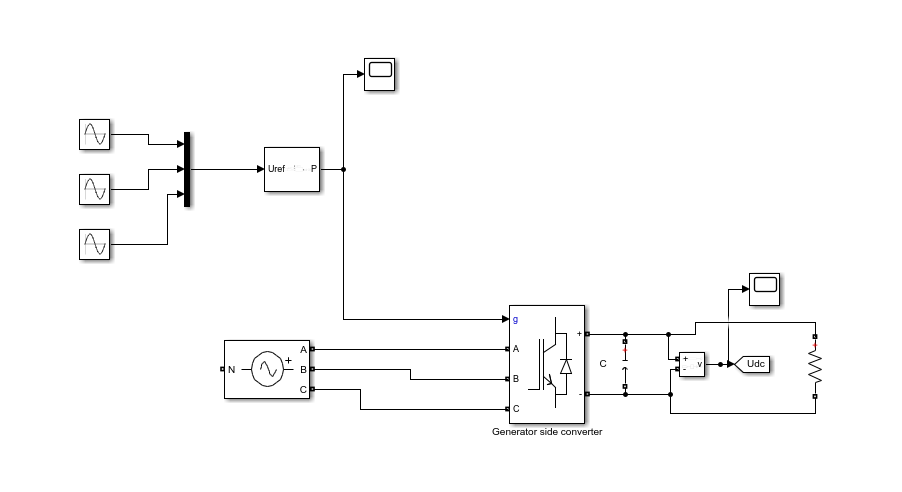
For that, I am using 2-level PWM generator: https://se.mathworks.com/help/physmod/sps/powersys/ref/pwmgenerator2level.html In the DC-link (DC voltage after the converter) the DC voltage output should be more-less constant (with a little noise) but right now it very far away from the desired output:
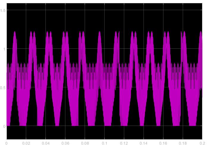
Does anyone have a idea what might cause this problem?
1 Comment
Time DescendingHello An,
as you are trying to use the block as an active rectifier, the main issue is making sure your PWM signals are properly aligned with the three phase voltage source. As you are running in open loop, there is the possibility these signals are not aligned properly to actually be rectifying the signal. This signal looks like something where that is the case. You should put a current sensor on your system. Anytime you have current flowing the other way, you know that your pulses aren't aligned. Also, you might need to invert your connection to keep your sign conventions the way you would want. (look at how using a standard inverter as a rectifier flips the signal).
Regards,
Joel