Stateflow
Model and simulate decision logic using state machines and flow charts
Have questions? Contact Sales.
Have questions? Contact Sales.
Stateflow is a product that provides a graphical language that includes state transition diagrams, flow charts, state transition tables, and truth tables. You can use Stateflow to describe how MATLAB algorithms and Simulink models react to input signals, events, and time-based conditions.
Stateflow enables you to design and develop supervisory control, task scheduling, fault management, communication protocols, user interfaces, and hybrid systems.
With Stateflow, you model combinatorial and sequential decision logic that can be simulated as a block within a Simulink model or executed as an object in MATLAB. Graphical animation enables you to analyze and debug your logic while it is executing. Edit-time and run-time checks ensure design consistency and completeness before implementation.

Connect AI Agents to Stateflow
Bring domain-specific capabilities to your agentic AI workflow.
With Stateflow, you can design state machines using drag and drop elements and simple logic statements. Stateflow Onramp and training are available to help you get started.

You can use flow charts to represent state logic. The Pattern Wizard lets you automatically generate flow charts for common logic patterns.
Stateflow has State Transition Tables and Truth Tables. State Transition Tables offer a tabular view for modeling logic, and Truth Tables implement combinatorial logic design in a tabular format.
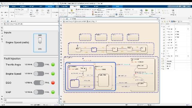
When executing your state diagram, animations highlight active states and transitions. You can manually modify variables during execution to visualize their impact on the system.

Simulation Data Inspector provides the ability to visualize simulation data. With this tool, you can monitor a system to gather valuable insights on its behavior.
Stateflow debugging capabilities let you step through chart execution in detail. You can set breakpoints and step through different functions in your state diagrams to understand unexpected behavior.

Stateflow can invoke Simulink algorithms in a periodic or continuous manner to schedule the execution of components and simulate your real-time environment.

Stateflow integrates seamlessly with other MathWorks products to verify, validate, and test your designs. You can leverage these products to ensure your designs satisfy requirements, find errors earlier, and meet quality objectives.

Code generation allows you to implement your state chart logic on embedded systems. Stateflow supports workflows to generate C, C++, VHDL, and Verilog code as well as Structured Text for PLCs.

“Until Deep Space 1, state charts and automatic code generation technology had not been used on large systems for spacecraft avionics software. MathWorks tools made this approach possible.”
You can design and develop supervisory control systems, fault detection, isolation and recovery systems, and task scheduling and event management embedded systems.
Stateflow charts and tables can be used in Simulink as a block and exchange data through input and output ports. You can also embed Simulink subsystems as states and functions within Stateflow. Stateflow can also invoke components in Simulink, acting as a task scheduler for Simulink components. Stateflow uses MATLAB syntax to define state actions, transitions, and conditions. Stateflow can also invoke MATLAB Functions to perform complex calculations or reuse existing MATLAB code.
Stateflow provides graphical animation that highlights active states and transitions during execution, and you can set breakpoints to step through chart execution in detail. You can also manually modify variables during execution to visualize their impact on the system.
Stateflow supports code generation for C, C++, VHDL, Verilog, and Structured Text for PLCs, allowing you to implement your state chart logic on embedded systems.
State Transition Tables offer a tabular view for modeling logic and are an ideal solution for simple, process-oriented, sequential state machines.
Yes, Stateflow can invoke Simulink algorithms in a periodic or continuous manner to schedule the execution of components and simulate your real-time environment.
You can use the Symbols Pane UI to inspect data during simulation, and you can also use Simulation Data Inspector to visualize simulation data and monitor a system across runs to gather valuable insights on its behavior.
Get pricing information and explore related products.
Your school may already provide access to MATLAB, Simulink, and add-on products through a campus-wide license.