Model and Architecture Design
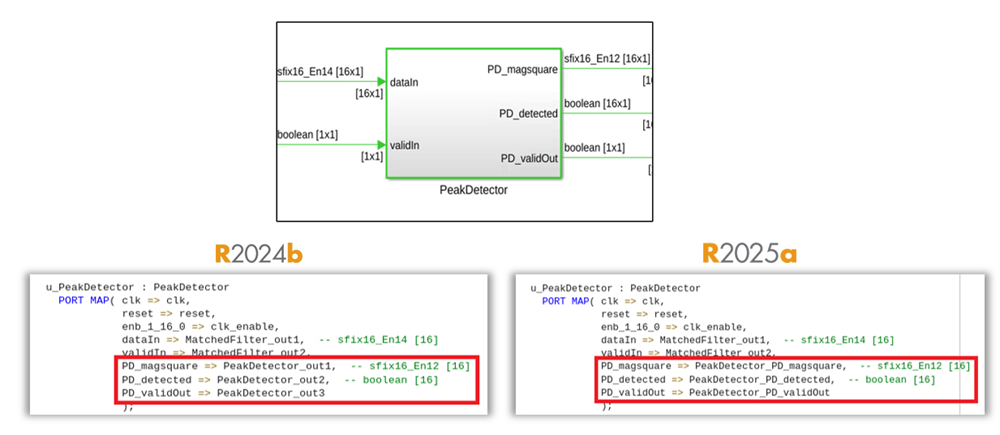
Output ports for subsystems in generated code now follow the naming format
<SubsystemName>_<PortName>. Previously, HDL Coder used
the format
<SubsystemName>_out<PortNumber>
for naming the output ports. This enhancement improves readability and provides more
descriptive names for the output ports in the generated HDL code.
HDL Coder uses this output port naming for these subsystems:
Subsystem
Model Reference
Subsystem Reference
Variant Subsystem
Triggered Subsystem
Resettable Subsystem
Enabled Subsystem
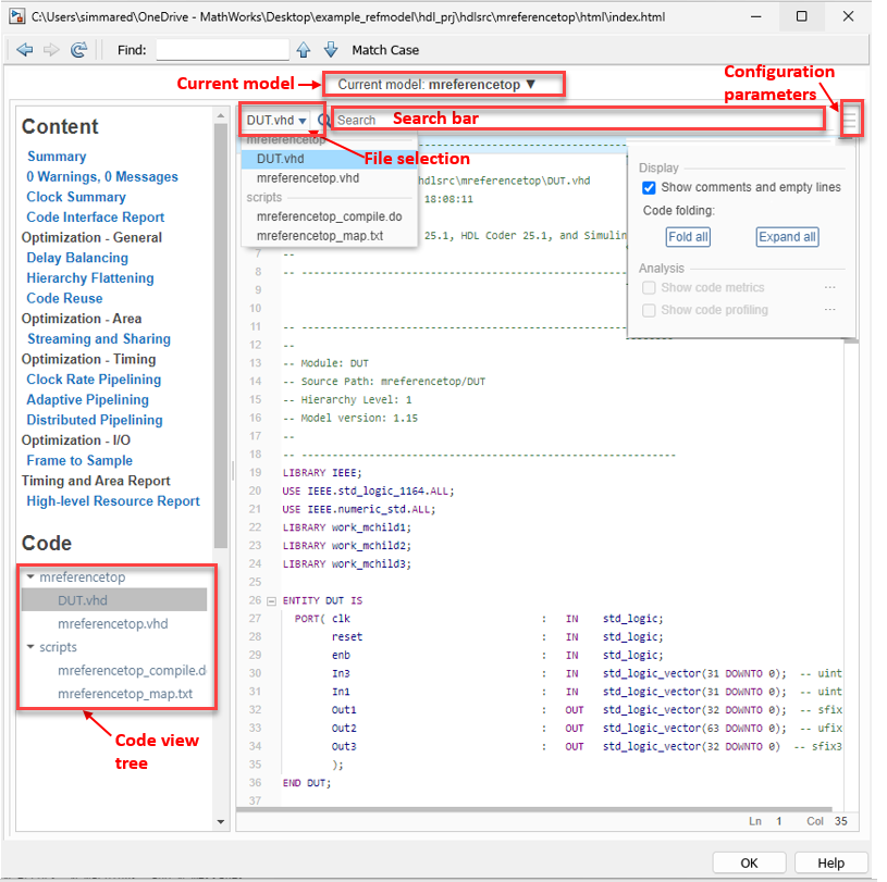
Starting in R2025a, the code generation report has improved formatting when you generate code for a top-level subsystem block. The report includes these improvements:
A new layout for generated code files that allows you to select files, including a file selector, a search bar, and a configuration parameters button
 that displays filters for the report.
The new configuration parameter pane, which you can use to:
Show comments and empty lines in the generated code.
Collapse or expand all sections in the generated code by using the Code folding option.
A new Current model file selector at the top of code generation report pane, which you can use to select the top-level subsystem. To select a referenced model, click the model name to view the model hierarchy and make your selection.
A new search bar at the top of the right pane, which you can use to find or highlight text in the code.
The code view tree panel in the left navigation pane, which lists the source code and script files generated for the top-level subsystem. When you select a source code file, the right pane displays the corresponding source code. Alternatively, use the new file selector at the top of the right pane to choose the file you want to view.
The left navigation pane, which you can adjust for better usability.
Block Enhancements
Code Generation and Verification
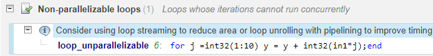
Use code insights during MATLAB-to-HDL code generation to facilitate better understanding and usage of the code. Code insights are messages about potential issues in the generated code, such as potential differences in behavior from MATLAB code or potential row-major issues. These messages appear in the Code Insights tab of the code generation report.
This image shows a code insight when you try and parallelize a non-parallelizable user-defined for-loop and there are no optimizations applied to the loop.
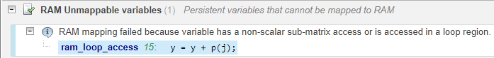
This image shows a code insight when you map to RAM and have a persistent variable access in a loop region.
Speed and Area Optimizations
When you use the streaming optimization for complex data type inputs, the optimized model uses
fewer resources than in previous releases. When you set the StreamingFactor HDL block property to a value greater than or equal to twice the input
size, HDL Coder applies the streaming optimization to complex inputs. Previously, HDL Coder allocated resources separately for the real and imaginary components which
results in the generated code consuming approximately twice the resources as the generated
code in R2025a. In R2025a, both real and imaginary parts share the same resource requiring
fewer resources.
For example, before R2025a if a model has a Gain block that operates on complex data, the generated model contains two Gain blocks. For example, this image compares a model that uses the streaming optimization in R2025a and R2024b. The Simulink model contains a Gain block that uses complex data. In R2024b, the generated model contains two multiplier blocks. In R2025a, the generated model contains one multiplier block, which results in reduced resource usage.
Additionally, HDL Coder now supports these streaming operations for complex data types:
Complex data type inputs to a real-value Gain block
Complex data type inputs to a real-value Sum block
Real-value inputs to a complex data type Gain block
Real-value inputs to a complex data type Sum block
Addition of complex data types
I/O Optimizations
High-Level Synthesis Code Generation
IP Core Generation and Hardware Deployment
When you perform HDL cosimulation using HDL Coder workflows, you now have the option to select the Synopsys® VCS® simulator to cosimulate the generated HDL.
You can use this feature with Simulink in these scenarios:
When using the
makehdltbfunction to generate a testbench, set theGenerateCosimModelproperty toVCS. For example:makehdltb("hdl_cosim_demo1/MAC",targetlang="vhdl",GenerateCosimModel="VCS")When using the Simulink HDL Workflow Advisor, open the configuration parameters for your model, and on the left pane, expand HDL Code Generation and select Test Bench. Then set Simulation tool to
Synopsys VCS.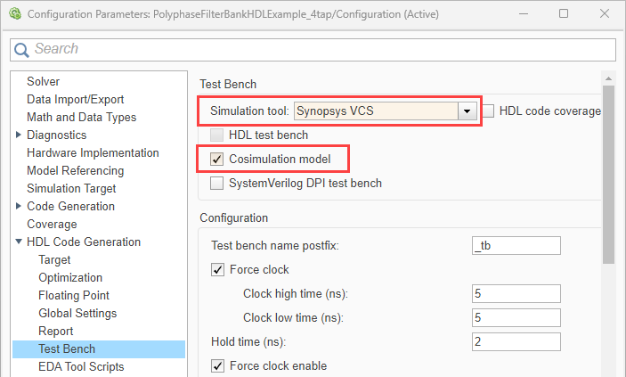
You can use this feature with MATLAB in this scenario:
When using the
coder.HdlConfigobject, set theCosimToolproperty toVCS. For example:hdlcfg = coder.config("hdl"); % Create a default "hdl" config hdlcfg.CosimTool = "VCS";
For more information, see Generate Cosimulation Model.
This feature requires an HDL Verifier™ license.
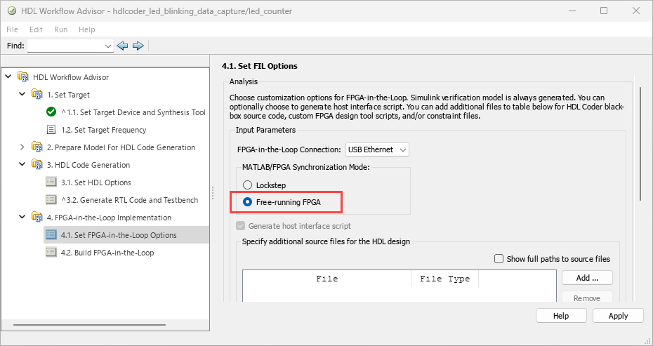
FPGA-in-the-loop in HDL Workflow Advisor supports free-running mode for streaming data between MATLAB and a DUT executing on an FPGA. This mode adds the option for the DUT to operate asynchronously with MATLAB.
To use this mode, in HDL Workflow Advisor, in the 4.1. Set FPGA-in-the-Loop Options step, under MATLAB/FPGA Synchronization mode, select Free-running FPGA.
The feature is supported on these SoC boards over an Ethernet or USB Ethernet interface:
ZedBoard™
AMD ZC702 Evaluation Kit
AMD ZC706 Evaluation Kit
AMD ZCU102 Evaluation Kit
AMD ZCU111 Evaluation Kit
AMD ZCU208 Evaluation Kit
AMD ZCU216 Evaluation Kit
AMD VCK190 Evaluation Kit
Intel Agilex® 7 SoC Development Kit (supported over Ethernet interface only)
Note
This feature works only when you use FIL with a MATLAB System object.
For more information, see Execute Free-Running FPGA-in-the-Loop Using HDL Workflow Advisor (HDL Verifier).
This feature requires an HDL Verifier license.
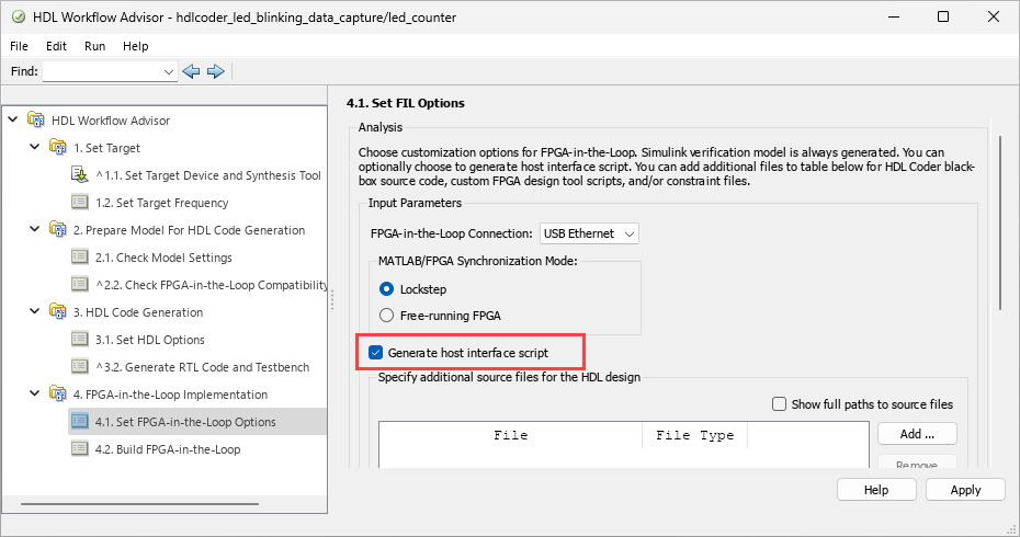
You can now generate a host interface script, gs_<DUTName>_interface_fil.m, when you use FPGA-in-the-loop in HDL Workflow Advisor.
This script creates a filObj object for interfacing with your FPGA from MATLAB. The interface script contains MATLAB commands that connect to your hardware and program the FPGA, and examples of how to exchange data with your algorithm as it runs on hardware.
To generate a host interface script, in HDL Workflow Advisor, in the 4.1. Set FPGA-in-the-Loop Options step, select Generate host interface script. For free-running mode, this option is selected by default.
This feature requires an HDL Verifier license.
FPGA data capture in HDL Workflow Advisor now supports the PS Ethernet and USB Ethernet interfaces. To run FPGA data capture over a PS Ethernet interface, in the 1.2. Set Target Reference Design step, set FPGA Data Capture (HDL Verifier required) to PS Ethernet. To run FPGA data capture over a USB Ethernet interface, set FPGA Data Capture (HDL Verifier required) to USB Ethernet.
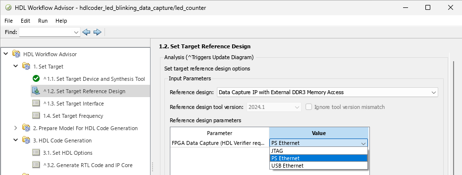
By default, the PS Ethernet and USB Ethernet options are available for these boards:
AMD ZCU102 Evaluation Kit (with the
Default system with data capture with external DDR4 memory accessreference design)AMD ZC706 Evaluation Kit (with the
Data Capture IP with External DDR3 Memory Accessreference design)ZedBoard (with the
Default systemreference design)
To enable these options for other boards, manually add the connection types in the
plugin_rd reference design definition file by using the addFPGADataCaptureInterface method before you start the HDL Workflow Advisor
tool.
You can enable PS Ethernet or USB Ethernet interface only when targeting these boards:
ZedBoard
AMD ZC702 Evaluation Kit
AMD ZC706 Evaluation Kit
AMD ZCU102 Evaluation Kit
AMD ZCU111 Evaluation Kit
AMD ZCU208 Evaluation Kit
AMD ZCU216 Evaluation Kit
For more detailed generation and data capture steps, see Data Capture Workflow (HDL Verifier).
This feature requires an HDL Verifier license.
FPGA data capture in HDL Workflow Advisor now supports external DDR memory to capture up to two gigasamples of large data. To expand the memory size for capturing the data, in the 3.2. Generate RTL Code and IP Core step, set FPGA Data Capture storage type to External memory and FPGA Data Capture buffer size to custom. Then, specify Custom Buffer Size as the required value, in powers of 2, 2N, where N is an integer from 7 to 31.
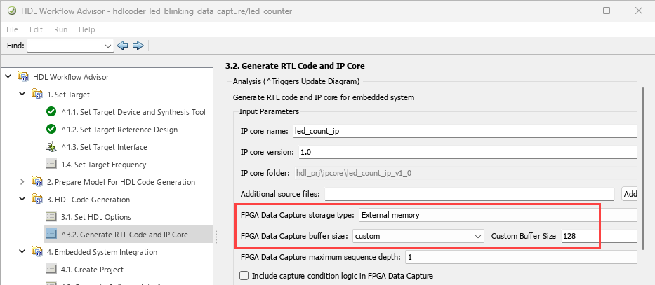
By default, the External memory option is available for these boards:
AMD ZCU102 Evaluation Kit (with the
Default system with data capture with external DDR4 memory accessreference design)AMD ZC706 Evaluation Kit (with the
Data Capture IP with External DDR3 Memory Accessreference design).
To enable this option for other boards, configure the plugin_rd
reference design definition file by using the addFPGADataCaptureInterface method before you start the HDL Workflow Advisor
tool.
Note
You can enable external memory only when targeting the AMD devices over a JTAG, PS Ethernet, or USB Ethernet interface.
For an example, see Debug IP Core Using FPGA Data Capture. For more detailed generation and data capture steps, see Data Capture Workflow (HDL Verifier).
This feature requires an HDL Verifier license.
Real-Time Hardware Deployment
Model and Architecture Design
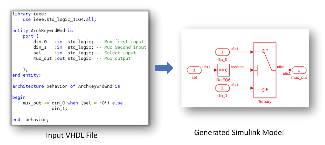
You can now import synthesizable VHDL code into the Simulink modeling environment. When you execute the importhdl (R2024b) function, the function analyzes the VHDL files and generates a corresponding Simulink model. This model visually interprets the VHDL code, showcases its functionality and behavior.
When you import the VHDL code, make sure that the constructs used in the HDL code are
supported by importhdl function. For more information, see Supported VHDL Constructs When Generating Simulink Models from VHDL Code (R2024b).
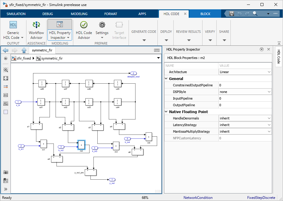
You can now edit the HDL block properties of a block or a subsystem by using HDL Property Inspector pane. When you use the HDL Property Inspector pane, you can set the HDL Properties as you work. The values take effect when you set them. For more information, see Set and View HDL Model and Block Parameters (R2024b).
To open the HDL Property Inspector pane from the Simulink Toolstrip, first open the HDL Coder app from the Apps menu. In the HDL Code tab, click HDL Property Inspector.
In the HDL Property Inspector, you can assign values to HDL block properties using the variables declared in MATLAB base workspace, mask workspace, or model workspace.
Block Enhancements
Code Generation and Verification
You can now generate a DPI testbench for the SystemVerilog target language by using
the Configurations Parameters dialog box and/or makehdltb
function.
To generate a DPI testbench for the SystemVerilog code, follow these instructions:
Open the configuration parameters for your model.
On the left pane, select HDL Code Generation. Set Language to
SystemVerilog.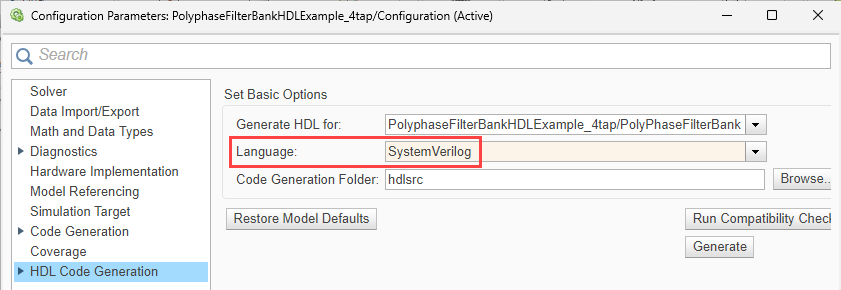
On the left pane, expand HDL Code Generation and select Test Bench. Select SystemVerilog DPI test bench.

Generate a DPI testbench by using the
makehdltb(R2024b) function. For example, use this command to generate the DPI testbench for thePolyphaseFilterBankHDLExample_4tap/PolyPhaseFilterBanksubsystem.makehdltb("PolyphaseFilterBankHDLExample_4tap/PolyPhaseFilterBank");
Alternatively, to perform steps 2 and 3, use the TargetLanguage (R2024b)
and GenerateSVDPITestBench (R2024b) arguments of the makehdltb
function, respectively. For example, use this command to set the target language to
SystemVerilog and generate the DPI testbench for the
PolyphaseFilterBankHDLExample_4tap/PolyPhaseFilterBank
subsystem.
makehdltb("PolyphaseFilterBankHDLExample_4tap/PolyPhaseFilterBank", ... "GenerateSVDPITestBench","Modelsim","TargetLanguage","SystemVerilog");
This feature requires an HDL Verifier license.
Speed and Area Optimizations
You can now apply HDL optimizations to Stateflow blocks to enhance your HDL code in terms of speed and area. You can use optimizations for Chart (R2024b) (Stateflow) blocks that model Mealy charts or Classic charts, State Transition Table (R2024b) (Stateflow) blocks, Truth Table (R2024b) (Stateflow) blocks and Requirement Table blocks.
You can leverage these HDL optimizations:
Clock-Rate Pipelining (R2024b)
Delay Balancing (R2024b)
Resource Sharing (R2024b)
Adaptive Pipelining (R2024b)
Distributed Pipelining (R2024b)
Critical Path Estimation (R2024b)
InputPipeline (R2024b)
OutputPipeline (R2024b)
ConstrainedOutputPipeline (R2024b)
Additionally, you can use these optimizations for Classic charts and Mealy charts:
Constant Multiplier Optimization (R2024b)
GuardIndexVariables (R2024b)
InstantiateFunctions (R2024b)
LoopOptimization (R2024b)
Map Persistent Variables To RAM (R2024b)
HDL Pipeline Pragma (R2024b)
You can also observe the associated latency of the block in the generated model, which is indicated by the number of delays. For more information, see Introduction to Stateflow HDL Code Generation (R2024b).

I/O Optimizations
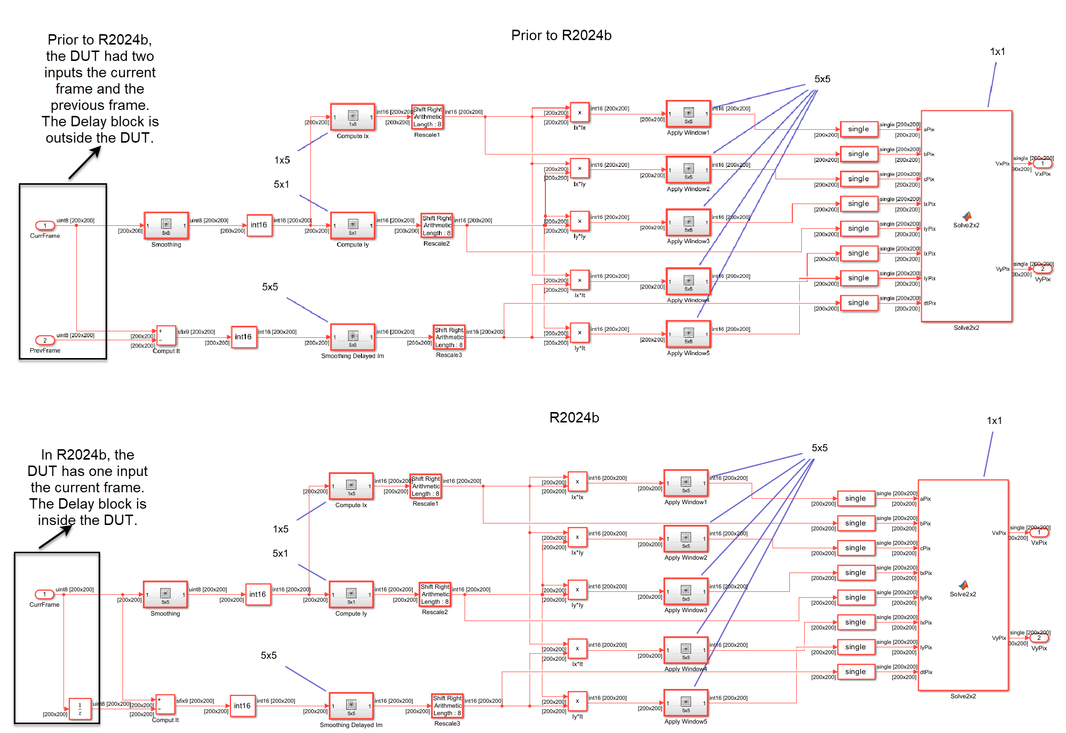
Reduce the complexity of your frame-to-sample algorithm models by using design delays inside the frame-to-sample algorithm. Starting in R2024b, you can:
Use Unit Delay and Integer Delay blocks inside the frame-to-sample design under test (DUT) subsystem. The delays can be of any length and must not be enabled or resettable.
Use persistent variables to create unit and variable integer design delays in MATLAB Function blocks inside the frame-to-sample DUT subsystem.
Use the Delay size threshold for external memory (bits) model configuration parameter to map design delays to external memory. The parameter can be found in the Configuration Parameters window, in the HDL Code Generation > Optimization pane, click the Frame to Sample Conversion tab.
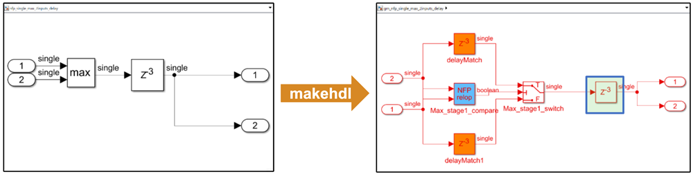
For example, this image shows the optical flow algorithm with the design delay outside the frame-to-sample DUT and the design delay inside the frame-to-sample DUT. Prior to R2024b, you modeled the current frame and the previous frame. In R2024b you model only the current frame and use a design delay inside the frame-to-sample DUT to represent the previous frame. The frame delays are mapped to external random access memory (RAM). See Generate HDL Code from Frame-Based Models by Using Neighborhood Modeling Methods (R2024b).
You can now perform neighborhood processing and element-wise or iterative operations on RGB images or 3-D matrices to generate synthesizable HDL code using the frame-to-sample conversion. You can use 3-D matrices as inputs for these neighborhood processing functions and blocks when you use the frame-to-sample conversion algorithm:
hdl.npufun (R2024b)
hdl.iteratorfun (R2024b)
Neighborhood Processing Subsystem (R2024b)
When you pass a 3-D matrix to the hdl.npufun function, the
function executes the kernel function on each sliding window in the input data. For each
plane of the 3-D matrix, the function carries out the sliding window operation based on
the defined kernel size. The function then maps the output of the kernel operation for
each plane to the corresponding pixels in that plane. See HDL Code Generation from Frame-Based Algorithms (R2024b).
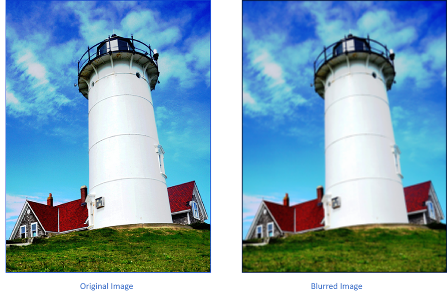
For example, perform the neighborhood processing algorithm to perform blurring operation on RGB image.
I_out = hdl.npufun(@blurringKernel, [5 5], I); function y = blurringKernel(N) out_R = sum(reshape(N(:,:,1)/25,[],1)); out_G = sum(reshape(N(:,:,2)/25,[],1)); out_B = sum(reshape(N(:,:,3)/25,[],1)); y = [out_R out_G out_B]; end
High-Level Synthesis Code Generation
IP Core Generation and Hardware Deployment
In R2024b, you can create designs and generate HDL code that utilizes the AMD floating-point library IPs. When you set the Synthesis Tool (R2024b) model
configuration parameter to Xilinx Vivado, you can set the
Vendor Specific Floating Point Library (R2024b) configuration
parameter to AMDFloatingPointOperators, which enables the
generation of code that incorporates both AMD floating-point IP blocks and HDL Coder native floating-point IP blocks.
See Generate HDL Code Using HDL Coder Native Floating Point and AMD Floating Point Library IP (R2024b).
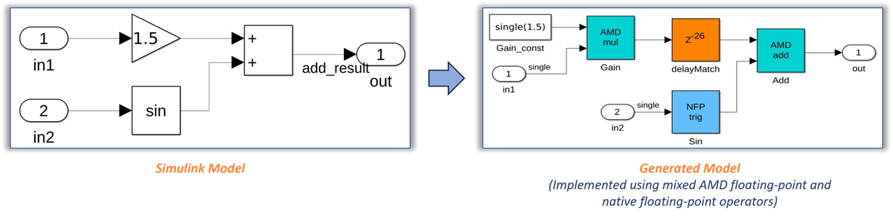
Because the AMD floating-point IP blocks are optimized for synthesis, you can map them to FPGA resources, including hardened DSP floating-point adder and multiplier (DSPFP32) primitives on Xilinx Versal devices. For other Xilinx device families, the generated HDL code uses the full DSP mode of the AMD floating-point operator. You can use this mixed-design approach to accommodate larger and more complex designs into the FPGA fabric. You can use this hybrid design with AMD floating-point libraries on Xilinx devices such as Versal, Zynq® UltraScale+™, and more. See hdlcoder.FloatingPointTargetConfig (R2024b).
In the HDL Workflow Advisor, you can generate the HDL code and IP core for your design with AMD floating-point IPs using the IP core generation workflow. You can also use the AMD floating-point library when you use the generic ASIC/FPGA workflow.
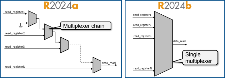
Prior to R2024b, mapping a large number of read registers to AXI4 or AXI4-Lite
interfaces when generating an IP core results in a long multiplexer chain that impacts
the maximum IP core frequency. Using the
AXI4SlavePortToPipelineRegisterRatio parameter to achieve the
target frequency, leads to a quadratic increase in resource usage due to the increase in
number of registers. In R2024b, HDL Coder replaces the long multiplexer chain with a single-case statement, which
improves the read address decoder critical path. See Optimize Timing on Register Interface (R2024b).
To control the structure of the read address decoder, use the Register interface read pipeline parameter in task 3.2 Generate RTL Code and IP Core of the HDL Workflow Advisor. Alternatively, use the Register interface read pipeline parameter in the Interface Settings tab of the IP Core Editor. During IP core generation, HDL Coder creates a multiplexer tree that distributes the specified pipeline registers. This image compares the address decoder architecture in R2024b and prior releases.
See The AXI4SlavePortToPipelineRegisterRatio HDL block property has been removed.
Starting in R2024b, HDL Coder saves the address assignments for each bus element to the bus-mapped
Inport and Outport blocks in the design under test
(DUT) to the IOInterfaceMapping HDL block property. Use the
IOInterfaceMapping property or the
hdlset_param function to view and edit the address for any of
the bus elements.
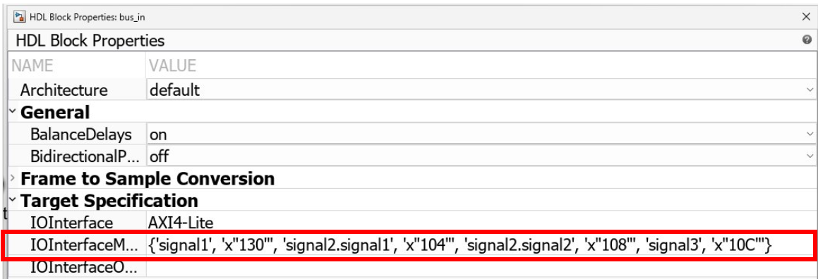
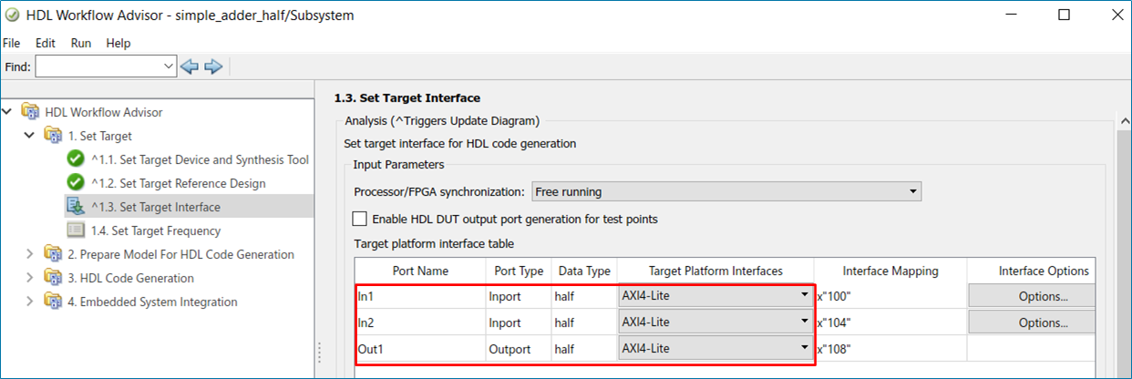
When you use the Target platform interface table in the Interface Mapping tab of the IP Core Editor or in task 1.3 Set Target Interface of the HDL Workflow Advisor, you still can view and edit only the address of the first bus element.
Simscape Hardware-in-the-Loop Workflow
You can now generate a Simulink state-space equivalent model for any desired Simscape network of your plant model while retaining the additional networks in their original forms. This enhancement helps to effectively use the resources on FPGA boards by enabling you to select only the network that you want to deploy on the hardware and not the entire model. This functionality enables optimization of HDL code for hybrid plant models (containing Simulink and Simscape blocks).
Previously, you could generate a state-space equivalent only for the entire model.
For example, consider sschdlexBoostConverterMultiNetModel model. In
this model, you can select the FPGA Subsystem block and generate a state-space
equivalent for it.
To generate a state-space equivalent for the FPGA Subsystem, open the Simscape HDL
Workflow Advisor for it by running the sschdladvisor (R2024b) function at the MATLAB command prompt.
sschdladvisor("sschdlexBoostConverterMultiNetModel/FPGA Subsystem")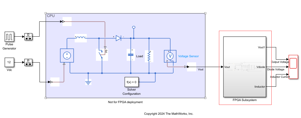
For more information, see Open Advisor for Subsystem (R2024b).
Model and Architecture Design
Block Enhancements
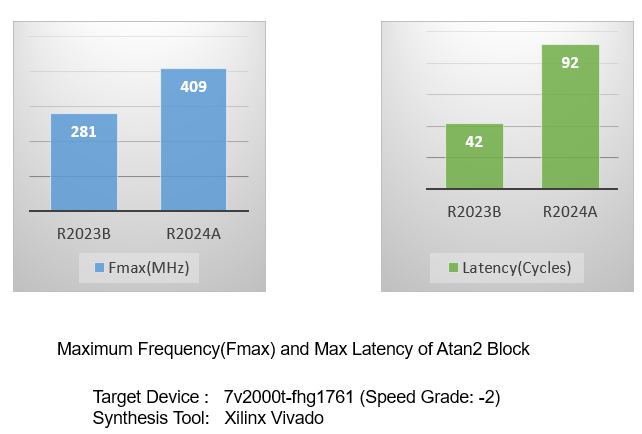
HDL Coder has enhanced the design implementation of the Atan2 block. The generated code for Atan2 blocks now has more pipelined stages and can be operated at higher frequency. This graph compares maximum frequency and maximum latency of an Atan2 block that has a single-precision floating-point input between R2024a and R2023b.
Code Generation and Verification
Speed and Area Optimizations
HDL Coder has made these improvements to delay balancing optimization:
Previously, HDL Coder generated a delay balancing error when delays were scattered in the design. For example, delay absorption was unsuccessful on this design:
In R2024a, delays can now be used to absorb latency regardless of their locations within a feedback loop. For example:
Previously, HDL Coder generated a delay balancing error when the code generator encountered fake loops in the design. A fake loop is a loop that appears in the design through hierarchy which when flattened is actually a feed-forward path. In this example, the two paths in the subsystem are actually data-dependent, and the loop is removed if we flatten away the subsystem.
In R2024a, HDL Coder no longer errors out due to latency introduced in a fake loop. For example:
Previously, you had to design single-rate models so that the latency was equal to a
stable serialization time or the streaming/sharing factor plus a stable computation
time. These settings led to a large oversampling factor, which resulted in reduced
throughput. Starting in R2024a, the minimum latency required for your single-rate models
is the number of cycles for which your input must be stable or the streaming/sharing
factor. For example, prior to R2024a, this model required an oversampling factor of 29.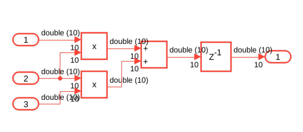
In R2024a, this model requires an oversampling factor of 10.
HDL Coder has made these improvements to resource sharing optimization:
Previously, HDL Coder moved and renamed the design delays anywhere in a subsystem level where sharing was requested with sharing candidates in a loop. For example:
In R2024a, resource sharing no longer moves and renames delays.
Resource sharing utilizes delays on feedback signals as latency budget for sharing in feedback loops more reliably. For more information, see Use Delay Absorption While Modeling with Latency (R2024a).
I/O Optimizations
High-Level Synthesis Code Generation
IP Core Generation and Hardware Deployment
You can now use the Cadence Genus synthesis tool in the HDL Workflow Advisor. You can generate HDL code and test benches for any MATLAB algorithm or HDL-compatible Simulink model, perform FPGA synthesis, and prototype on generic ASIC/FPGA platforms.
In the HDL Workflow Advisor task 1.1. Set Target Device and Synthesis
Tool, set Target workflow to
Generic ASIC/FPGA , Synthesis
tool to Cadence Genus, and
Tool version to 19.16.

Simscape Hardware-in-the-Loop Workflow
The Simscape hardware-in-the-loop (HIL) workflow now automatically determines the dynamic range of state-space matrices, and computes the appropriate fraction lengths and full precision integer rounding modes by using the specified word length. This reduces resource utilization and improves FPGA sampling frequency by reducing the oversampling factor.
To enable this feature through Simscape HDL Workflow Advisor, in the
Generate implementation model task pane, select
Fixed-point from the Data type
precision drop-down list. Once you select the
Fixed-point option, you can specify the word length in
the Fixed-point word length text box. This generates the HDL
implementation model in fixed-point data type with the specified word length. The
fixed-point data type is supported for Simscape models with single Simscape network that use the Backward Euler or Trapezoidal Rule local
solvers.

Model and Architecture Design
You can now insert custom comments in generated HDL code. You can print these comments in your generated code:
Model version
Model name
File name
You can use these macros to insert model version, model name, and file name comments in the generated code.
| Argument | Macro Syntax |
|---|---|
| Model Version | __MODELVERSION__ |
| Model Name | __MODELNAME__ |
| File Name | __FILENAME__ |
To enter these comments in your generated code, use Custom file header
comment or Custom file footer comment configuration
parameter settings in HDL Code Generation > Global settings >
Comments tab.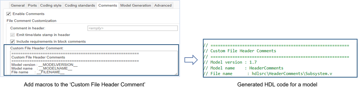
From R2023b, HDL Coder also prints the Simulink release version along with MATLAB, and HDL Coder release versions in default header comments. You can also print input and output port descriptions of a MATLAB Function (R2023b) block in the generated HDL code.
Block Enhancements
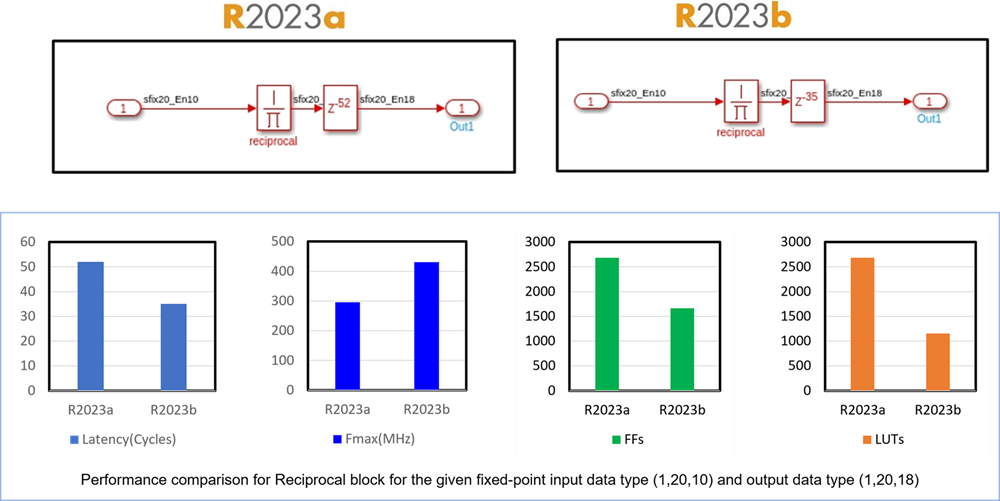
The Reciprocal, Math Function Reciprocal and HDLMathLib
Reciprocal blocks, now have reduced latency and uses fewer hardware resources when you
specify custom output data types.
For example, the latency of a Reciprocal block with an input data type of
fixdt(1,20,10) and an output data type as
fixdt(1,20,18) is 52 in R2023a and
34 in R2023b. This figure shows all the performance improvements
for this block.
Code Generation and Verification
Speed and Area Optimizations
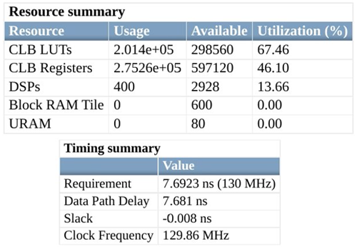
Starting in R2023b, when you enable streaming or resource sharing optimizations for your design and use clock-rate pipelining, the generated HDL code uses fewer lookup tables (LUTs) and registers in hardware. Additionally, when you enable distributed pipelining and streaming or resource sharing, there is a timing improvement for the generated HDL code on hardware. For example, before R2023b, for a model that has streaming, clock-rate pipelining, and distributed pipelining enabled, the synthesis resource summary for a Zynq UltraScale+ board shows that 67.46% of LUT resources and 46.10% of the registers on the board were used. The synthesis timing summary shows a maximum clock frequency of 129.86 MHz.
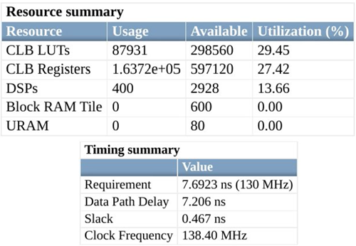
For the same model and target hardware in R2023b, the synthesis resource summary shows only 29.45% of the LUTs and 27.42% of the registers on board are used. The synthesis timing summary shows a higher maximum clock frequency of 138.40 MHz.
For more information on streaming, see Streaming (R2023b). For more information on resource sharing, see Resource Sharing (R2023b).
In R2023b, delay balancing results in minimal or optimal latency in the presence of buses. As a result, delay balancing can now work more reliably with buses in feedback loops. You can now generate HDL code without code generation errors for a model that has feedback loops inside the DUT containing bus signals or bus related blocks such as Bus Creator blocks.
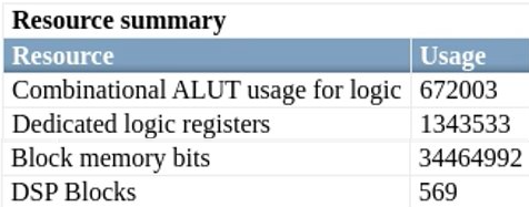
For example, before R2023b, for a model that has delay balancing enabled and buses in a feedback loop, where the feedback loop is outside of the DUT, the synthesis resource summary shows these resources on the target hardware were used.
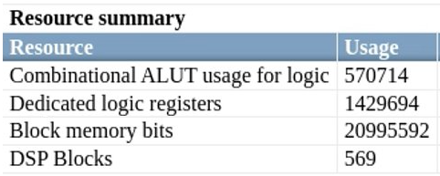
For the same model, but with the feedback loop inside the DUT, and same target hardware in R2023b, the synthesis resource summary shows a reduction in LUTs and an overall reduction in resources which hold state, such as block RAM and registers. This reduction comes from the ability to delay balance elements of buses instead of delay balancing the entire bus signal.
For more information on bus support for HDL code generation, see Signal and Data Type Support (R2023b). For more information on delay balancing, see Delay Balancing (R2023b).
I/O Optimizations
IP Core
                        Generation
and Hardware Deployment
Previously, to generate an IP core and custom reference design for your Simulink model, you could only use the HDL Workflow Advisor. When you make changes to the model or the settings in the HDL Workflow Advisor, you must re-run all subsequent steps in the advisor.
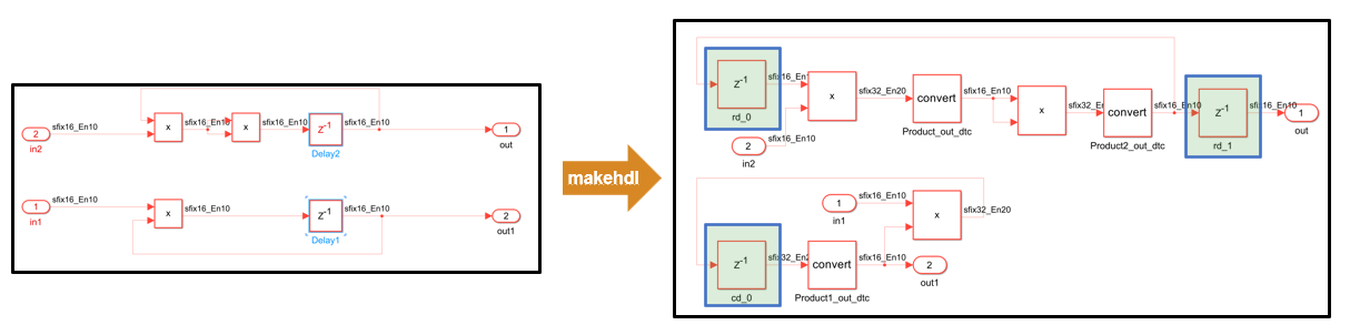
Starting in R2023b, you can configure the target interface for your hardware and generate an IP core using the Simulink Toolstrip, which makes it easier to perform design iterations and make frequent, incremental updates. You use the HDL Code tab in the Simulink Toolstrip to generate an IP core and use the IP Core Editor (R2023b) and the Configuration Parameters dialog box to configure the HDL and IP core settings. This diagram shows how you can rapidly prototype, generate an IP core, and iterate on your design using the Simulink Toolstrip.
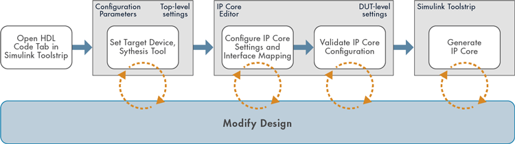
You can also use the HDL Code tab in the Simulink Toolstrip to generate, validate, and deploy an IP core with a reference design by using the Build Bitstream drop-down button. You can also generate a host interface script to verify your design on hardware by using the Host Interface Script button and generate a software interface model by using the Software Interface Model button. You can now generate a host interface script and software interface model without generating an IP core.


For more information on about how to perform HDL Workflow Advisor tasks using the Simulink Toolstrip, see Comparison of IP Core Generation Techniques (R2023b). For an example on how to use the Simulink Toolstrip to generate an IP core, see Getting Started with Targeting Xilinx Zynq Platform (R2023b).
Simscape Hardware-in-the-Loop Workflow
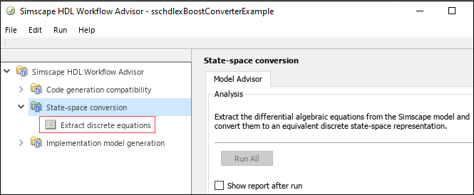
To get the state-space parameters from your model, the Simscape HDL Workflow Advisor now combines the extraction and discretization tasks into one new Extract discrete equations task. This enhancement streamlines the workflow by simplifying the conversion of your Simscape model to a state-space representation. It does not impact the HDL code generation results.
Previously, Extract equations and Discretize equations were two different tasks under State-space conversion.
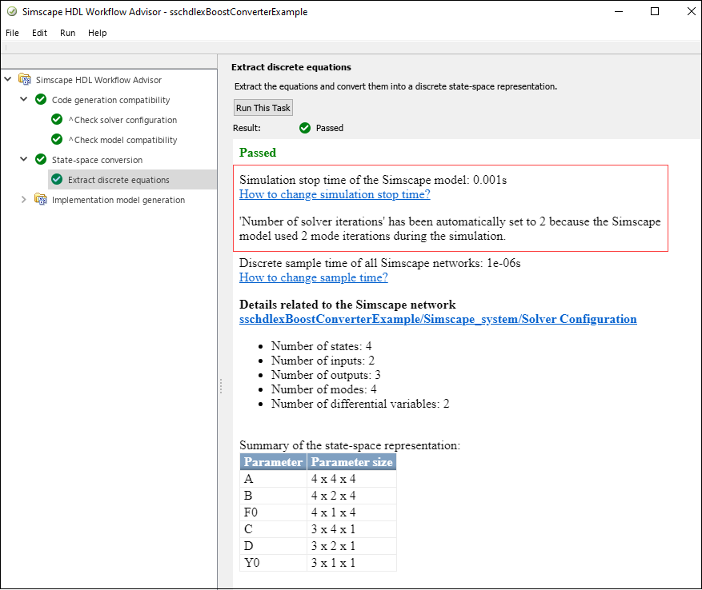
The Simscape HDL Workflow Advisor now displays an enhanced report for the Extract discrete equations task. Running this task produces a report summary. The summary now shows the Simulation stop time and Number of solver iterations in addition to details related to the Simscape network.
Previously, Simulation stop time was in the Extract equations task pane and Number of solver iterations was in the Generate implementation model task.
Model and Architecture Design
Block Enhancements
Starting in R2023a, resource sharing and streaming HDL optimizations now support
CORDIC operations, such as a Trigonometric Function block with the Approximation
method parameter set to CORDIC.
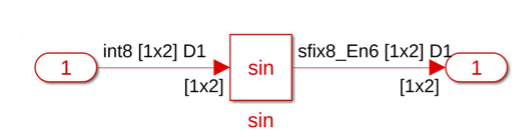
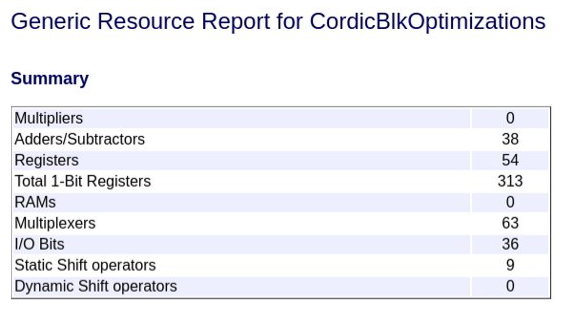
For example, suppose that you generate HDL code from the model in the image below,
which contains a subsystem that has a Trigonometric Function block with the
Function parameter set to sin and the
Approximation method parameter set to
CORDIC and no area optimizations applied. The resource report
shows the following area usage:
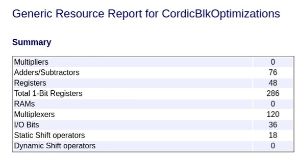
If you then set the subsystem StreamingFactor parameter to
2, the streaming applied to the Trigonometric Function
block reduces the Adders and Subtractors, Multiplexers, and Static Shift operators used by
the design by half.
For more information on resource sharing and streaming, see Resource Sharing (R2023a) and Streaming (R2023a).
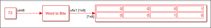
In R2023a, two new blocks, Bits to Word and Word to Bits, are available in the HDL Coder library. You can access these blocks from the Simulink Library Browser under HDL Coder > Logic and Bit Operations.
The Bits to Word (R2023a) block converts the N-sized input vector of one bit to the N-bit integer. The output of the block is an unsigned integer that has word length of N.
The Word to Bits (R2023a) block converts the integer of word length N to the output vector of one bit. The output of the block is a vector of size specified in the block parameter Maximum Word length.
The blocks have the following limitations:
You cannot use floating-point input for these blocks.
The Word to Bits block does not support vector, matrix, and bus inputs.
The Bits to Word block does not support matrix inputs.
Code Generation and Verification
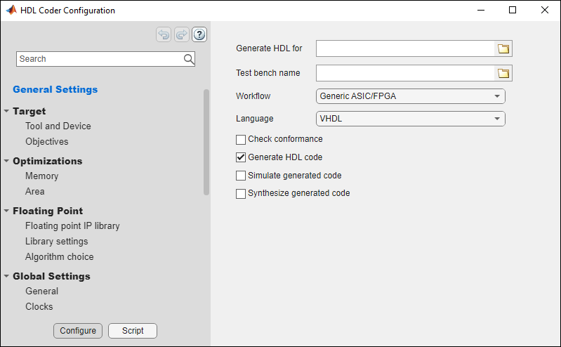
In R2023a, the configuration parameter dialog box for coder.HdlConfig (R2023a) and coder.FixPtConfig (R2023a) has a new layout. The
dialog box also has added functionalities, including search, informative tooltips, and an
option for generating equivalent MATLAB script.
You can open the configuration dialog box from the command line interface.
cfg = coder.config('hdl') % or cfg = coder.config('fixpt') open cfg
Alternatively, you can double-click the configuration object variable in the MATLAB workspace.
For more information, see Edit Configuration Parameters for HDL Coder (R2023a) and Edit Configuration Parameters for Fixed-Point Code Generation (R2023a).
Speed and Area Optimizations
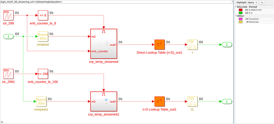
Previously, the generated model and HDL code of a design contained scheduling logic that had one scheduling counter per clock-rate pipelining region of the design, even if the design had multiple regions that required the same size counter, when generating HDL code with these conditions:
Clock-rate pipelining is enabled for the model
Streaming or resource sharing is enabled for the model
The model has an oversampling factor greater than or equal to the streaming or sharing factor
For example, this is a generated model that has two clock-rate pipelining
regions formed from two parallel paths that operate at the same rate in the original model
when streaming is enabled. Each enabled subsystem, crp_temp_streamed
and crp_temp_streamed1, acts as clock-rate pipelining regions and has
their own global scheduling counter that counts to 299 for the enable control of the
regions. For more information on scheduling logic, see Single-Rate Resource Sharing Architecture (R2023a).
Starting in R2023a, in order to avoid generating identical counters, HDL Coder generates only one global scheduling counter per model for all clock-rate pipelining regions that require the same size counter. For example, this image shows the new generated model. The model contains only one counter that goes up to 299, which the model uses as the enable control for both enabled subsystems.
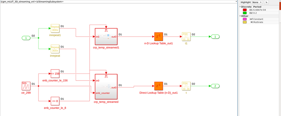
This change allows you to reduce area and resource usage previously needed to store multiple counters of the same size. Additionally, using a single counter instead of multiple counters can improve the reliability of the design on hardware because it removes the possibility that a glitch could occur in one counter that causes a misalignment with other counters of the same size.
I/O Optimizations
Frame-based algorithms often need to store large amounts of data during computations
for future processing by using delays needed for pipeline computations performed by the
hdl.iteratorfun and hdl.npufun functions. When
using the frame-to-sample conversion optimization, you can now map large integer delays to
input and output device under test (DUT) ports to offload the delays to external memory
outside of your FPGA and save resources on your FPGA that would otherwise be used to store
the delay. When you set the new model configuration parameter Delay size threshold
for external memory (R2023a) to a delay size threshold value in bits, delays
greater than this threshold are moved to external memory.
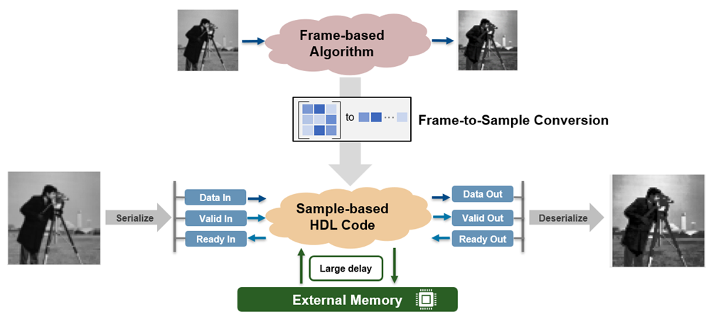
For information on deploying large delays to external memory for IP core generation, see the External memory access when generating an IP core from a frame-based algorithm release note.
IP Core Generation and Hardware Deployment
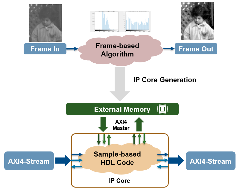
Frame-based algorithms often need to store large amounts of data during computations
for future processing by using delays for pipeline computations performed by the
hdl.iteratorfun and hdl.npufun functions.
Storing delays on an FPGA increases BRAM utilization and a typical FPGA does not have
enough resources to store large delays onboard. In R2023a, when you generate an IP core
and use the frame-to-sample conversion optimization and a delay is above the threshold set
by the Delay size threshold
for external memory (R2023a) parameter, this delay is mapped to external memory.
The external memory connects to your IP core through an AXI4 master interface and does not
require modeling the simplified AXI4 master protocol. For an example, see Offload Large Delays from Frame-Based Models to External Memory (R2023a).
For more information on enabling external memory for large delays, see the Map large delays to external ports when generating code from a frame-base algorithm release note.
In R2023a, you can map matrix ports to AXI4-Stream video interfaces by using the frame-to-sample conversion optimization. Use the frame-to-sample conversion optimization to:
Prototype programmable vision algorithms in Simulink by using frame-based modeling.
Test functionality on live video input and output.
Enable the IP core wrapper to insert a video porch and handle the start-of-frame (SOF) signal.

See Deploy Frame-Based Models with AXI4-Stream Video Interfaces in Zynq-Based Hardware (R2023a).
Simscape Hardware-in-the-Loop Workflow
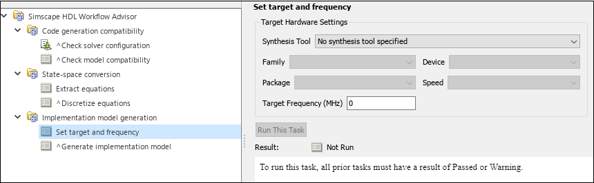
The Simscape hardware-in-the-loop workflow now provides an option to add target hardware information before the generation of the HDL implementation model. This option helps to incorporate the HDL optimizations required for the hardware deployment.
To use this option, open Simscape HDL Workflow Advisor for your model and run through
the steps until you reach the State-space conversion folder. Then,
under the Implementation model generation folder, click the
Set target and frequency task. This opens the Target
Hardware Settings in the right pane. You can specify the
Synthesis Tool, target FPGA part details, and the
Target Frequency (MHz) for generating the HDL implementation
model.
Once you specify the Target Hardware Settings in the Simscape HDL Workflow Advisor for generating an HDL implementation model, you can see the same information when you click on the HDL Code Generation > Target option in the Configuration Parameters dialog box of your generated model.
Similarly, these hardware specifications are set in the HDL Workflow Advisor window when you open it from the generated HDL implementation model.
For more information, see Simscape HDL Workflow Advisor Tasks (R2023a).
Model and Architecture Design
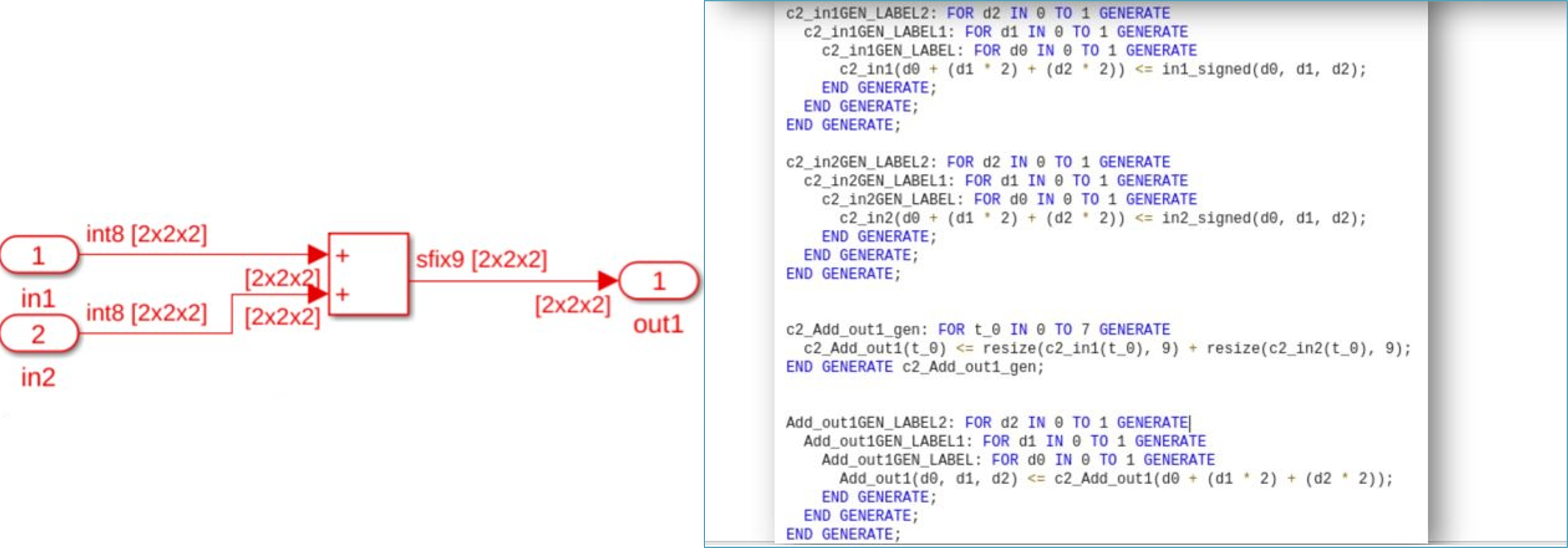
You can now generate HDL code for the Simulink blocks that support 3-D arrays with fixed-point and floating-point data types as input. You can use this functionality in a design under test (DUT) interface and model reference. You can also generate a test bench for a model that has 3-D arrays as inputs.
This figure shows an HDL code snippet for the Add block with an input of size [2-by-2-by-2].
These blocks support this functionality:
Simulink Blocks
| Add (R2022b) | Product (element-wise) (R2022b) | Selector (R2022b) | Reshape (R2022b) | Gain (R2022b) |
| Concatenate (R2022b) | Multiport Switch (R2022b) | Switch (R2022b) | Complex to Real-Imag (R2022b) | Real-Imag to Complex (R2022b) |
| Integer Delay (R2022b) | Unary Minus (R2022b) | Rate Transition (R2022b) | Relational Operator (R2022b) | Constant (R2022b) |
| Abs (R2022b) | Logical Operator (R2022b) | Data Type Conversion (R2022b) | Trigonometric Function (R2022b) | Math Function (R2022b) |
| Sqrt (R2022b) | Decrement Real World (R2022b) | Decrement Stored Integer (R2022b) | Decrement To Zero (R2022b) | Increment Real World (R2022b) |
| Increment Stored Integer (R2022b) | Bit Shift (R2022b) | Bit Slice (R2022b) | Bit Rotate (R2022b) | Bit Reduce (R2022b) |
| Bit Set (R2022b) | Extract Bits (R2022b) | Saturation Dynamic (R2022b) | Dead Zone Dynamic (R2022b) |
Block Enhancements
The rSqrt block is available in the HDL Math Library. To use this block in your model, open HDL math library by using this command.
open_system('HDLMathLib') Reciprocal Sqrt Architectures
| Architecture | Latency |
|---|---|
| RecipSqrtNewton | Number of Iterations + 2 |
| RecipSqrtNewtonSingleRate | (Number of Iterations x 4) + 5 |
This figure shows the simulation results for an rSqrt block with the RecipSqrtNewton architecture and three iterations. The output of the block changes at 5 s, which is equal to latency of the block.
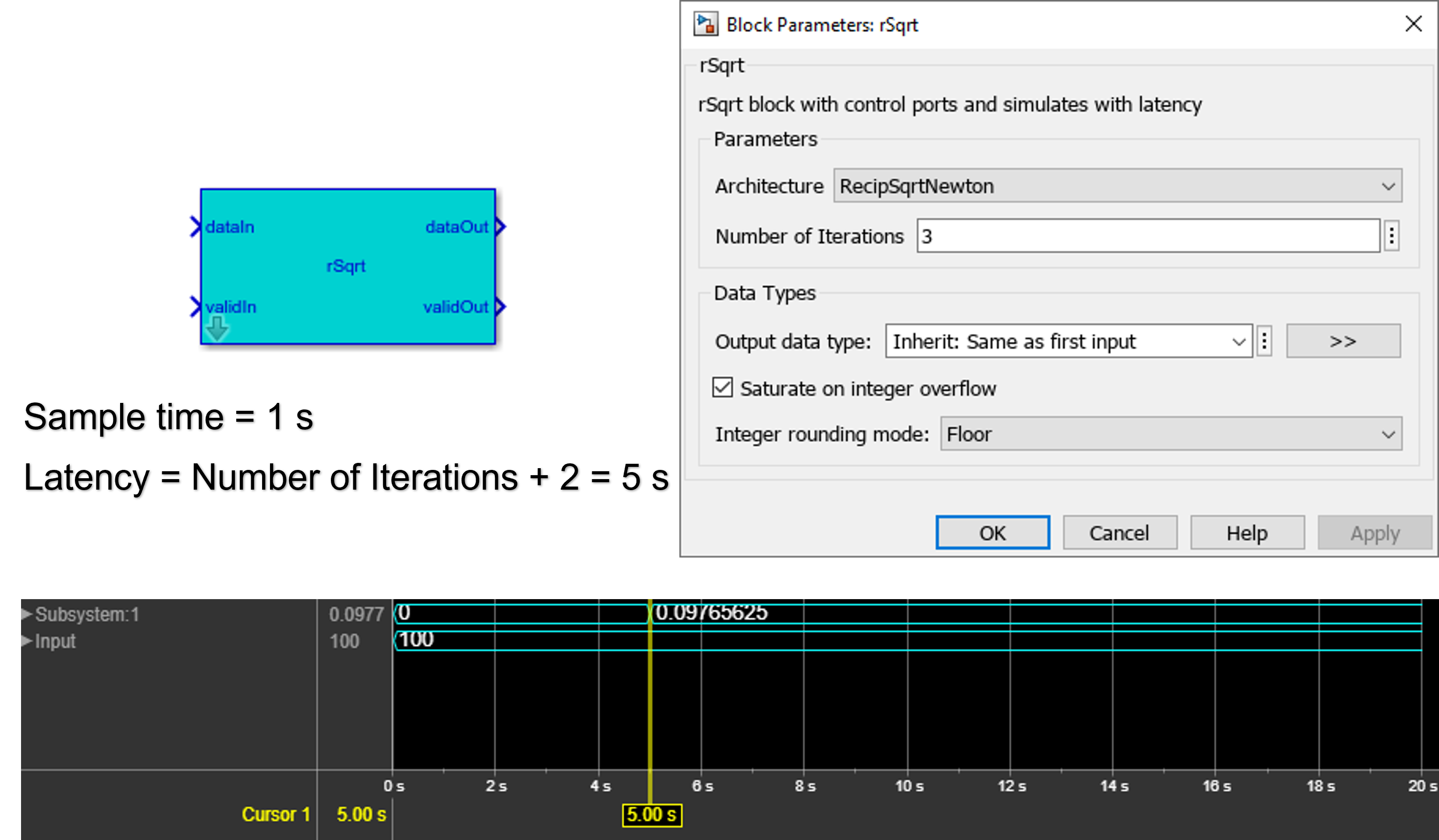
For more information, see Implement Control Signals-Based Mathematical Functions by Using HDL Coder (R2022b).
Code Generation and Verification
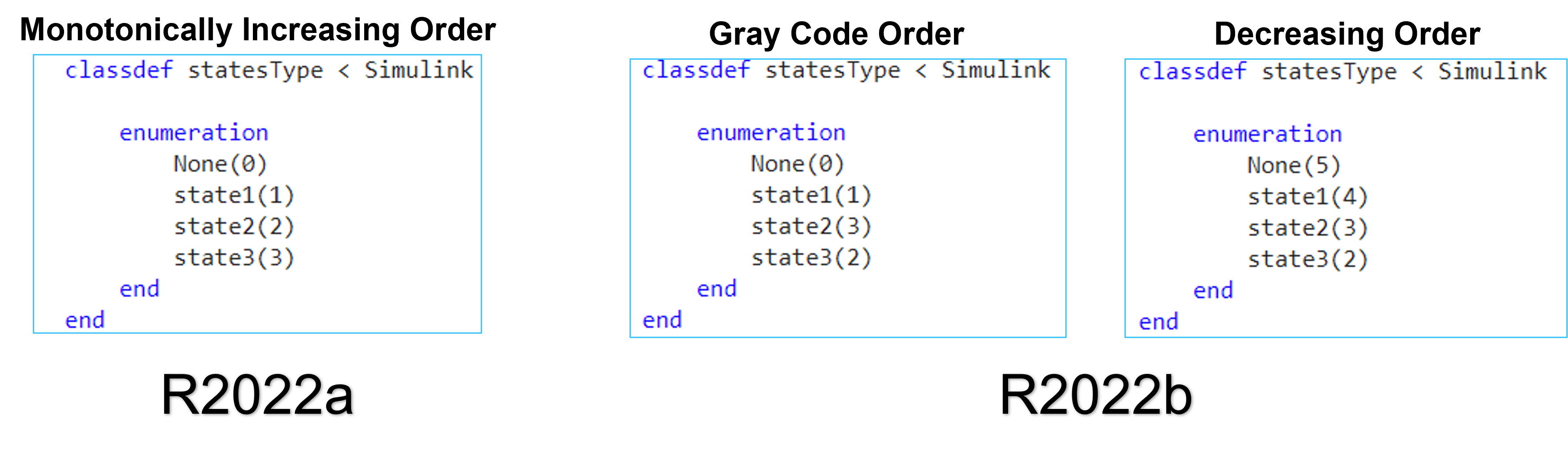
In prior releases, when you defined the enumerated types for states in Stateflow charts, you can generate HDL code only for enumerated types defined in monotonically increasing order. HDL Coder now supports any ordering of enumerated types in Stateflow charts. You can use this functionality for the Verilog target language in Mealy and Moore state machines.
Speed and Area Optimizations
There is now an enhanced delay absorption optimization that occurs during delay balancing of the model to absorb design delays more efficiently than in previous releases. Previously, delay absorption could only occur if a design delay was directly adjacent to an operator that required delays. In R2022b, delay absorption can absorb design delays separated by any component that does not take zero input and output a non-zero value, such as a NOT Logical Operator block. For example, before R2022b, this model produced this generated model and synthesis resource summary using the Xilinx Vivado synthesis tool:

In R2022b, the same model produces this generated model with the design delay absorbed into the delays needed for the NFP relop block and a synthesis resource summary that shows a reduction in registers used:
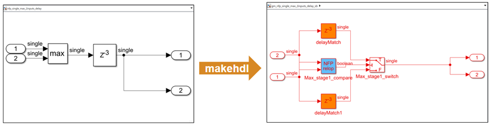

For more information on delay absorption, see Latency Considerations with Native Floating Point (R2022b).
In prior releases, you could generate the MCP constraints only between registers whose
clock enables are driven by the phase_0 clock enable signal. For
example, consider a multirate model that has Discrete FIR filter. When you select
enable-based constraints in the model, the timing controller logic generates three enable
phase registers: phase_0, phase_1, and
phase1_1. However, the MCP constraints are generated only for the
phase_0 register. Because you could not generate the MCP constraints
for all the phase registers, the FPGA synthesis tool could not provide accurate setup and
hold requirements for the combinational path. For more information on MCP constraints, see
Meet Timing Requirements Using Enable-Based Multicycle Path Constraints (R2022b).
You can now generate MCP constraints for all the phase registers, including registers that operate at different rates. This figure shows the generation of the MCP constraints are derived for all the phase registers in a multirate model.

You can use this functionality for the VHDL and Verilog target language. This support is available only for the Xilinx Vivado synthesis tool.
Use enable-based constraints to generate the MCP constraints for a multirate model. Synthesis tools, such as Xilinx Vivado, use MCP constraints to relax the setup and hold timing on multicycle paths in your design. HDL Coder generates a set of enable signals that drive the clock enables of the registers operating at different rates and different phases. The MCP constraints should be generated for all the different phases and rate. For an example, see Use Multicycle Path Constraints to Meet Timing for Slow Paths (R2022b).
IP Core Generation and Hardware Deployment
You can now access on-board memory locations in your FPGA design over an Ethernet connection for Xilinx boards by using the HDL Workflow Advisor tool. This feature provides faster performance than the AXI manager over a JTAG connection, which previous releases of the software support.
You can now automatically add the UDP AXI Manager IP into your FPGA design and connect
the added IP to the DUT IP by setting the Insert AXI Manager (HDL Verifier
required) parameter to Ethernet in the HDL
Workflow Advisor tool. The UDP AXI Manager IP connects to subordinate memory
locations on the board using the AXI4 or AXI4-Lite interface. The IP also responds to the
read and write commands from MATLAB or Simulink.
To automatically add and connect the UDP AXI Manager IP to your FPGA design, follow these steps in the HDL Workflow Advisor tool.
In 1.1. Set Target Device and Synthesis Tool, set Target workflow to
IP Core Generation.In 1.2. Set Target Reference Design, set Reference design to
Default Systemand Insert AXI Manager (HDL Verifier required) toEthernet. Set the IP address of your target board using Board IP Address.Note
By default, the
Ethernetoption is available for only the Artix®-7 35T Arty, Kintex-7 KC705, and Virtex-7 VC707 boards. To enable this option for other boards that have the Ethernet physical layer (PHY), manually add the Ethernet media access controller (MAC) Hub in theplugin_boardfile using theaddEthernetMACInterface(R2022b) method before you launch the HDL Workflow Advisor tool.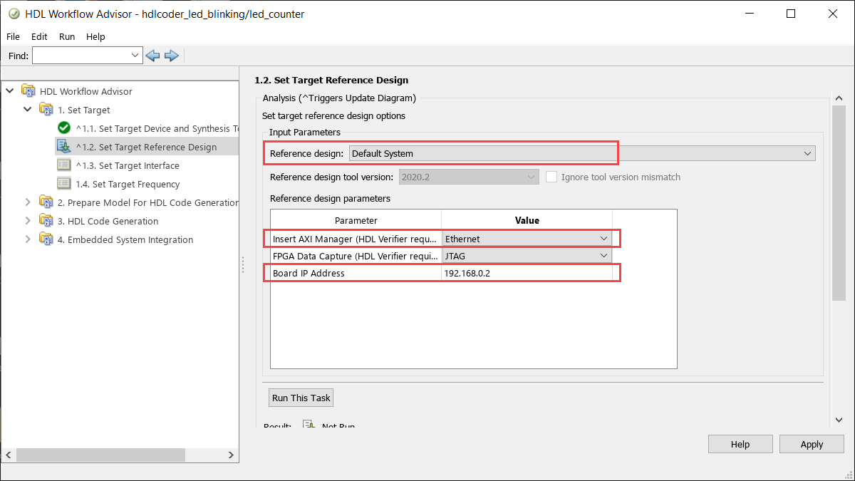
In 1.3. Set Target Interface, map each DUT signal that you want to access to the
AXI4orAXI4-Liteinterface.
To use this feature, you must install the HDL Verifier Support Package for Xilinx FPGA Boards. To access supported hardware for HDL Verifier software, see HDL Verifier Supported Hardware (R2022b) (HDL Verifier).
You can now capture a window of signal data from the FPGA and return the data to MATLAB or Simulink over an Ethernet connection for Xilinx boards by using the HDL Workflow Advisor tool. This feature provides faster performance than the FPGA data capture over a JTAG connection, which previous releases of the software support.
To automatically add and connect the data capture IP to your FPGA design for an Ethernet connection, follow these steps in the HDL Workflow Advisor tool.
In 1.1. Set Target Device and Synthesis Tool, set Target workflow to
IP Core Generation.In 1.2. Set Target Reference Design, set Reference design to
Default Systemand FPGA Data Capture (HDL Verifier required) toEthernet. Set the IP address of your target board using Board IP Address.Note
By default, the
Ethernetoption is available for only the Artix-7 35T Arty and Kintex-7 KC705 boards. To enable this option for other boards that have the Ethernet physical layer (PHY), manually add the Ethernet media access controller (MAC) Hub in theplugin_boardfile using theaddEthernetMACInterface(R2022b) method before you launch the HDL Workflow Advisor tool.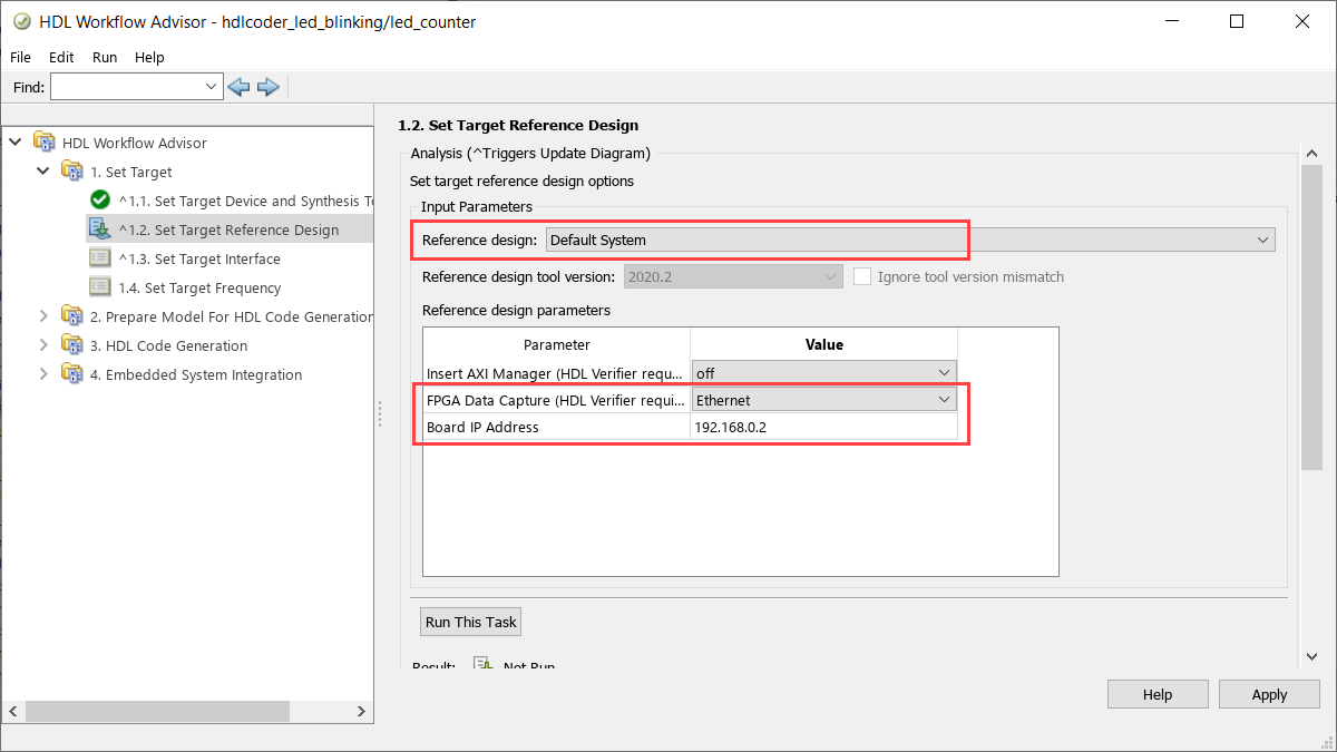
In 1.3. Set Target Interface, map each DUT signal that you want to capture to the
FPGA Data
                        Capture
interface.
For more information, see Data Capture Workflow (R2022b) (HDL Verifier Support Package for Xilinx FPGA Boards).
To use this feature, you must install the HDL Verifier Support Package for Xilinx FPGA Boards. To access supported hardware for HDL Verifier software, see HDL Verifier Supported Hardware (R2022b) (HDL Verifier).
FPGA data capture in the HDL Workflow Advisor now supports the capture condition logic. Include the capture condition logic in the HDL IP core to use a capture condition to control which data to capture from the FPGA. The HDL IP core evaluates the capture condition at each clock cycle and captures only the data that satisfies the capture condition. For more information on capture conditions, see Capture Conditions (R2022b) (HDL Verifier Support Package for Xilinx FPGA Boards).
To include the capture condition logic in the HDL IP core, select the Include capture condition logic in FPGA Data Capture parameter in the Generate RTL Code and IP Core task while generating the IP core using the HDL Workflow Advisor tool.
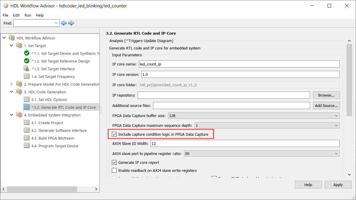
Then, set up a capture condition in the FPGA Data Capture
tool, the hdlverifier.FPGADataReader
System object, or the FPGA Data Reader block.
For more information, see Data Capture Workflow (R2022b) (HDL Verifier Support Package for Xilinx FPGA Boards).
To use this feature, you must install the HDL Verifier Support Package for Xilinx FPGA Boards or HDL Verifier Support Package for Intel FPGA Boards. To access supported hardware for HDL Verifier software, see HDL Verifier Supported Hardware (R2022b) (HDL Verifier).
Simscape Hardware-in-the-Loop Workflow
Model and Architecture Design
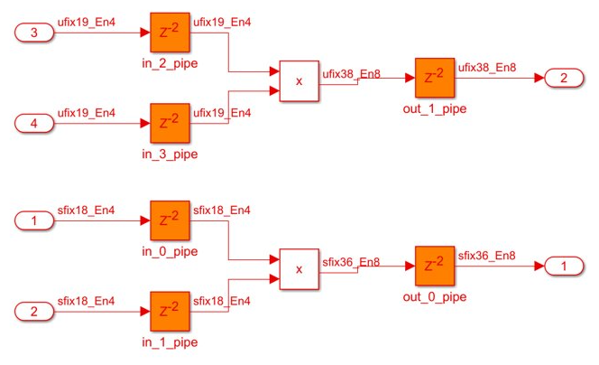
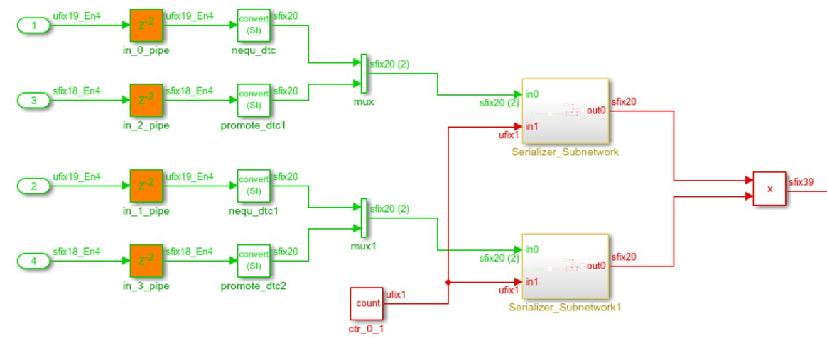
In R2022a, for models that have multiple deserializer outputs, HDL Coder generates one common counter that is shared between the serializer and deserializer. This counter reduces resource utilization and supports scalar, vector, and matrix inputs. During your hardware implementation, the counter might prevent these safety concerns:
Electrical surges might cause a value mismatch between multiple separate counters.
Reset timing of serializer and deserializers are different during an asynchronous reset potentially causing a phase difference between the separate serializer and deserializer counters.
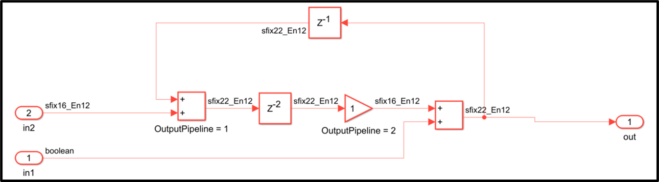
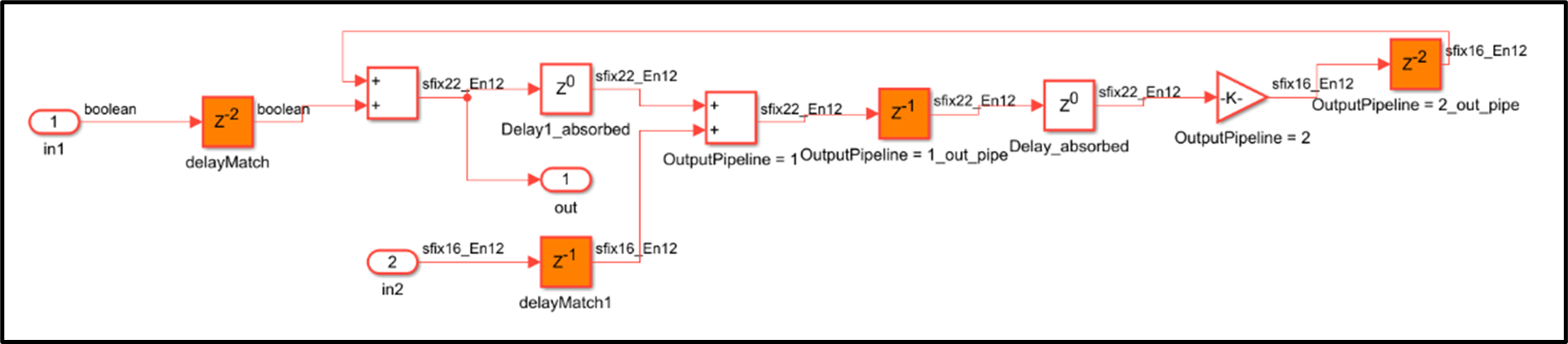
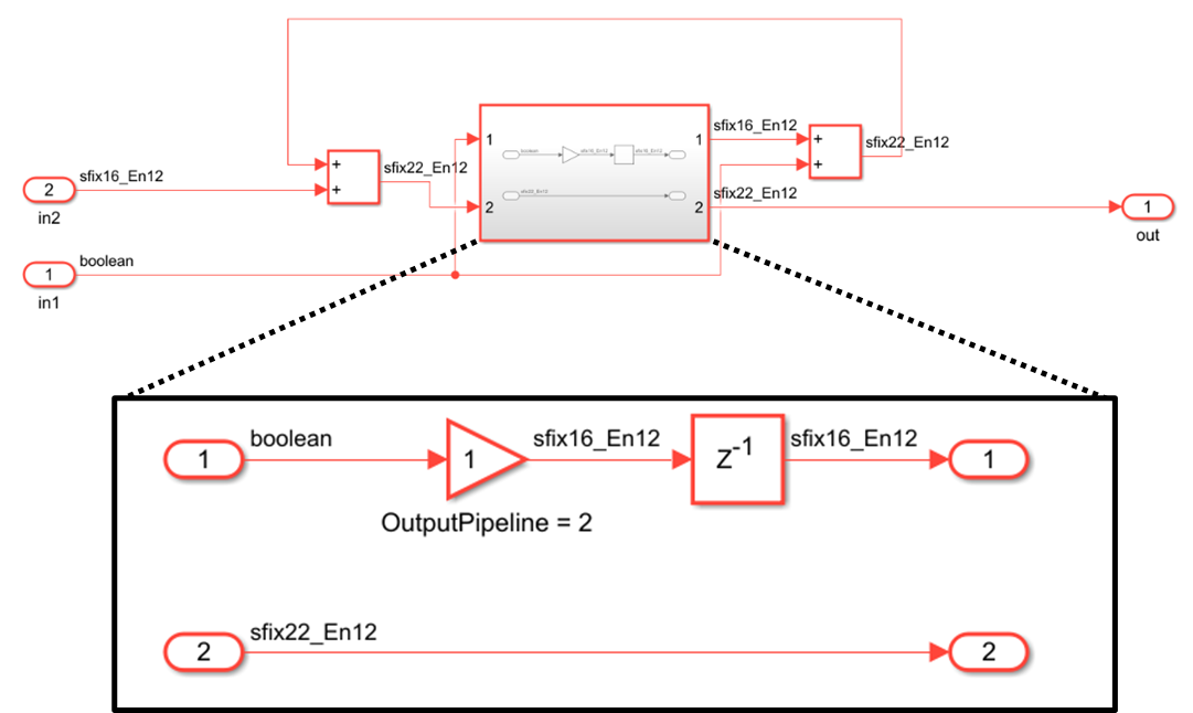
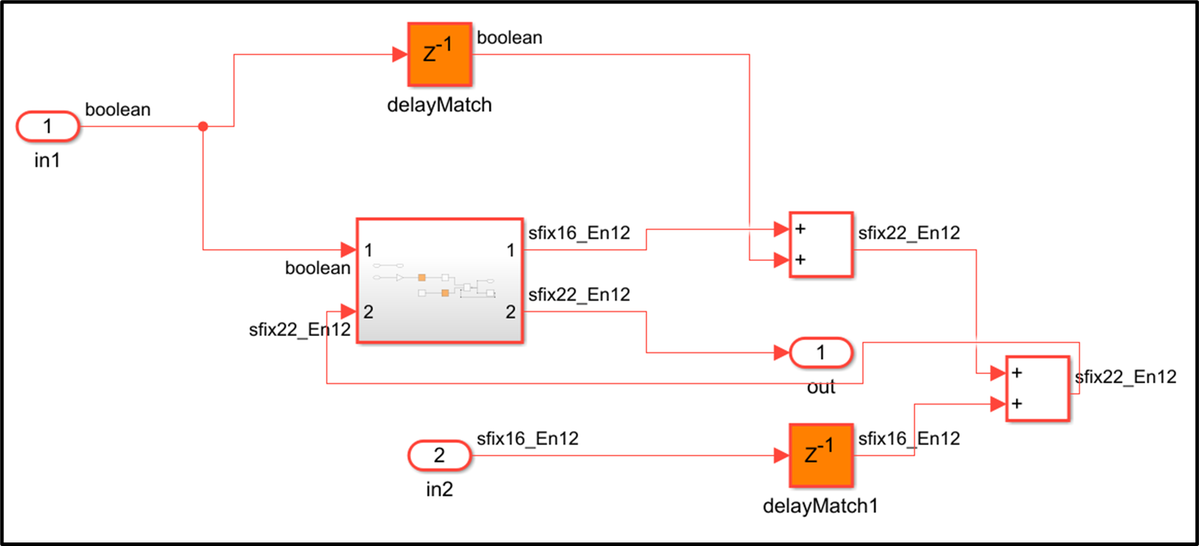
This image shows the comparison in the generated code before R2022a and in R2022a.
Generated model before R2022a
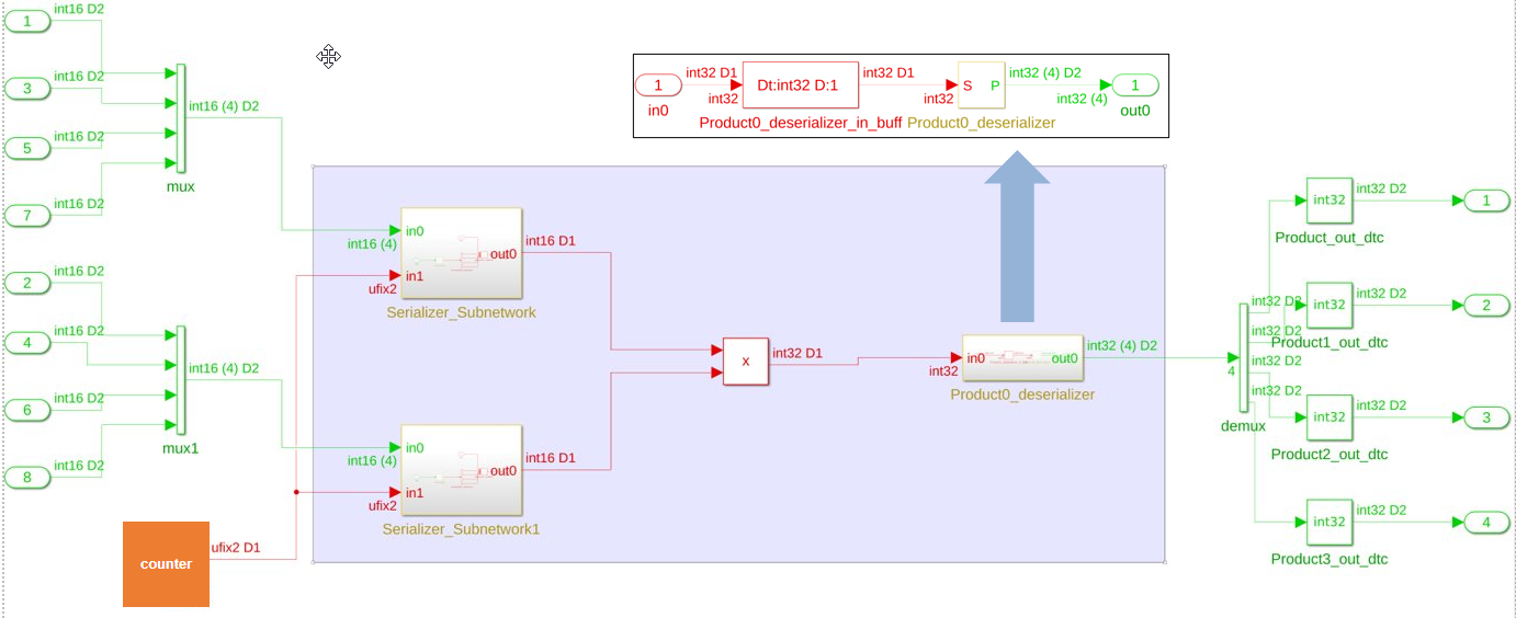
R2022a Generated model

In this image, the code inside the Deserializer_Subnetwork is shown
in detail in the box titled Deserializer_Subnetwork.
Inside Deserializer_Subnetwork, the enabled delay driven by the
same counter used for serializer output is produced by the multiplier when the counter
counts to a value equal to the sharing factor. In this example, the sharing factor is
four.
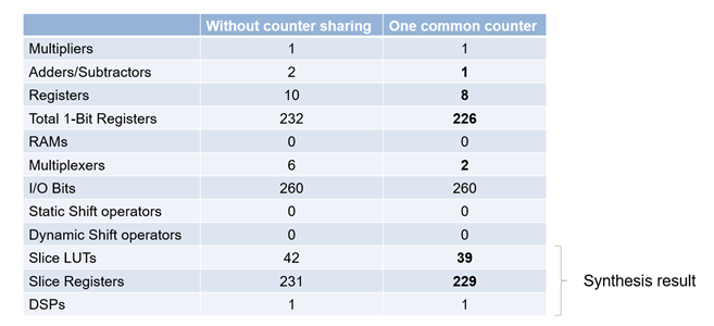
This image shows the resource utilization report comparison for the generated model without counter sharing and the generated model with counter sharing.
Block Enhancements
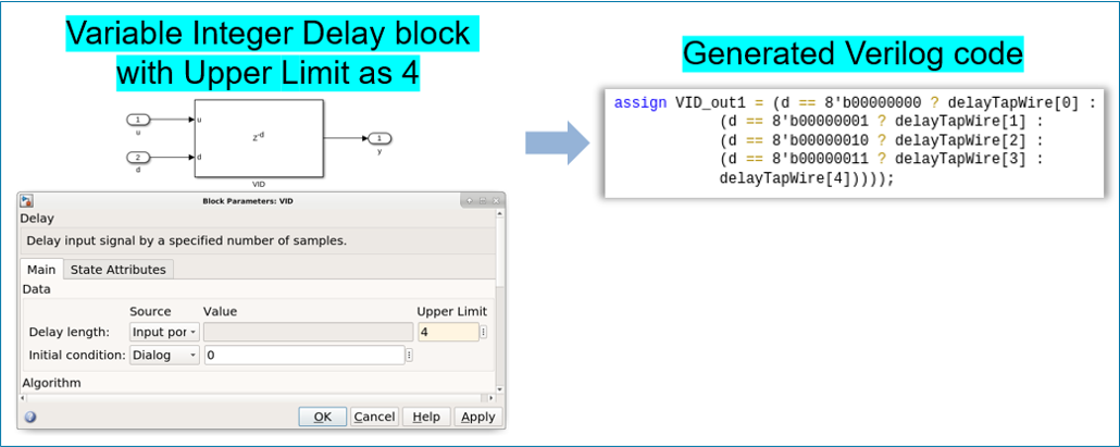
Starting in R2022a, you can generate HDL code for the Variable Integer Delay block.
You can now generate code for Delay (R2022a) block that has Delay length set through the
Input port. You can set the delay length by specifying the
constant value at the 'd' Input port of Delay block.
For a Simulink model consisting of multiple Delay blocks that have same delay length, you can specify the delay length of all the Delay blocks by using a constant instead of setting the delay length of each block. You can use enable and reset ports for the variable integer Delay block. For more details, see HDL Code Generation (R2022a).
In R2021b, HDL Coder added mapping large memory blocks, such as ultra from the
Xilinx family and M144k from the Quartus family on FPGAs. You can map FPGA memory blocks by specifying synthesis
attribute value in the HDL Block Property RAMDirective for Simulink
blocks. You can map FPGA memory blocks for Random Access Memory (RAM) blocks. For more
information, see RAMDirective (R2022a).
In R2022a, you can map FPGA memory blocks for HDL FIFO (R2022a) block. To specify these attributes in Simulink, configure appropriate attribute values for the RAMDirective in HDL Block properties of the HDL FIFO block.

To specify these attributes at the MATLAB command line, use the RAMDirective parameter name value
pair for hdl.RAM (R2022a) instantiation or use hdlset_param (R2022a) function. You can set the RAMDirective by
using either of these
commands:
hRam = hdl.RAM(‘RAMType’, ‘Dual port’, ‘RAMDirective’, ‘ultra’); or hdlset_param(<ram_block_name>, ‘RAMDirective’, <attribute_value>)
| Synthesis Tool | RAM Style Attribute | RAM Directive Values |
| Quartus | ramstyle | logic| M9K| M10K| M20K| M144K| MLAB |
| Xilinx | ram_style | block| distributed| register| ultra |
| Microsemi™ | syn_ramstyle | block_ram| registers| lsram| uram |
A new HDL Block Property AsyncRTAsWire is added for the Rate Transition (R2022a) block. For a Rate Transition block, when Output port
sample time has noninteger values, it is considered as asynchronous rates.
Enable the AsyncRTAsWire option to generate a wire when such
asynchronous rates are present for the Rate Transition block. This option is available
only when the Ensure data integrity during data transfer and
Ensure deterministic data transfer parameters are set to
off. 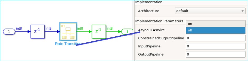
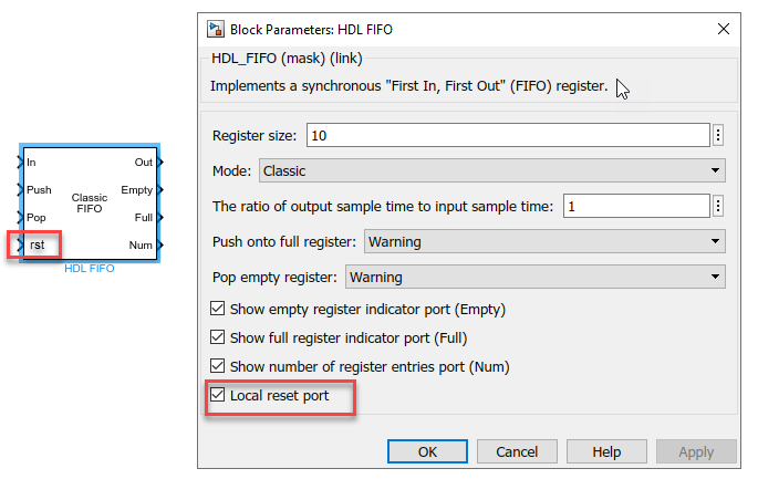
A new block parameter Local reset port has been added for HDL FIFO (R2022a) block. By enabling this option, you can insert an additional reset port for the HDL FIFO block. The generated HDL code for HDL FIFO block now has a reset port. When the reset port receives a value of 1, it resets the Empty, Full, and Num outputs of the HDL FIFO block.
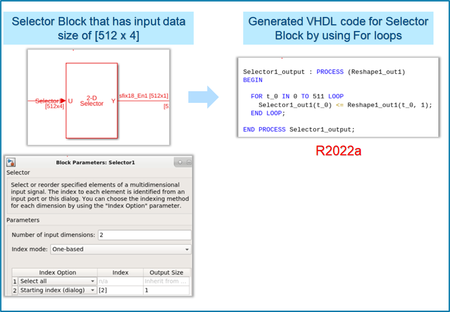
In R2022a, the coding style for Selector (R2022a) blocks has been improved. The generated HDL code for Selector block has these coding style enhancements:
The HDL code is generated by using
For loopswhen you select the target language asVHDL.By default, the loop unrolled code is generated when the target language is
Verilog.
For example, this image shows VHDL code generated for the Selector block by using
For loops. The generated HDL code has better code readability,
reduced lines of code, and reduced code generation time. For more details, see Unroll For-Generate Loops in VHDL code (R2022a).
The blocks in the HDL Math library perform the math and trigonometric operations.
These blocks have control ports, such as Valid_In and
Valid_out. For more information on HDL Math library blocks, see Implement Control Signals-Based Mathematical Functions by Using HDL
Coder (R2022a).
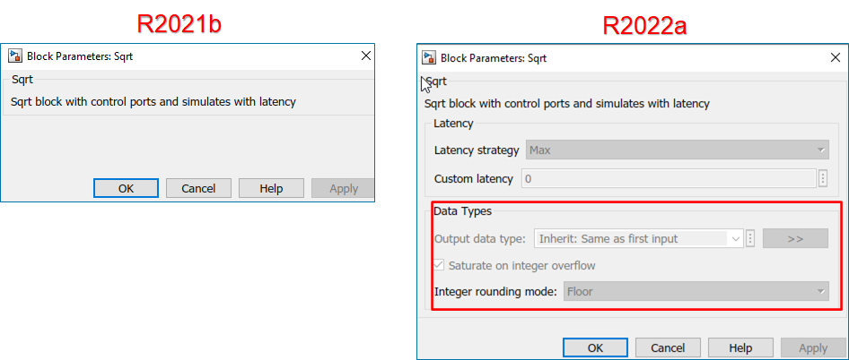
In R2022a, HDL Coder has provides these enhancements to the HDL Math library blocks:
The block parameters Latency strategy and Custom latency are added for the blocks in Block Parameter UI.
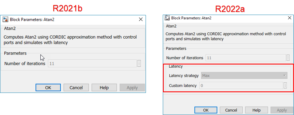
For Sqrt, Divide, and Reciprocal blocks in HDL Math library, the block parameters Output data types, Integer rounding mode, and Saturate on integer overflow are added to the Block Parameter UI.
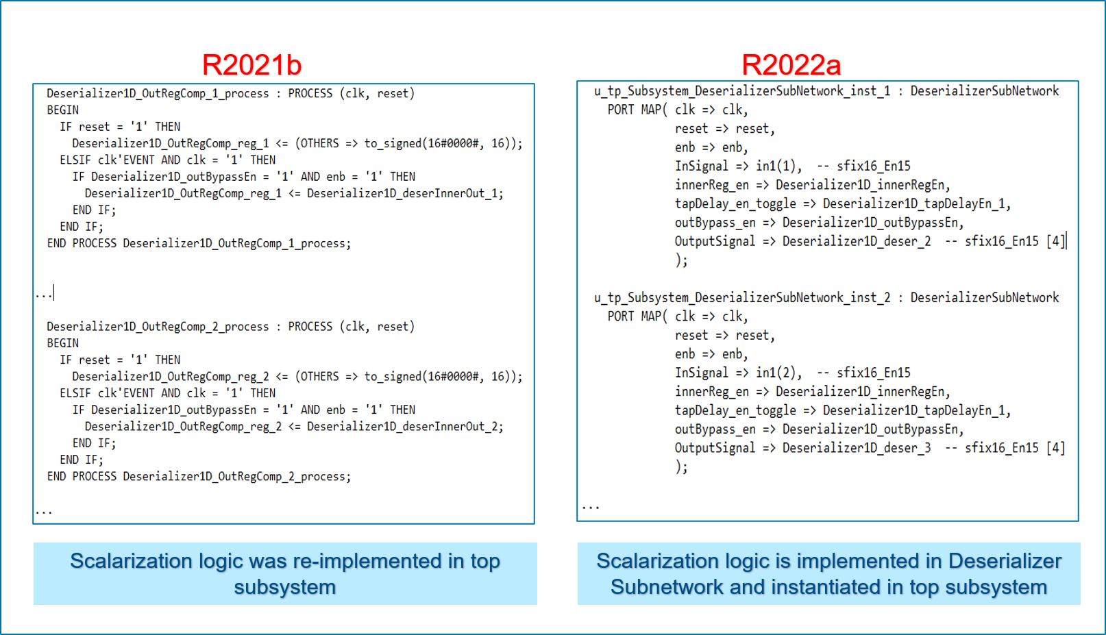
In R2022a, HDL Coder has enhanced code generation for the Serializer1D (R2022a) and Deserializer1D (R2022a) blocks. HDL code generation uses For-Generate
looping constructs for realizing Serializer1D and Deserializer1D blocks. You can now
generate code for Serializer1D and Deserializer1D blocks that have high-dimensions vector
inputs. For more details, see Unroll For-Generate Loops in VHDL code (R2022a).
For example, the figure shows the difference between generated HDL code for Deserializer1D block. In R2021b, the scalarization logic for Deserialzer1D block was re-implemented in a top-level subsystem based on the input vector size. In R2022a, scalarization logic is implemented in a Deserializer sub-network and it is instantiated in a top-level subsystem by using port mapping. The generated code has better code readability, reduced lines of code and reduced code generation time.
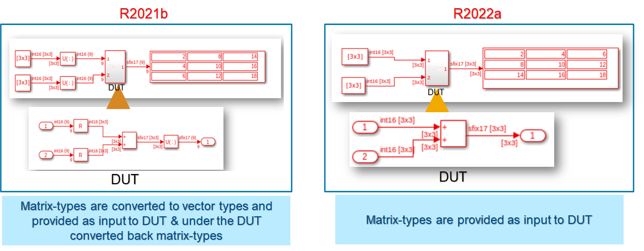
HDL Coder supports matrix types for various Simulink blocks. In R2021b, when you used these blocks in DUT subsystem, HDL code generation did not support matrix types at the DUT interface. To use matrix types inputs and outputs, you have to convert matrices to vectors at the DUT interface by using additional Reshape or Concatenate blocks.
Starting in R2022a, HDL Coder supports matrix types inputs and outputs at the DUT interface. This enhancement reduces the overhead of adding Reshape and Concatenate blocks inside the DUT and also improves readability of the generated HDL code.
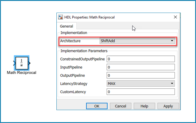
The reciprocal function in Math Function (R2022a) block now supports Shift-Add architecture. You can use the
HDL architecture as ShiftAdd in HDL
Block Properties for the reciprocal function in the Math Function block. Use Shift-Add
architecture to perform reciprocal operation on fixed-point data types by using a
nonrestoring division algorithm that performs multiple shift and add operations to compute
the reciprocal.
Code Generation and Verification
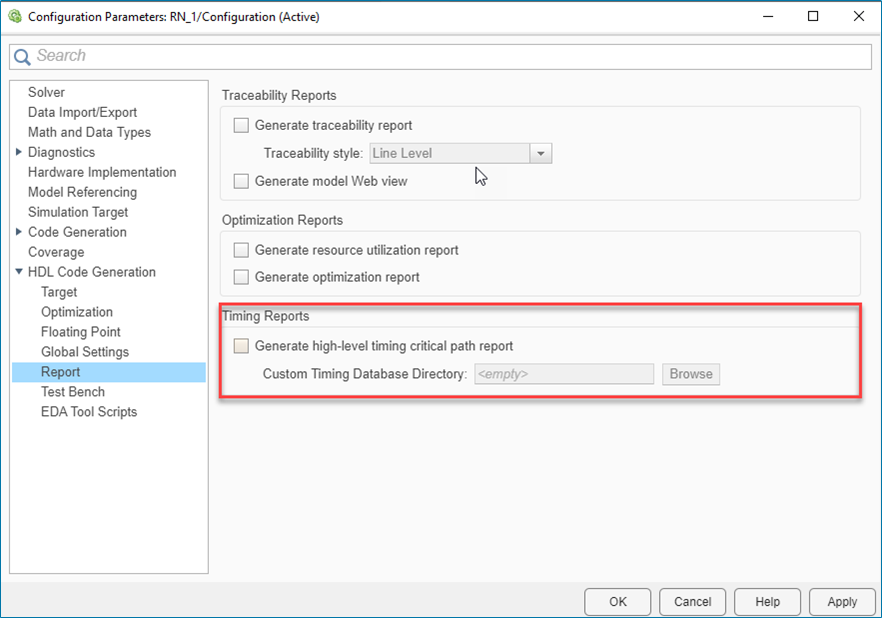
You can compute the critical path of your design by generating the high-level timing critical path report. For more information, see Critical Path Estimation Without Running Synthesis (R2022a).
In R2022a, HDL Coder has improved the critical path report to provide a more accurate timing estimation of the critical paths in your design. These enhancements are:
Blocks that supports custom latency for fixed-point and floating-point data types now participate in critical path estimation.
Blocks that use half-precision floating-point data types are marked as
'Block not characterized'. These blocks do not participate in critical path estimation.
You can generate the timing databases for the target device by using the genhdltdb (R2022a) function. In R2022a, HDL Coder has made these enhancements to the genhdltdb function:
A new name-value input argument
SynthesisDeviceConfigurationhas been added. You can now assign values such asDevice Family,Device Name,Device Package, andDevice Speed Gradein the single argument.For example, consider a Xilinx Artix - 7 target device, you can now specify target-specific information, such as device family, device name, device package and device speed grade, by using
SynthesisDeviceConfigurationargument ingenhdltdb.genhdltdb('SynthesisDeviceConfiguration',{'Artix7','xa7a100t','csg324','-1I'}, ... 'TimingDatabaseDirectory','C:\Work\Database', ... 'SynthesisToolName','Xilinx Vivado', ... 'SynthesisToolPath','C:\Xilinx\Vivado\2019.2\bin\vivado.bat');
Similarly, for a Xilinx Kintex UltraScale+ target device, where the device name includes device package and device speed grade. You can specify device family and device name, by using
SynthesisDeviceConfigurationargument ingenhdltdb.genhdltdb( 'SynthesisDeviceConfiguration',{'Kintex Ultrascale+','xcku11p-ffva1156-1-e'}, ... 'TimingDatabaseDirectory','C:\Work\Database', ... 'SynthesisToolName','Xilinx Vivado', ... 'SynthesisToolPath','C:\Xilinx\Vivado\2019.2\bin\vivado.bat');
The Custom Timing Database Directory in the HDL Configuration Parameters dialog box has command-line parameter name as
TimingDatabaseDirectory. To make the output path argument consistent with the Custom Timing Database Directory, the argument nameOutputPathhas changed toTimingDatabaseDirectory.The MAT files are generated in the path specified in
TimingDatabaseDirectoryargument value.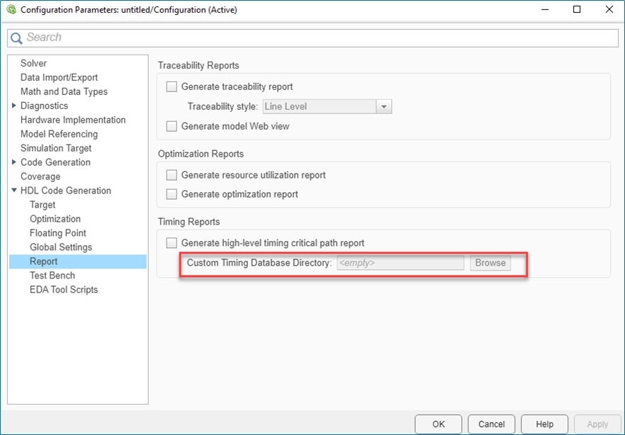
The argument name OutputPath is renamed to
TimingDatabaseDirectory.
Prior to R2022a, array indices might go out of bounds causing simulation to fail.
Array indices might go out of bounds due to the way ModelSim handles delta time step propagations. This image shows how a delta time step
propagation results in an out-of-bounds index value of -1 for the
variable idx.
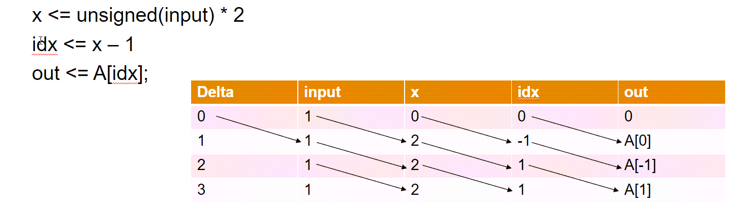
In R2022a, during simulation if you get a fatal error, for example
Fatal:(vsim-3421), you can enable an option to generate additional
logic that runs during simulation time to prevent array indices from going out of bounds.
See Suppress out-of-bounds access errors by generating simulation-only index
checks (R2022a).
Speed and Area Optimizations
In R2022a, the streaming and resource sharing optimizations have been improved:
For resource sharing, data type conversion is optimized when sharing signals with different fraction lengths.
Before R2022a, when sharing only signed signals with different fraction lengths, resource sharing produced an additional bit in the generated model and HDL code. Now, no additional bit is added when sharing only signed signals. For example, the synthesis results for a model sharing signed signals with different fraction lengths show a reduced number of dedicated logic registers used.
| Resource | Usage | |
|---|---|---|
| Before R2022a | R2022a | |
| Combinational Adaptive Look-Up Tables (ALUTs) | 36 | 36 |
| Dedicated logic registers | 622 | 611 |
| DSP blocks | 1 | 1 |
Before R2022a, when sharing only unsigned signals that had different fraction lengths,
resource sharing converted the unsigned signals to signed signals with
0 fraction length in the generated model and HDL code. Now, the
unsigned to signed conversion does not happen and the number of hardware resources used
are reduced. For example, the synthesis results for a model sharing unsigned signals with
different fraction lengths show a reduced number of dedicated logic registers and DSP
blocks used.
| Resource | Usage | |
|---|---|---|
| Before R2022a | R2022a | |
| Combinational ALUTs | 36 | 36 |
| Dedicated logic registers | 556 | 510 |
| DSP block 18-bit elements | 4 | 2 |
For resource sharing, you can now share signals with different signs and different word lengths through multiplier promotion.
For example, before R2022a, a generated model unable to share through multiplier promotion signals with different signs and word lengths looked like this figure.
Now, when you can share signals with different signs and word lengths through multiplier promotion, the generated model looks like this figure.
The synthesis results of the same model show that the number of DSP slices used is reduced from 2 to 1.
| Resource | Usage | |
|---|---|---|
| Before R2022a | R2022a | |
| Slice Look-up Tables (LUTs) | 68 | 121 |
| Slice Registers | 244 | 338 |
| DSPs | 2 | 1 |
To enable sharing through multiplier promotion, enable resource sharing for
multipliers for your subsystem and set the Multiplier promotion
threshold to an integer greater than 0, depending on the
word length difference between the signals that you want to share. For more information,
see the multiplier promotion threshold section of Resource Sharing Parameters for Adders and Multipliers (R2022a).
For streaming, more hardware resources are saved by not creating a streaming subnetwork for constant inputs. Now, constant inputs are not included in the streaming partition of the generated model and HDL code. For example, the resource utilization summary that HDL Coder estimated for a model with constant inputs and streaming enabled shows a reduction in multiple hardware resources used.
| Resource | Usage | |
|---|---|---|
| Before R2022a | R2022a | |
| Multipliers | 1 | 1 |
| Adders/Subtractors | 6 | 5 |
| Registers | 18 | 14 |
| Total 1-Bit Registers | 600 | 416 |
| Multiplexers | 22 | 17 |
For more information, see Resource Sharing (R2022a), Resource Sharing Settings for Various Blocks (R2022a), and Streaming (R2022a).
IP Core Generation and Hardware Deployment
The reference design workflow was supported for Xilinx and Intel based reference designs. HDL Coder has now added this reference design workflow for Microchip platforms. You can now use this reference design workflow on Microchip platforms, such as Polarfire SoC FPGA boards.
In R2021b, HDL Coder had added the IP Core Generation workflow support for the Microsemi Libero
SoC tool. It was supported only for Generic Microchip Platform
which generates IP core for a target-independent platform. In R2022a, you can now generate
IP core for a target-specific Microchip platform, such as Microchip PolarFire
SoC Icicle Kit, by using the reference design workflow.
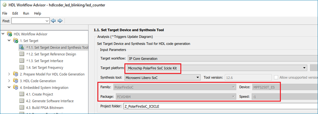
In the HDL Workflow Advisor task Set Target Device and Synthesis
Tool, you can now select the Target platform as
Microchip PolarFire SoC Icicle Kit for IP Core Generation
target workflow. For the Microchip PolarFire SoC Icicle Kit target platform, you can use
the Reference Design as the Default
System in task Set Target Reference Design.
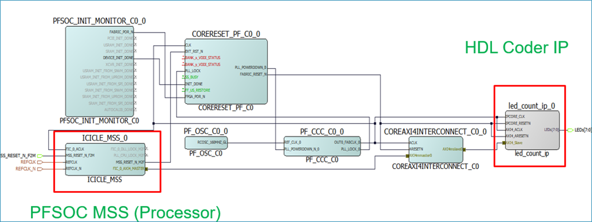
The figure shows the block design of default system reference design for the Microchip PolarFire SoC Icicle Kit target platform. The reference design workflow integrates your generated IP core with the other IPs such as processors and interfaces in the reference designs. You can generate bitstream for your design under test (DUT) and program the Polarfire SoC board for testing your DUT.
In the HDL Workflow Advisor, you can read back the AXI4 registers by using Enable readback on AXI4 slave write registers option in the task Generate RTL Code and IP Core. The readback is applied on the ports that are mapped to AXI4 registers.
In R2022a, HDL Coder has enhanced the AXI4 register readback functionality. You can now enable readback on AXI4 registers for the individual port. For better analysis of a complex design that has multiple ports, you can apply the readback option on selected ports to read values of the AXI4 write register. Use the Enable write register readback option for the individual port in HDL Workflow Advisor > Set Target Interface > Interface options to read values of the AXI4 write register.
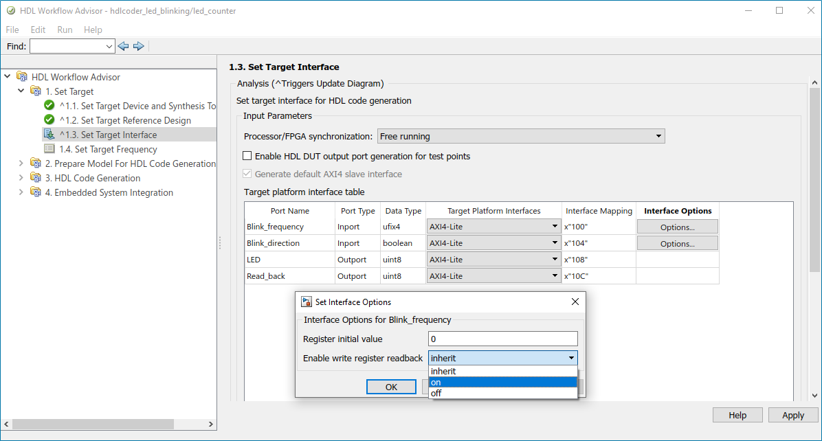
The Enable write register readback has these dropdown
options: inherit, on, and off.
The table lists the actions while using the Enable readback on AXI4 slave
write registers and Enable write register
readback options in the HDL Workflow Advisor.
Enable Readback on AXI4 Slave Write Registers (Global Readback Option) | Enable Write Register Readback (Port-Level Readback Option) | Readback Action for Individual Port |
| On | On | Enable |
| On | Off | Disable |
| Off | Inherit | Disable |
| Off | On | Enable |
| Off | Off | Disable |
| On | Inherit | Enable |
For more details, see Inspect the Written Values of AXI4 Slave Registers by Using the Readback Methods (R2022a).
Half-Precision data types are widely used in deep learning and control system applications. These data types require fewer FPGA resources compared to the single-precision. You can now use half-precision data types for various Simulink blocks.
In R2022a, HDL Coder provides half-precision support in IP Core Generation workflow. You can now
use half-precision data types for AXI4, AXI4-Lite, and AXI4 stream interfaces. In the
HDL Workflow Advisor > Set Target Interface, you can map the
half data types for the port with Target Platform
Interface set to AXI4,
AXI4-Lite, or AXI4 stream.
You can generate RTL code and an IP core for your design that use half-precision data types for AXI4, AXI4-Lite, and AXI4 stream interfaces. The half-precision data types for AXI4 interfaces are supported in Xilinx, Intel, and Microsemi IP core generation workflow. Ports that have bus or vector types also support half-precision data types for AXI4 and AXI4-Lite interfaces.
Simscape Hardware-in-the-Loop Workflow
Model and Architecture Design
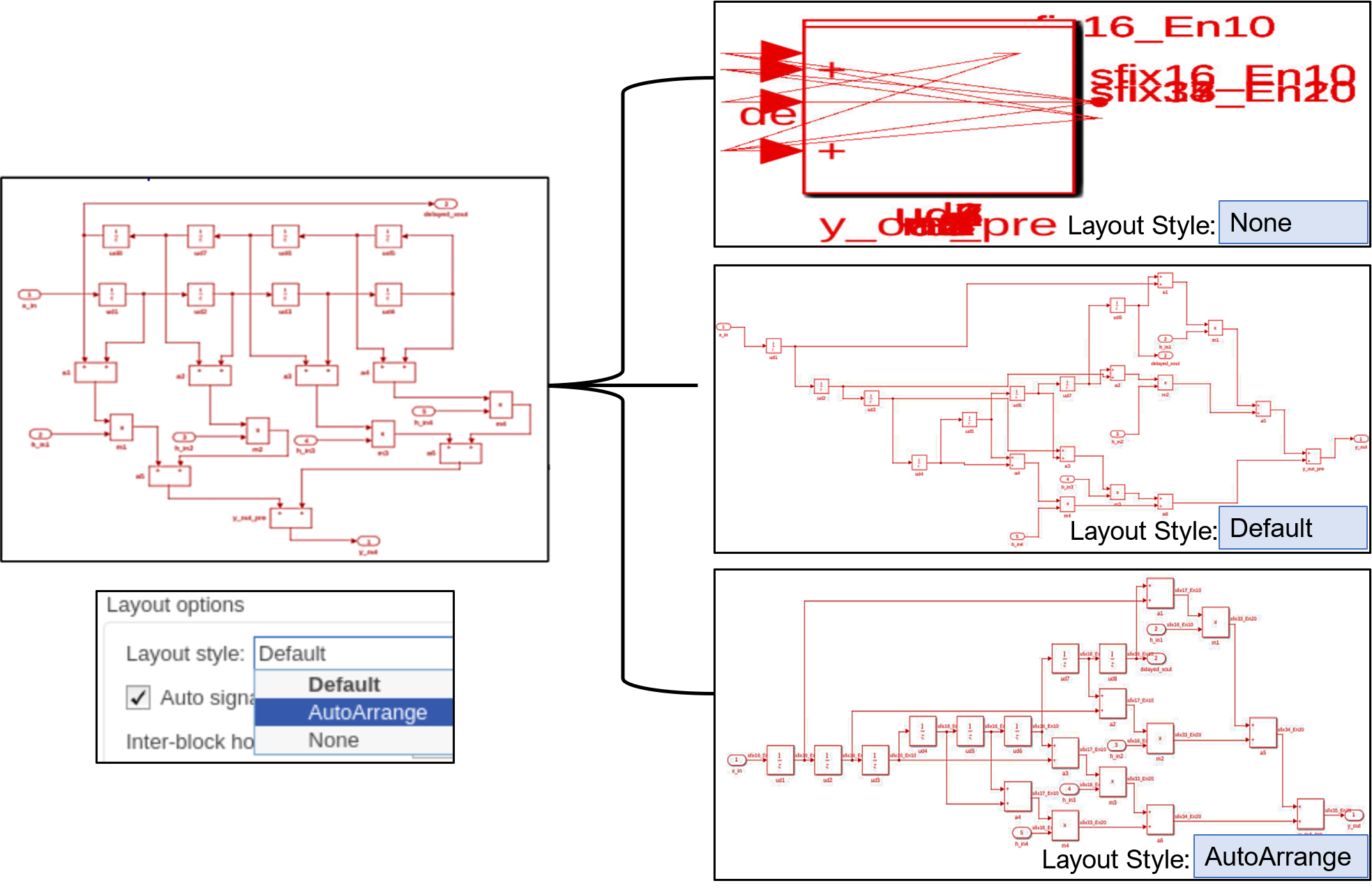
Starting in R2021b, the Layout style configuration parameter has been added to the Model generation pane in HDL Coder properties. You can now select the layout style for your generated model. The layout style has the options listed in this table:
| Layout Style | Description |
None | The generated model has no layout |
Default | The model is generated using the default HDL Coder layout |
AutoArrange | The model is generated using the Simulink layout |
For better layout visualization of your generated model, choose the appropriate layout style option based on the design complexity. You can identify these layout style effects in the generated model when you configure any optimization on your input model. For more information, see Layout Style (R2021b).
For example, see the generated layout of the input model that uses different layout style options.
Block Enhancements
In R2021b, the coding style for Reshape and Concat blocks has been improved. The generated HDL code has these coding style enhancements:
For Reshape and Concat blocks, the HDL code is generated with For-Generate loops when you select the target language as
VHDLorSystem Verilog.By default, the loop unrolled code is generated for the Reshape block the when target language is
Verilog.
The generated code has better code readability, reduced lines of code and reduced code
generation time. For example, this image shows code generated for the Reshape block with
For-Generate loops and without For-Generate
loops.

For more information, see Unroll For-Generate Loops in VHDL code (R2021b).
Pad the edge of a frame by reflecting around the edge-pixel value. This padding method helps reduce edge contrast effects and can improve results for machine learning while maintaining the original frame size.
To use this feature, set the Padding method parameter to
Reflection on any of these blocks.
Line Buffer (R2021b) (Vision HDL Toolbox)
Image Filter (R2021b) (Vision HDL Toolbox)
Bilateral Filter (R2021b) (Vision HDL Toolbox)
Median Filter (R2021b) (Vision HDL Toolbox)
Corner Detector (R2021b) (Vision HDL Toolbox)
For more information on padding methods, see Edge Padding (R2021b) (Vision HDL Toolbox).
Code Generation and Verification
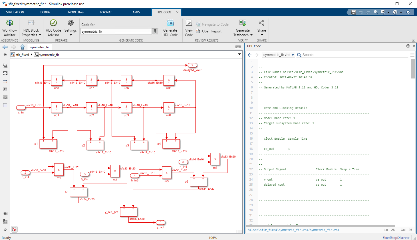
You can now view your generated HDL code alongside your model by using the Code view. Use this integration between code and model to:
Quickly navigate from model elements to their generated code. When you click on a block in the model, the Code view highlights the code for the block and scrolls to the highlighted code lines.
Trace lines of code to the model elements from which they were generated. In the Code view, click the line number hyperlink or code comment link to highlight the block that the code line traces to.
Customize your generated code and verify that the results are correct by viewing the code and the model at the same time.
After you generate HDL code for your model, the Code view displays the generated code to the right of your model. To manually open the Code view, on the Simulink toolstrip, click the View Code button. At the top of the Code view, select the file that you want to display. You can dock or undock the Code view from the editor and minimize or expand the Code view. You can also use rich text capabilities such as code folding and hiding comments.
Speed and Area Optimizations
In R2021b, HDL Coder inserts zero-protection switches that prevent input zeros from pipeline
initial values reaching blocks that do not work well with zero values. For example,
consider the following DUT and block-specific properties: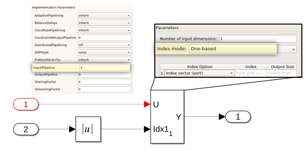
The DUT has one input pipeline register specified in the DUT's HDL Block parameters.
The selector blocks use one-based indexing, so a zero at the index port is an invalid
argument. Prior to R2021b, the generated model failed during simulation. In R2021b, for
the preceding model, you see a zero-protection switch is correctly applied in the
generated model and in the generated code. The simulation of the generated model is
successfully completed.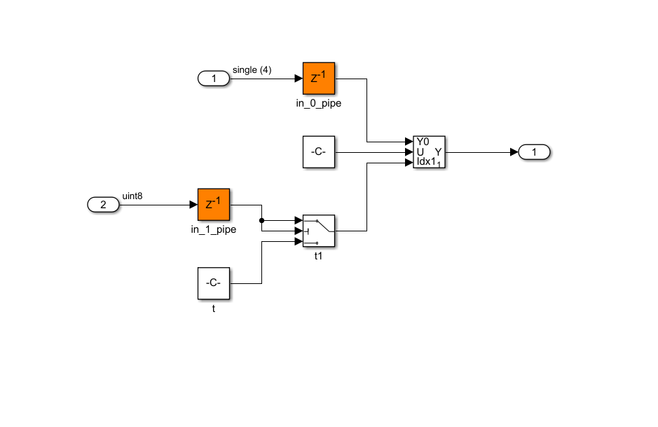
To avoid protection logic, minimize zeros feeding into blocks that do not expect zero run-time values.
In R2021b, HDL Coder performs optimizations during code generation to reduce area usage while
maintaining functionality and performance. For example, this figure shows the difference
in the generated code prior to R2021b and code generated in R2021b.