filterBuilder
(To be removed) Interactive filter design
filterBuilder will be removed in a future release. Use the Filter
Designer app or the designfilt function with no input arguments
instead.
Syntax
filterBuilder(h)

filterBuilder('response')
Description
filterBuilder starts an interactive tool for building filters. It
relies on the fdesign object-object oriented filter design
paradigm, and is intended to reduce development time during the filter design process.
filterBuilder uses a specification-centered approach to find
the best algorithm for the desired response.
Note
You must have the Signal Processing Toolbox™ installed to use fdesign and
filterBuilder. Some of the features described below may
be unavailable if your installation does not additionally include the
DSP System Toolbox™. You can verify the presence of both toolboxes by typing
ver at the command prompt.
To use filterBuilder, enter filterBuilder at
the MATLAB® command line using one of three approaches:
Simply enter
filterBuilder. MATLAB opens a dialog box for you to select a filter response type. After you select a filter response type,filterBuilderlaunches the appropriate filter design dialog box.Enter
filterBuilder(h), where h is an existing filter object. For example, ifhis a bandpass filter,filterBuilder(h)opens the bandpass filter design dialog box. Thehobject must have been created usingfilterBuilderor usingfdesign.Note
You must have the DSP System Toolbox software to create and import filter System objects.
Enter
filterBuilder('to replaceresponse')responsewith a response method from the following table. MATLAB opens a filter design dialog box that corresponds to the specified response.
Note
You must have the DSP System Toolbox software to implement a number of the filter designs listed in the following table. If you only have the Signal Processing Toolbox software, you can design a limited set of the following filter-response types.
| Response Method | Description of Resulting Filter Design |
|---|---|
arbgrpdelay | Arbitrary group delay filter design |
arbmag | Arbitrary magnitude filter design |
arbmagnphase | Arbitrary response filter (magnitude and phase) |
bandpass
or bp | Bandpass filter |
bandstop
or bs | Bandstop filter |
cic | CIC filter |
ciccomp | CIC compensator |
comb | Comb filter |
diff | Differentiator filter |
fracdelay | Fractional delay filter |
halfband
or hb | Halfband filter |
highpass
or hp | Highpass filter |
hilb | Hilbert filter |
isinc,
isinclp,
or
isinchp | Inverse sinc lowpass or highpass filter |
lowpass
or lp | Lowpass filter (default) |
notch | Notch filter |
nyquist | Nyquist filter |
octave | Octave filter |
peak | Peak filter |
Note
Because they do not change the filter structure, the magnitude specifications and
design method are tunable when using filterBuilder.
Filter Builder Design Panes
Main Design Pane
The main pane of Filter Builder varies depending on the filter response type, but the basic structure is the same. The following figure shows the basic layout of the dialog box.
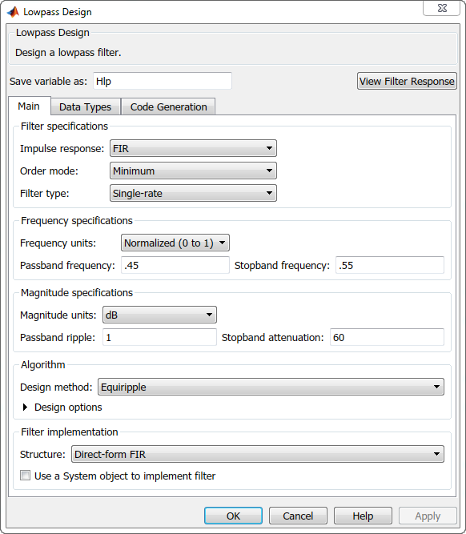
As you choose the response for the filter, the available options and design parameters displayed in the dialog box change. This display allows you to focus only on parameters that make sense in the context of your filter design.
Every filter design dialog box includes the options displayed at the top of the dialog box, shown in the following figure.
![]()
Save variable as — When you click Apply to apply your changes or OK to close this dialog box,
filterBuildersaves the current filter to your MATLAB workspace as a filter object with the name you enter.View Filter Response — Displays the magnitude response for the current filter specifications and design method. If you specify the input sample rate, the magnitude response is a function of frequency in Hz. If you do not specify the input sample rate, the magnitude response is a function of normalized frequency in rad/sample.
Note
The filterBuilder dialog box includes an
Apply option. Each time you click
Apply, filterBuilder writes
the modified filter to your MATLAB workspace. This modified filter has the
variable name you assign in Save variable as. To apply
changes without overwriting the variable in you workspace, change the
variable name in Save variable as before you click
Apply.
There are three tabs in the Filter Builder dialog box, containing three panes: Main, Data Types, and Code Generation. The first pane changes according to the filter being designed. The last two panes are the same for all filters. These panes are discussed in the following sections.
Data Types Pane
The second tab in the Filter Builder dialog box is shown in the following figure.

The Arithmetic drop down box allows the choice of
Double precision, Single
precision, or Fixed point. Some of
these options may be unavailable depending on the filter parameters. The following
table describes these options.
| Arithmetic List Entry | Effect on the Filter |
|---|---|
Double precision | All filtering operations and coefficients use
double-precision, floating-point representations and math. When
you use filterBuilder to create a filter,
double precision is the default
value for the Arithmetic property. |
Single precision | All filtering operations and coefficients use single-precision floating-point representations and math. |
Fixed point | This entry applies selected default values, typically used on
many digital processors, for the properties in the fixed-point
filter. These properties include coefficient word lengths,
fraction lengths, and various operating modes. This setting
allows signed fixed data types only. Fixed-point filter design
with filterBuilder is available only when you
install Fixed-Point Designer™ software along with DSP System Toolbox software. |
The following figure shows the Data Types pane after you
select Fixed point for Arithmetic
and set Filter internals to Specify
precision. This figure shows the Data Types pane
for the case where the Use a System object to implement filter
check box is not selected in the Main pane.

When you select Use a System object to implement filter check box in the Main pane, the Data Types pane appears as below:

Not all parameters described in the following section apply to all filters. For example, FIR filters do not have the Section input and Section output parameters.
- Input signal
Specify the format the filter applies to data to be filtered. For all cases,
filterBuilderimplements filters that use binary point scaling and signed input. You set the word length and fraction length as needed.- Coefficients
Choose how you specify the word length and the fraction length of the filter numerator and denominator coefficients:
Specify word lengthenables you to enter the word length of the coefficients in bits. In this mode,filterBuilderautomatically sets the fraction length of the coefficients to the binary-point only scaling that provides the best possible precision for the value and word length of the coefficients.Binary point scalingenables you to enter the word length and the fraction length of the coefficients in bits. If applicable, enter separate fraction lengths for the numerator and denominator coefficients.The filter coefficients do not obey the Rounding mode and Overflow mode parameters that are available when you select
Specify precisionfrom the Filter internals list. Coefficients are always saturated and rounded toNearest.
- Section Input
Choose how you specify the word length and the fraction length of the fixed-point data type going into each section of an SOS filter. This parameter is visible only when the selected filter structure is IIR and SOS.
Binary point scalingenables you to enter the word and fraction lengths of the section input in bits.Specify word lengthenables you to enter the word lengths in bits.
- Section Output
Choose how you specify the word length and the fraction length of the fixed-point data type coming out of each section of an SOS filter. This parameter is visible only when the selected filter structure is IIR and SOS.
Binary point scalingenables you to enter the word and fraction lengths of the section output in bits.Specify word lengthenables you to enter the output word lengths in bits.
- State
Contains the filter states before, during, and after filter operations. States act as filter memory between filtering runs or sessions. Use this parameter to specify how to designate the state word and fraction lengths. This parameter is not visible for direct form and direct form I filter structures because
filterBuilderdeduces the state directly from the input format. States always use signed representation:Binary point scalingenables you to enter the word length and the fraction length of the accumulator in bits.Specify precisionenables you to enter the word length and fraction length in bits (if available).
- Product
Determines how the filter handles the output of product operations. Choose from the following options:
Full precision— Maintain full precision in the result.Keep LSB— Keep the least significant bit in the result when you need to shorten the data words.Specify Precision— Enables you to set the precision (the fraction length) used by the output from the multiplies.
- Filter internals
Specify how the fixed-point filter performs arithmetic operations within the filter. The affected filter portions are filter products, sums, states, and output. Select one of these options:
Full precision— Specifies that the filter maintains full precision in all calculations for products, output, and in the accumulator.Specify precision— Set the word and fraction lengths applied to the results of product operations, the filter output, and the accumulator. Selecting this option enables the word and fraction length controls.
- Signed
Selecting this option directs the filter to use signed representations for the filter coefficients.
- Word length
Sets the word length for the associated filter parameter in bits.
- Fraction length
Sets the fraction length for the associate filter parameter in bits.
- Accum
Use this parameter to specify how you would like to designate the accumulator word and fraction lengths.
Determines how the accumulator outputs stored values. Choose from the following options:
Full precision— Maintain full precision in the accumulator.Keep MSB— Keep the most significant bit in the accumulator.Keep LSB— Keep the least significant bit in the accumulator when you need to shorten the data words.Specify Precision— Enables you to set the precision (the fraction length) used by the accumulator.
- Output
Sets the mode the filter uses to scale the output data after filtering. You have the following choices:
Avoid Overflow— Set the output data fraction length to avoid causing the data to overflow.Avoid overflowis considered the conservative setting because it is independent of the input data values and range.Best Precision— Set the output data fraction length to maximize the precision in the output data.Specify Precision— Set the fraction length used by the filtered data.
- Fixed-point operational parameters
Parameters in this group control how the filter rounds fixed-point values and how it treats values that overflow.
- Rounding mode
Sets the mode the filter uses to quantize numeric values when the values lie between representable values for the data format (word and fraction lengths).
ceil— Round toward positive infinity.convergent— Round to the closest representable integer. Ties round to the nearest even stored integer. This is the least biased of the methods available in this software.zero/fix— Round toward zero.floor— Round toward negative infinity.nearest— Round toward nearest. Ties round toward positive infinity.round— Round toward nearest. Ties round toward negative infinity for negative numbers, and toward positive infinity for positive numbers.
The choice you make affects everything except coefficient values and input data which always round. In most cases, products do not overflow—they maintain full precision.
- Overflow mode
Sets the mode the filter uses to respond to overflow conditions in fixed-point arithmetic. Choose from the following options:
Saturate— Limit the output to the largest positive or negative representable value.Wrap— Set overflowing values to the nearest representable value using modular arithmetic.
The choice you make affects everything except coefficient values and input data which always round. In most cases, products do not overflow—they maintain full precision.
- Cast before sum
Specifies whether to cast numeric data to the appropriate accumulator format before performing sum operations. Selecting Cast before sum ensures that the results of the affected sum operations match most closely the results found on most digital signal processors. Performing the cast operation before the summation adds one or two additional quantization operations that can add error sources to your filter results.
If you clear Cast before sum, the filter prevents the addends from being cast to the sum format before the addition operation. Choose this setting to get the most accurate results from summations without considering the hardware your filter might use. The input format referenced by Cast before sum depends on the filter structure you are using.
The effect of clearing or selecting Cast before sum is as follows:
Cleared — Configures filter summation operations to retain the addends in the format carried from the previous operation.
Selected — Configures filter summation operations to convert the input format of the addends to match the summation output format before performing the summation operation. Usually, selecting Cast before sum generates results from the summation that more closely match those found from digital signal processors.
Code Generation Pane
The code generation pane contains options for various implementations of the completed filter design. Depending on your installation, you can generate MATLAB code or create or update a Simulink® model from the designed filter. The following section explains these options.

- MATLAB
Generate MATLAB code based on filter specifications
Generate function that returns your filter as an output
Selecting this option generates a function that designs a filter object using
fdesign.Generate function that filters your data
Selecting this option generates a function that takes data as input, and outputs data filtered with the designed filter. The data type of the filter output is set according to the data type settings in the Data Types pane.
Clicking on the Generate MATLAB code button, brings up a Save File dialog box. Specify the file name and location, and save. The filter is now contained in an editable file.
- Simulink Model
Generate Simulink blocks and subsystems from your designed filters
When you click Generate Model, the filter builder generates Simulink blocks and subsystems from your designed filters.
Clicking on the Generate Model button opens the Export to Simulink dialog box.
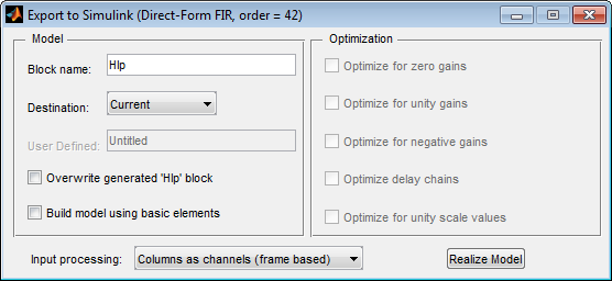
Block Name — The name for the new subsystem block, set to Filter by default.
Destination —
Currentsaves the generated model to the current Simulink model.Newcreates a new model to contain the generated block.User Definedcreates a new model or subsystem at the location specified inUser Defined.Overwrite generated 'Filter' block — Overwrites an existing block with the name specified in Block Name. Clear this check box to create a new block with the same name.
Build model using basic elements — Builds the model using only basic blocks.
Optimize for zero gains — Removes all zero-gain blocks from the model.
Optimize for unity gains — Replaces all unity gains with direct connections.
Optimize for negative gains — Removes all negative unity gain blocks, and changes sign at the nearest summation block.
Optimize delay chains — Replaces delay chains made up of n unit delays with a single delay by n.
Optimize for unity scale values — Removes all scale value multiplications by 1 from the filter structure.
Input processing — Specify how the generated filter block or subsystem block processes the input. Depending on the type of filter you are designing, one or both of the following options may be available:
Columns as channels (frame
                                                  based)
— The block treats each column of the input as a separate channel.Elements as channels (sample based)— The block treats each element of the input as a separate channel.
For more information about sample-based and frame-based processing, see Sample- and Frame-Based Concepts (DSP System Toolbox).
Realize Model — Builds the model with the set parameters.
When the Use a System object to implement filter check box is selected in the Main pane, the Generate Model button in the Simulink model panel is disabled under the following conditions:
Select Filter response as
Comband Arithmetic on the Data Types pane asFixed point.Select Filter response as
Arbitrary Response, Impulse response asIIR, set Specify response as to eitherMagnitudes and phasesorFrequency response, and Arithmetic on the Data Types pane asFixed point.
These settings design a
dsp.IIRFilterSystem object™ with fixed point arithmetic. Generating a Simulink model for fixed pointdsp.IIRFilterobject is not supported.
Filter Responses
Select your filter response from the filterBuilder
Response Selection main menu.
If you have the DSP System Toolbox software, the following Response Selection menu appears.
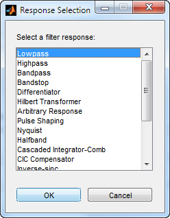
Select your desired filter response from the menu and design your filter.
The following sections describe the options available for each response type.