designfilt
R2026bDesign digital filter
Description
d = designfilt(response,Name=Value)digitalFilter object with response type
response. If you have a DSP System Toolbox™ license, you can also generate your design as a filter System object™. Examples of response are
"lowpassfir" and "bandstopiir".
Depending on how you specify response, you can set filter
specifications using a set of name-value arguments. If you specify an incomplete
or incorrect set of name-value arguments at the command line,
designfilt offers to open Filter Design Assistant to help you fix your code.
Use d to filter a signal or analyze the designed filter.
For example, use y = or
filter(d,x)y = to filter a signal
filtfilt(d,x)x. To visualize the filter d, use
Filter Analyzer.
For a list of filtering and analysis functions that you can use with a
digitalFilterobject, see Object Functions.For a list of filtering and analysis functions that you can use (since R2023b) with filter System objects, see Analysis Functions for Filter System Objects (DSP System Toolbox).
designfilt( lets you edit an
existing d)digitalFilter object d.
Alternatively, you can edit d using Filter Designer. The properties of the digitalFilter
object are otherwise read-only.
Examples
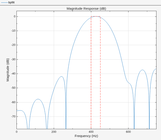
Design a 20th-order bandpass FIR filter with lower cutoff frequency 400 Hz and higher cutoff frequency 450 Hz. The sample rate is 1500 Hz.
bpfilt = designfilt("bandpassfir", ...
    FilterOrder=20,CutoffFrequency1=400, ...
    CutoffFrequency2=450,SampleRate=1500);
Visualize the magnitude response of the filter.
filterAnalyzer(bpfilt,SampleRate=1500)
Use bpfilt to filter a random signal containing 1000 samples.
dataIn = randn(1000,1);
dataOut = filter(bpfilt,dataIn);
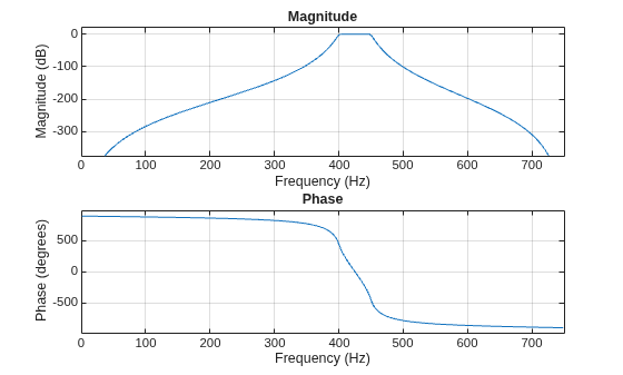
Design a 20th-order bandpass IIR filter with lower 3 dB frequency 400 Hz and higher 3 dB frequency 450 Hz. The sample rate is 1500 Hz.
bpfilt = designfilt("bandpassiir", ...
    FilterOrder=20,HalfPowerFrequency1=400, ...
    HalfPowerFrequency2=450,SampleRate=1500);
Visualize the frequency response of the filter.
freqz(bpfilt,[],1500)
Use it to filter a 1000-sample random signal.
dataIn = randn(1000,1);
dataOut = filter(bpfilt,dataIn);
Input Arguments
Filter response and type, specified as a character vector or string scalar.
FIR Specifications
response Value | Icon | Response |
|---|---|---|
"lowpassfir" | Lowpass FIR filter | |
"highpassfir" | Highpass FIR filter | |
"bandpassfir" | Bandpass FIR filter | |
"bandstopfir" | Bandstop FIR filter | |
"differentiatorfir" | Differentiator FIR filter | |
"hilbertfir" | Hilbert FIR filter | |
"complexlowpassfir" | Complex Lowpass FIR filter | |
"complexhighpassfir" | Complex Highpass FIR filter | |
'arbmagfir' | Arbitrary Response FIR filter |
DSP System Toolbox FIR Specifications
response Value | Icon | Description |
|---|---|---|
"arbmagnphasefir" | Arbitrary Response FIR filter | |
"isinclpfir" | Inverse sinc lowpass FIR filter | |
"isinchpfir" | Inverse sinc highpass FIR filter | |
"fracdelayfir" | Fractional-delay FIR filter |
IIR Specifications
response Value | Icon | Description |
|---|---|---|
"lowpassiir" | Lowpass IIR filter | |
"highpassiir" | Highpass IIR filter | |
"bandpassiir" | Bandpass IIR filter | |
"bandstopiir" | Bandstop IIR filter |
DSP System Toolbox IIR Specifications
response Value | Icon | Description |
|---|---|---|
"arbmagiir" | Arbitrary response IIR filter | |
"arbmagnphaseiir" | ||
"arbgrpdelayiir" | Arbitrary group delay IIR filter | |
"notchiir" | Multinotch IIR filter | |
"peakiir" | Multipeak IIR filter |
Select this option to design a Lowpass FIR filter. The
designfilt function supports these
design specifications.
| Filter Order Argument Names | Frequency Constraint Argument Names | Magnitude Constraint Argument Names | DesignMethod Argument Values | Design Option Argument Names |
|---|---|---|---|---|
N/A (Minimum-order design) |
| N/A | ||
| ||||
N/A |
| N/A | ||
N/A |
| |||
| ||||
N/A |
| |||
|
If you have a DSP System Toolbox license, the
designfilt function
supports (since R2023b) these additional design
specifications.
| Filter Order Argument Names | Frequency Constraint Argument Names | Magnitude Constraint Argument Names | DesignMethod Argument Values | Design Option Argument Names |
|---|---|---|---|---|
N/A (Minimum-order design) (since R2024a) |
| |||
N/A (Minimum-order design) (since R2025a) |
| |||
N/A (Minimum-order design) (since R2025a) |
|
| ||
| N/A |
| ||
|
| |||
|
| |||
| N/A | |||
| N/A | |||
| N/A | |||
| N/A |
|
Select this option to design a Lowpass IIR filter. The
designfilt function supports these
design specifications.
| Filter Order Argument Names | Frequency Constraint Argument Names | Magnitude Constraint Argument Names | DesignMethod Argument Values | Design Option Argument Names |
|---|---|---|---|---|
N/A (Minimum-order design) |
| |||
| ||||
| ||||
| ||||
N/A |
| N/A | ||
| N/A | |||
| N/A | |||
| N/A | |||
N/A |
| N/A |
If you have a DSP System Toolbox license, the
designfilt function
supports (since R2023b) these additional design
specifications.
| Filter Order Argument Names | Frequency Constraint Argument Names | Magnitude Constraint Argument Names | DesignMethod Argument Values | Design Option Argument Names |
|---|---|---|---|---|
N/A |
|
| ||
| N/A |
|
| |
|
| |||
| N/A |
|
| ||
|
| |||
|
| |||
|
| |||
| N/A |
|
|
Since R2026a
Select this option to design a Complex Lowpass FIR
filter. The designfilt function supports
these design specifications.
| Filter Order Argument Names | Frequency Constraint Argument Names | Magnitude Constraint Argument Names | DesignMethod Argument Values | Design Option Argument Names |
|---|---|---|---|---|
N/A |
| |||
N/A |
|
Since R2025a
Note
This response is available only if you have a DSP System Toolbox license.
Select this option to design an inverse sinc lowpass finite impulse response (FIR) filter. This example uses the first specification set from the table.
d = designfilt("isinclpfir", ...        % Response type
       PassbandFrequency=0.45, ...      % Frequency constraints
       StopbandFrequency=0.55 , ...
       PassbandRipple=1, ...
       StopbandAttenuation=60, ...
       DesignMethod="equiripple", ...   % Design method
       DensityFactor=16, ...            % Design options
       MinOrder="any", ...
       StopbandShape="flat", ...
       SincFrequencyFactor=0.5, ...
       SincPower=1, ...
       PhaseConstraint="linear", ...
       SystemObject=true)
The designfilt function supports these
design specifications.
| Filter Order Argument Names | Frequency Constraint Argument Names | Magnitude Constraint Argument Names | DesignMethod Argument Values | Design Option Argument Names |
|---|---|---|---|---|
N/A (Minimum-order design) |
| |||
N/A |
| |||
| ||||
| ||||
|
Select this option to design a Highpass FIR filter. The
designfilt function supports these
design specifications.
| Filter Order Argument Names | Frequency Constraint Argument Names | Magnitude Constraint Argument Names | DesignMethod Argument Values | Design Option Argument Names |
|---|---|---|---|---|
N/A (Minimum-order design) |
| N/A | ||
| ||||
N/A |
| N/A | ||
N/A |
| |||
| ||||
N/A |
| |||
|
If you have a DSP System Toolbox license, the
designfilt function
supports (since R2023b) these additional design
specifications.
| Filter Order Argument Names | Frequency Constraint Argument Names | Magnitude Constraint Argument Names | DesignMethod Argument Values | Design Option Argument Names |
|---|---|---|---|---|
N/A (Minimum-order design) (since R2024a) |
| |||
N/A (Minimum-order design) (since R2025a) |
| |||
N/A (Minimum-order design) (since R2025a) |
|
| ||
| N/A |
| ||
|
| |||
|
| |||
| N/A | |||
| N/A | |||
| N/A | |||
| N/A |
|
Select this option to design a Highpass IIR filter. The
designfilt function supports these
design specifications.
| Filter Order Argument Names | Frequency Constraint Argument Names | Magnitude Constraint Argument Names | DesignMethod Argument Values | Design Option Argument Names |
|---|---|---|---|---|
N/A (Minimum-order design) |
| |||
| ||||
| ||||
| ||||
N/A |
| N/A | ||
| N/A | |||
| N/A | |||
| N/A | |||
N/A |
| N/A |
If you have a DSP System Toolbox license, the
designfilt function
supports (since R2023b) these additional design
specifications.
| Filter Order Argument Names | Frequency Constraint Argument Names | Magnitude Constraint Argument Names | DesignMethod Argument Values | Design Option Argument Names |
|---|---|---|---|---|
N/A |
|
| ||
| N/A |
|
| |
|
| |||
| N/A |
|
| ||
|
| |||
|
| |||
|
| |||
| N/A |
|
|
Since R2026a
Select this option to design a Complex Highpass FIR
filter. The designfilt function supports
these design specifications.
| Filter Order Argument Names | Frequency Constraint Argument Names | Magnitude Constraint Argument Names | DesignMethod Argument Values | Design Option Argument Names |
|---|---|---|---|---|
N/A |
| |||
N/A |
|
Since R2025a
Note
This response is available only if you have a DSP System Toolbox license.
Select this option to design an inverse sinc highpass finite impulse response (FIR) filter. This example uses the first specification set from the table.
d = designfilt("isinchpfir", ...        % Response type
       StopbandFrequency=0.45 , ...     % Frequency constraints
       PassbandFrequency=0.55, ...
       PassbandRipple=1, ...            % Magnitude constraints
       StopbandAttenuation=60, ...
       DesignMethod="equiripple", ...   % Design method
       DensityFactor=16, ...            % Design options
       MinOrder="any", ...
       StopbandShape="flat", ...
       SincFrequencyFactor=0.5, ...
       SincPower=1, ...
       PhaseConstraint="linear", ...
       SystemObject=true)
| Filter Order Argument Names | Frequency Constraint Argument Names | Magnitude Constraint Argument Names | DesignMethod Argument Values | Design Option Argument Names |
|---|---|---|---|---|
N/A (Minimum-order design) |
| |||
N/A |
| |||
| ||||
| ||||
|
Select this option to design a Bandpass FIR filter. The
designfilt function supports these
design specifications.
| Filter Order Argument Names | Frequency Constraint Argument Names | Magnitude Constraint Argument Names | DesignMethod Argument Values | Design Option Argument Names |
|---|---|---|---|---|
N/A (Minimum-order design) |
| N/A | ||
| ||||
N/A |
| |||
| ||||
N/A |
| |||
|
If you have a DSP System Toolbox license, the
designfilt function
supports (since R2024a) these additional design
specifications.
| Filter Order Argument Names | Frequency Constraint Argument Names | Magnitude Constraint Argument Names | DesignMethod Argument Values | Design Option Argument Names |
|---|---|---|---|---|
N/A (Minimum-order design) |
| |||
| N/A |
| |||
| N/A |
| ||
|
Select this option to design a Bandpass IIR filter. The
designfilt function supports these
design specifications.
| Filter Order Argument Names | Frequency Constraint Argument Names | Magnitude Constraint Argument Names | DesignMethod Argument Values | Design Option Argument Names |
|---|---|---|---|---|
N/A (Minimum-order design) |
| |||
| ||||
| ||||
| ||||
N/A |
| N/A | ||
| N/A | |||
| N/A | |||
| N/A |
If you have a DSP System Toolbox license, the
designfilt function
supports (since R2024a) these additional design
specifications.
| Filter Order Argument Names | Frequency Constraint Argument Names | Magnitude Constraint Argument Names | DesignMethod Argument Values | Design Option Argument Names |
|---|---|---|---|---|
| N/A |
|
| |
|
| |||
|
| |||
|
| |||
|
| |||
| N/A |
|
| ||
| N/A |
|
|
Select this option to design a Bandstop FIR filter. The
designfilt function supports these
design specifications.
| Filter Order Argument Names | Frequency Constraint Argument Names | Magnitude Constraint Argument Names | DesignMethod Argument Values | Design Option Argument Names |
|---|---|---|---|---|
N/A (Minimum-order design) |
| N/A | ||
| ||||
N/A |
| |||
| ||||
N/A |
| |||
|
If you have a DSP System Toolbox license, the
designfilt function
supports (since R2024a) these additional design
specifications.
| Filter Order Argument Names | Frequency Constraint Argument Names | Magnitude Constraint Argument Names | DesignMethod Argument Values | Design Option Argument Names |
|---|---|---|---|---|
N/A (Minimum-order design) |
| |||
| N/A |
| |||
| N/A |
| ||
|
Select this option to design a Bandstop IIR filter. The
designfilt function supports these
design specifications.
| Filter Order Argument Names | Frequency Constraint Argument Names | Magnitude Constraint Argument Names | DesignMethod Argument Values | Design Option Argument Names |
|---|---|---|---|---|
N/A (Minimum-order design) |
| |||
| ||||
| ||||
| ||||
N/A |
| N/A | ||
| N/A | |||
| N/A | |||
| N/A |
If you have a DSP System Toolbox license, the
designfilt function
supports (since R2024a) these additional design
specifications.
| Filter Order Argument Names | Frequency Constraint Argument Names | Magnitude Constraint Argument Names | DesignMethod Argument Values | Design Option Argument Names |
|---|---|---|---|---|
| N/A |
|
| |
|
| |||
|
| |||
|
| |||
|
| |||
| N/A |
|
| ||
| N/A |
|
|
Since R2025a
Note
This response is available only if you have a DSP System Toolbox license.
Select this option to design a multi-notch IIR filter. This example uses the second specification set from the table.
d = designfilt("notchiir", ...
    FilterOrder=[6 6],CenterFrequency=[2.5 7.5], ...
    QualityFactor=[2.5 7.5],PassbandRipple=1, ...
    SampleRate=20,SystemObject=true);
d = designfilt("notchiir", ...
    NumNotches=10,NotchLocations="Harmonic", ...
    Bandwidth=0.125,BandwidthGain=-3, ...
    ShelvingFilterOrder=1,SystemObject=true);
designfilt function
supports these design specifications.| Filter Order Argument Names | Frequency Constraint Argument Names | Magnitude Constraint Argument Names | DesignMethod Argument Values | |
|---|---|---|---|---|
| N/A |
| ||
|
| |||
|
| |||
|
| |||
| N/A |
| ||
|
| |||
|
| |||
|
| |||
|
| |||
Since R2025a
Note
This response is available only if you have a DSP System Toolbox license.
Select this option to design a multi-peak IIR filter. This example uses the second specification set from the table.
d = designfilt("peakiir", ...
    FilterOrder=[6 6],CenterFrequency=[2.5 7.5], ...
    QualityFactor=[2.5 7.5],PassbandRipple=1, ...
    SampleRate=20,SystemObject=true);
d = designfilt("peakiir", ...
    NumPeaks=10,PeakLocations="Harmonic", ...
    Bandwidth=0.125,BandwidthGain=-3, ...
    ShelvingFilterOrder=1,SystemObject=true);
designfilt function
supports these design specifications.| Filter Order Argument Names | Frequency Constraint Argument Names | Magnitude Constraint Argument Names | DesignMethod Argument Values | |
|---|---|---|---|---|
| N/A |
| ||
|
| |||
|
| |||
|
| |||
| N/A |
| ||
|
| |||
|
| |||
|
| |||
|
| |||
Select this option to design a Differentiator FIR filter. The
designfilt function supports these
design specifications.
| Filter Order Argument Names | Frequency Constraint Argument Names | Magnitude Constraint Argument Names | DesignMethod Argument Values | Design Option Argument Names |
|---|---|---|---|---|
N/A | N/A |
| N/A | |
| N/A | |||
N/A |
| |||
| N/A |
If you have a DSP System Toolbox license, the
designfilt function
supports (since R2025a) these additional design
specifications.
| Filter Order Argument Names | Frequency Constraint Argument Names | Magnitude Constraint Argument Names | DesignMethod Argument Values | Design Option Argument Names |
|---|---|---|---|---|
N/A (Minimum-order design) |
|
Select this option to design a Hilbert FIR filter. The
designfilt function supports these
design specifications.
| Filter Order Argument Names | Frequency Constraint Argument Names | Magnitude Constraint Argument Names | DesignMethod Argument Values | Design Option Argument Names |
|---|---|---|---|---|
N/A |
| N/A | ||
| N/A |
If you have a DSP System Toolbox license, the
designfilt function
supports (since R2025a) these additional design
specifications.
| Filter Order Argument Names | Frequency Constraint Argument Names | Magnitude Constraint Argument Names | DesignMethod Argument Values | Design Option Argument Names |
|---|---|---|---|---|
N/A (Minimum-order design) |
|
Select this option to design a finite impulse response (FIR)
filter of arbitrary magnitude response. For more information,
see Arbitrary Response FIR. The
designfilt function supports these
design specifications.
| Filter Order Argument Names | Frequency Constraint Argument Names | Magnitude Constraint Argument Names | DesignMethod Argument Values | Design Option Argument Names |
|---|---|---|---|---|
| ||||
| ||||
| ||||
… | … |
| … | |
| … |
If you have a DSP System Toolbox license, the
designfilt function
supports (since R2025a) these additional design
specifications.
| Filter Order Argument Names | Frequency Constraint Argument Names | Magnitude Constraint Argument Names | DesignMethod Argument Values | Design Option Argument Names |
|---|---|---|---|---|
| ||||
… | … |
| … | |
… | … … … | "equiripple" | … … | |
N/A (Minimum-order design) |
| |||
N/A (Minimum-order design) | … | … … |
| … |
Since R2025a
Note
This response is available only if you have a DSP System Toolbox license.
Select this option to design an infinite impulse response (IIR) filter of arbitrary magnitude response. This example uses the first specification set from the table.
d = designfilt("arbmagiir", ...
    FilterOrder=20,Frequencies=linspace(0,1,30), ...
    Amplitudes=[ones(1,7) zeros(1,8) ones(1,8) zeros(1,7)], ...
    SystemObject=true);
designfilt function supports these
design specifications.| Filter Order Argument Names | Frequency Constraint Argument Names | Magnitude Constraint Argument Names | DesignMethod Argument Values | Design Option Argument Names |
|---|---|---|---|---|
|
| |||
… | … |
| …
|
Since R2025a
Note
This response is available only if you have a DSP System Toolbox license.
Select this option to design a finite impulse response (FIR)
filter of arbitrary magnitude and phase responses. For more
information, see Arbitrary Response FIR. The
designfilt function supports these
design specifications.
| Filter Order Argument Names | Frequency Constraint Argument Names | Magnitude Constraint Argument Names | DesignMethod Argument Values | Design Option Argument Names |
|---|---|---|---|---|
FrequencyResponse | "equiripple" | |||
FrequencyResponse | "ls" | |||
FrequencyResponse | "freqsamp" | |||
… | … | "equiripple" | … | |
… | … | "ls" | … |
Since R2025a
Note
This response is available only if you have a DSP System Toolbox license.
Select this option to design an infinite impulse response (IIR) filter of arbitrary magnitude and phase responses. This example uses the specification set from the table.
d = designfilt("arbmagnphaseiir", ...
        FilterOrder=20, ...
        Frequencies=[0 0.25 1], ...
        FrequencyResponse=[complex(1,2) complex(3,4) complex(5,6)], ...
        DesignMethod="ls")
designfilt function
supports these design specifications.| Filter Order Argument Names | Frequency Constraint Argument Names | Magnitude Constraint Argument Names | DesignMethod Argument Values | Design Option Argument Names |
|---|---|---|---|---|
FrequencyResponse |
| |||
FrequencyResponse |
|
Since R2025a
Note
This response is available only if you have a DSP System Toolbox license.
Select this option to design an infinite impulse response (IIR) filter of arbitrary group delay. This example uses the first specification set from the table.
d = designfilt("arbgrpdelayiir", ...
    FilterOrder=20,Frequencies=linspace(0,1,30), ...
    GroupDelayResponse=[10*ones(1,15) linspace(10,1,15)], ...
    SystemObject=true);
designfilt function
supports these design specifications.| Filter Order Argument Names | Frequency Constraint Argument Names | Magnitude Constraint Argument Names | DesignMethod Argument Values | Design Option Argument Names |
|---|---|---|---|---|
|
| |||
… | … |
| …
|
Since R2025a
Note
This response is available only if you have a DSP System Toolbox license.
Select this option to design a fractional delay FIR filter.
d = designfilt("fracdelayfir", ...
    FilterOrder=45,FractionalDelay=0.6, ...
    SampleRate=20,SystemObject=true);
designfilt function
supports these design specifications.| Filter Order Argument Names | Frequency Constraint Argument Names | Magnitude Constraint Argument Names | DesignMethod Argument Values | Design Option Argument Names | |
|---|---|---|---|---|---|
N/A | N/A | N/A | |||
N/A | N/A | N/A | |||
Data Types: char | string
Digital filter, specified as a digitalFilter object
generated by designfilt. Use this input to change the
specifications of an existing digitalFilter.
Name-Value Arguments
Specify optional pairs of arguments as
Name1=Value1,...,NameN=ValueN, where Name is
the argument name and Value is the corresponding value.
Name-value arguments must appear after other arguments, but the order of the
pairs does not matter.
Example: FilterOrder=20,CutoffFrequency=0.4 suffices to specify
a lowpass FIR filter.
Available specifications are response dependent and include combinations of these:
Sample Rate is the frequency at which the filter operates. If you do not specify a sample rate, then
designfiltassumes normalized frequencies.Filter Order: Some design methods let you specify the order. Others produce minimum-order designs. That is, they generate the smallest filters that satisfy the specified constraints.
Frequency Constraints correspond to the frequencies at which a filter exhibits a desired behavior. Examples include
PassbandFrequencyandCutoffFrequency. You must always specify the frequency constraints.Magnitude Constraints describe the filter behavior at particular frequency ranges. Examples include
PassbandRippleandStopbandAttenuation.designfiltprovides default values for magnitude constraints left unspecified. In arbitrary-magnitude designs you must always specify the vectors of desired amplitudes.Design Method is the algorithm used to design the filter. Examples include equiripple FIR filter design using the Parks-McClellan algorithm (
"equiripple") and Butterworth ("butter"). For some specification sets, there are multiple design methods available to choose from. In other cases, you can use only one method to meet the desired specifications.Design Method Options are parameters specific to a given design method. Examples include
Windowfor the"window"method and optimizationWeightsfor arbitrary-magnitude equiripple designs.designfiltprovides default values for design options left unspecified.Implementation parameters determine how
designfiltimplements the filter design, whether as adigitalFilterobject, a filter System object, or CTF coefficient matrices. (since R2027a)
Sample Rate
Sample rate, specified as a positive scalar expressed in hertz. If you
do not specify SampleRate, then
designfilt assumes normalized
frequencies.
Data Types: double
Filter Order
Filter order, N, specified as a positive integer.
Data Types: double
Numerator order for IIR filters, specified as a positive integer.
Data Types: double
Denominator order for IIR filters, specified as a positive integer.
Data Types: double
Since R2025a
Source of notch frequencies, specified as one of these:
"Specify"–– Specify the notch center frequencies using theCenterFrequencyproperty."Harmonic"–– Attenuate a set of harmonically related frequencies using a comb filter. Specify the number of harmonics using theNumNotchesproperty.
This argument applies only when you set the filter response to
"notchiir".
Data Types: double
Since R2025a
Number of harmonic notches in the two-sided spectrum, specified as a positive integer. The function uses this value to determine the number of harmonically related notch frequencies in the comb filter.
This argument applies only when you set the filter response to
"notchiir" and
NotchLocations to
"Harmonic".
Data Types: double
Since R2025a
Source of peak frequencies, specified as one of these:
"Specify"–– Specify the peak center frequencies using theCenterFrequencyproperty."Harmonic"–– Amplify a set of harmonically related frequencies using a comb filter. Specify the number of harmonics using theNumPeaksproperty.
This argument applies only when you set the filter response to
"peakiir".
Data Types: double
Since R2025a
Number of harmonic peaks in the two-sided spectrum, specified as a positive integer. The function uses this value to determine the number of harmonically related peak frequencies in the comb filter.
This argument applies only when you set the filter response to
"peakiir" and PeakLocations
to "Harmonic".
Data Types: double
Since R2025a
Shelving filter order Nsh,
specified as a positive integer. The shelving filter order determines
the sharpness of the peaks or notches. The greater the value of the
shelving filter order, the steeper the slope of the peak or notch. The
order of the notching or peaking filter is given by
L×Nsh,
where L is the number of notches or peaks you specify
using NumNotches or
NumPeaks.
This argument applies only when you set:
Filter response to
"notchiir"or"peakiir".NotchLocationsorPeakLocationsto"Harmonic".
Data Types: double
Frequency Constraints
Passband frequency, specified as a positive scalar. The frequency value must be within the Nyquist range.
PassbandFrequency1 is the lower passband frequency for a bandpass or
bandstop design.
PassbandFrequency2 is the higher passband frequency for a bandpass or
bandstop design.
Data Types: double
Stopband frequency, specified as a positive scalar. The frequency value must be within the Nyquist range.
StopbandFrequency1 is the lower stopband frequency for a bandpass or
bandstop design.
StopbandFrequency2 is the higher stopband frequency for a bandpass or
bandstop design.
Data Types: double
6 dB frequency, specified as a positive scalar. The frequency value must be within the Nyquist range.
CutoffFrequency1 is the lower 6 dB frequency for a bandpass or bandstop
design.
CutoffFrequency2 is the higher 6 dB frequency for a bandpass or bandstop
design.
Data Types: double
3 dB frequency, specified as a positive scalar. The frequency value must be within the Nyquist range.
HalfPowerFrequency1 is the lower 3 dB frequency for a bandpass or
bandstop design.
HalfPowerFrequency2 is the higher 3 dB frequency for a bandpass or
bandstop design.
Data Types: double
Bandwidth of the filter passband in normalized frequency units,
specified as a positive scalar less than the difference between
HalfPowerFrequency2 and HalfPowerFrequency1.
Dependencies
This property applies only if you set the filter response to
"bandpassiir" or
"bandstopiir".
Data Types: double
Frequency width between the two stopband frequencies, specified as a positive scalar.
Dependencies
This property applies only if you set the filter response to
"bandpassiir" or
"bandstopiir".
Data Types: double
Width of the transition region between passband and stopband for a Hilbert transformer or for a complex FIR filter, specified as a positive scalar.
Data Types: double
Response frequencies, specified as a vector. Use this variable to list the frequencies at
which a filter of arbitrary magnitude and phase responses has desired
amplitudes and phase values. The frequencies must be monotonically
increasing and lie within the Nyquist range. The first element of the
vector must be either 0 or –fs/2, where fs is the sample rate, and its last element must be fs/2. If you do not specify a sample rate,
designfilt uses the default value of 2
Hz.
Data Types: double
Since R2025a
Frequency response values, specified as a vector. Use this argument to
specify the arbitrary magnitude and phase response values at the
frequencies you specify in the Frequencies
argument. The length of this vector must equal the length of the
Frequencies vector.
Data Types: double
Complex Number Support: Yes
Since R2025a
Group delay response values, specified as a vector. Use this variable
to specify the group delay response values at the frequencies you
specify in the Frequencies argument. The length of
this vector must equal the length of the
Frequencies vector.
Data Types: double
Number of bands in a multiband design, specified as a positive integer scalar not greater than 10.
Data Types: double
Multiband response frequencies, specified as numeric vectors.
BandFrequenciesi, where i runs from 1 through NumBands, is
a vector containing the frequencies at which the ith band of a multiband design has the desired values,
BandAmplitudesi,
BandFrequencyResponsei,
BandGroupDelayResponsei.
NumBands must not exceed 10. The frequencies
must lie within the Nyquist range and must be specified in monotonically
increasing order. Adjacent frequency bands must have the same amplitude
at their junction.
Data Types: double
Since R2025a
Multiband group delay response values, specified as numeric vectors.
BandGroupDelayResponsei, where i runs from 1 through NumBands, is
a vector containing the group delay response values in the ith band specified at the frequency values given by
BandFrequenciesi. NumBands
can be at most 10.
Data Types: double
Since R2025a
Center frequency f0 of the notch or peak IIR filter, specified as a scalar or a vector. The center frequency values must be in the range 0 < f0 < fs/2.
When specified as a vector, the length of this argument must be equal
to the length of the FilterOrder and
QualityFactor arguments. If you specify the
input sample rate through the SampleRate property,
then specify the value of the center frequency in Hz.
This argument applies only when you set the filter response to
"notchiir" or
"peakiir".
Data Types: double
Since R2025a
Quality factor q of the notch or peak IIR filter,
specified as a positive scalar or a vector. When specified as a vector,
the length of this argument must be equal to the length of the
CenterFrequency argument.
Quality factor of the filter is defined as the ratio of the lowest center frequency of the peak or notch f0 (not including DC) to the 3 dB bandwidth BW calculated at the −3 dB point, and is given by q = f0/BW.
This argument applies only when you set the filter response to
"notchiir" or
"peakiir".
Data Types: double
Since R2025a
3 dB bandwidth BW of the notch or peak IIR filter, specified as a scalar or a vector.
When you set NotchLocations or
PeakLocations to:
"Specify"–– The bandwidth must be a numeric scalar or a vector equal in length toNumNotchesorNumPeaksargument. The bandwidth value must be in the range 0 < BW < fs/2."Harmonic"–– The bandwidth must be a numeric scalar in the range 0 < BW < fs/(2 ×NumNotchesorNumPeaks).
By default, the function calculates the bandwidth at the point –3 dB from the center frequency of the peak or notch. For example, setting BW to 0.01 specifies that the –3 dB point will be +/− 0.005 (in normalized frequency) from the center of the notch or peak.
This argument applies only when you set the filter response to
"notchiir" or
"peakiir".
Data Types: double
Since R2026a
Response at zero frequency for multi-notch IIR filters, specified as one of these:
"Notch"— Notch at the zero frequency."Passband"— Passband at the zero frequency.
To enable this property, set the filter response to
"notchiir".
Data Types: char | string
Since R2026a
Response at zero frequency for multi-peak IIR filters, specified as one of these:
"Peak"— Peak at the zero frequency."Stopband"— Stopband at the zero frequency.
To enable this property, set the filter response to
"peakiir".
Data Types: char | string
Since R2025a
Target combined bandwidth, specified as a positive scalar less than 0.999×fs/2, where fs is the input sample rate. This is the value of the combined bandwidth that the design must satisfy. Combined bandwidth is defined as the minimum of the gain bandwidth (DSP System Toolbox) and the group delay bandwidth (DSP System Toolbox).
Specifying both filter length and target combined bandwidth results in an overdetermined design. The filter design does not support specifying both values. When you specify the target combined bandwidth, the algorithm determines the corresponding filter length and designs the filter accordingly.
Specify a higher target combined bandwidth for a longer filter. For example, setting the bandwidth to 0.9 × fs/2 yields a filter of length of 52, while increasing the bandwidth to 0.99 × fs/2 yields a length of 724, which is more than 10 times longer. As bandwidth tends towards fs/2, the filter length theoretically tends towards infinity.
This argument applies only when you set the filter response to
"fracdelayfir".
Data Types: double
Magnitude Constraints
Passband ripple, specified as a positive scalar expressed in decibels.
PassbandRipple1 is the lower-band passband ripple
for a bandstop design.
PassbandRipple2 is the higher-band passband
ripple for a bandstop design.
Data Types: double
Stopband attenuation, specified as a positive scalar expressed in decibels.
StopbandAttenuation1 is the lower-band stopband
attenuation for a bandpass design.
StopbandAttenuation2 is the higher-band stopband
attenuation for a bandpass design.
Data Types: double
Since R2024a
Option to constrain passband ripple, specified as a logical value.
Set Passband1Constrained to
true to constrain the first passband ripple in
the bandstop FIR filter.
Set Passband2Constrained to
true to constrain the second passband ripple in
the bandstop FIR filter.
Set PassbandConstrained to
true to constrain the passband ripple in the
bandpass FIR filter.
Data Types: logical
Since R2024a
Option to constrain stopband attenuation, specified as a logical value.
Set Stopband1Constrained to
true to constrain the first stopband attenuation
in the bandpass FIR filter.
Set Stopband2Constrained to
true to constrain the second stopband attenuation
in the bandpass FIR filter.
Set StopbandConstrained to
true to constrain the stopband attenuation in the
bandstop FIR filter.
Data Types: logical
Desired response amplitudes of an arbitrary magnitude response filter,
specified as a vector. Express the amplitudes in linear units. The
vector must have the same length as
Frequencies.
Data Types: double
Multiband response amplitudes, specified as numeric vectors.
BandAmplitudesi, where i runs from 1 through NumBands, is
a vector containing the desired amplitudes in the ith band of a multiband design.
NumBands can be at most 10. Express the
amplitudes in linear units. BandAmplitudesi must
have the same length as BandFrequenciesi. Adjacent
frequency bands must have the same amplitude at their junction.
Data Types: double
Since R2025a
Option to set constrained multiband, specified as logical vectors.
This argument enables you to constrain the passband ripple in your
multiband design. You cannot constrain the passband ripple in all bands
simultaneously. BandConstrainedi, where i runs from 1 through NumBands, is
a vector that specifies if the corresponding ith band of a multiband design is constrained.
NumBands can be at most 10.
BandConstrainedi must have the same length as
BandAmplitudesi and
BandFrequenciesi.
Data Types: logical
Since R2025a
Multiband response passband ripples, specified as sets of positive
scalars or of vectors. BandRipplei, where i runs from 1 through NumBands, is
a scalar or vector containing the desired passband ripple of the ith band of a multiband design.
NumBands can be at most 10. If specified as a
vector, BandRipplei must have the same length as
BandAmplitudesi and
BandFrequenciesi.
Data Types: double
Since R2025a
Multiband frequency response values, specified as numeric vectors.
BandFrequencyResponsei, where i runs from 1 through NumBands, is
a vector containing the frequency response values in the ith band specified at the frequency values given by
BandFrequenciesi. NumBands
must not exceed 10.
Data Types: double
Complex Number Support: Yes
Since R2025a
Gain at which the bandwidth is measured, specified as a scalar. This argument allows you specify the bandwidth of the notch or peak at a gain different from the –3 dB default.
This argument applies only when you set:
The filter response to
"notchiir"or"peakiir".The
NotchLocationsorPeakLocationsto"Harmonic".
Data Types: double
Design Method
Design method, specified as a character vector or string scalar. The choice of design method depends on the set of frequency and magnitude constraints that you specify.
"butter"designs a Butterworth IIR filter. Butterworth filters have a smooth monotonic frequency response that is maximally flat in the passband. They sacrifice rolloff steepness for flatness."cheby1"designs a Chebyshev type I IIR filter. Chebyshev type I filters have a frequency response that is equiripple in the passband and maximally flat in the stopband. Their passband ripple increases with increasing rolloff steepness."cheby2"designs a Chebyshev type II IIR filter. Chebyshev type II filters have a frequency response that is maximally flat in the passband and equiripple in the stopband."cls"designs an FIR filter using constrained least squares. The method minimizes the discrepancy between a specified arbitrary piecewise-linear function and the filter’s magnitude response. At the same time, it lets you set constraints on the passband ripple and stopband attenuation."ellip"designs an elliptic IIR filter. Elliptic filters have a frequency response that is equiripple in both passband and stopband."equiripple"designs an equiripple FIR filter using the Parks-McClellan algorithm. Equiripple filters have a frequency response that minimizes the maximum ripple magnitude over all bands."freqsamp"designs an FIR filter of arbitrary magnitude response by sampling the frequency response uniformly and taking the inverse Fourier transform."kaiserwin"designs an FIR filter using the Kaiser window method. The method truncates the impulse response of an ideal filter and uses a Kaiser window to attenuate the resulting truncation oscillations."lpnorm"designs a least Pth-norm optimal IIR filter using the least-Pth unconstrained optimization algorithm. For more information, see Least Pth-Norm Optimal IIR Filter Design (DSP System Toolbox). (since R2023b)Note
To use the
"lpnorm"design method, you must have a valid DSP System Toolbox license."ls"designs an FIR filter using least squares. The method minimizes the discrepancy between a specified arbitrary piecewise-linear function and the filter’s magnitude response."maxflat"designs a maximally flat FIR filter. These filters have a smooth monotonic frequency response that is maximally flat in the passband."window"uses a least-squares approximation to compute the filter coefficients and then smooths the impulse response withWindow."ifir"designs an interpolated FIR filter. Interpolated FIR filters are narrowband FIR filters with relatively lower filter orders. To achieve an efficient design that reduces the total number of required multipliers, the"ifir"design algorithm splits the design problem into two stages. In the first stage, the filter is upsampled to achieve the stringent specifications without using many multipliers. In the second stage, the filter removes the images created when upsampling the previous filter. (since R2025a)Note
To use the
"ifir"design method, you must have a valid DSP System Toolbox license.
Data Types: char | string
Design Method Options
Since R2025a
Type of the linear-phase FIR filter, specified as one of these:
"1"–– Even-order and symmetric FIR filter"2"–– Odd-order and symmetric FIR filter"3"–– Even-order and antisymmetric FIR filter"4"–– Odd-order and antisymmetric FIR filter
This argument applies only when you set the filter response to
"hilbertfir".
Data Types: char | string
Minimum order parity of a "kaiserwin" design or an
"equiripple" design, specified as
"any", "even", or
"odd".
When you set MinOrder to:
"any"–– The returned filter can have even or odd order, whichever is smaller."even"––designfiltreturns a minimum-order filter with even order."odd"––designfiltreturns a minimum-order filter with odd order.
Data Types: char | string
Window, specified as a vector of length N + 1, where N is the filter order. Window can
also be paired with a window name or function handle that specifies the
function used to generate the window. Any such function must take N + 1 as first input. Additional inputs can be passed by
specifying a cell array. By default, Window is an
empty vector for the "freqsamp" design method and
@hamming for the "window"
design method.
For a list of available windows, see Windows.
Example: Window=hann(N+1) and
Window=(1-cos(2*pi*(0:N)'/N))/2 both specify a
Hann window to use with a filter of order
N.
Example: Window="hamming" specifies a Hamming window
of the required order.
Example: Window=@mywindow lets you define your own
window function.
Example: Window={@kaiser,0.5} specifies a Kaiser
window of the required order with shape parameter 0.5.
Data Types: double | char | string | function_handle | cell
Band to match exactly, specified as "stopband",
"passband", or "both".
"both" is available only for the elliptic design
method, where it is the default. "stopband" is the
default for the "butter" and
"cheby2" methods. "passband"
is the default for "cheby1".
Data Types: char | string
Since R2023b
L-infinity norm, specified as a positive scalar.
This argument applies only when you set
DesignMethod to
"lpnorm".
Data Types: double
Since R2026a
Option to scale the filter coefficients representing second-order
sections (SOS), specified as a logical scalar. When you set this
parameter to true, the function scales the SOS
coefficients using the L-infinity norm scaling, so
that the filter has unit gain at zero frequency.
This argument applies to IIR filter design responses.
Data Types: logical
Since R2025a
Density of the frequency grid, specified as a positive scalar ≥ 10.
The frequency grid has roughly (DensityFactor ×
FilterOrder)/(2 ×
Passbandfrequency) frequency points. Increasing
the density factor results in filters that more closely match an
equiripple filter but take longer to compute.
Data Types: double
Since R2025a
Maximum pole radius, specified as a scalar in the range (0,1]. This value indicates the maximum radius of each pole in the pole/zero plot of the designed filter.
This argument applies only when you set
DesignMethod to
"lpnorm".
Data Types: double
Since R2025a
Initial Pth norm used by the
"lpnorm" algorithm, specified as a positive
scalar. Starting the optimization with a smaller initial value aids in
the convergence of the algorithm. For more information, see Least Pth-Norm Optimal IIR Filter Design (DSP System Toolbox).
This argument applies only when you set
DesignMethod to
"lpnorm".
Data Types: double
Since R2025a
Initial estimate of the filter order, specified as a positive integer.
This argument applies only when you specify the filter response to
"arbmagfir".
Data Types: double
Since R2025a
Initial estimate of the filter numerator coefficients, specified as a
vector of size (N+1)-by-1, where N
is the filter order that you specify in the
FilterOrder argument.
This argument applies only when you set
DesignMethod to
"lpnorm".
Data Types: double
Since R2025a
Initial estimate of the filter denominator coefficients, specified as
a vector of size (N+1)-by-1, where
N is the filter order that you specify in the
FilterOrder argument.
This argument applies only when you set
DesignMethod to
"lpnorm".
Data Types: double
Since R2025a
Interpolation factor used by the interpolated FIR filter design algorithm, specified as a positive integer ≥ 1.
This argument applies only when you set
DesignMethod to
"ifir".
Data Types: double
Since R2025a
Enable design speed and filter order optimization, specified as
true or false. Set this
argument to true to enable both design speed and
filter order optimization.
This argument applies only when you set
DesignMethod to
"ifir".
Data Types: logical
Passband offset, specified as a positive scalar expressed in decibels.
PassbandOffset specifies the filter gain in the
passband.
Example: PassbandOffset=0 results in a filter with
unit gain in the passband.
Example: PassbandOffset=2 results in a filter with a
passband gain of 2 dB or 1.259.
Data Types: double
Scale passband, specified as a logical scalar. When you set
ScalePassband to true, the
passband is scaled, after windowing, so that the filter has unit gain at
zero frequency.
Example: Window={@kaiser,0.1},ScalePassband=true
help specify a filter whose magnitude response at zero frequency is
exactly 0 dB. This is not the case when you specify
ScalePassband=false. To verify, visualize the
filter with Filter Analyzer and zoom in.
Data Types: logical
Zero phase, specified as logical scalar. When you set
ZeroPhase to true, the
zero-phase response of the resulting filter is always positive. This
lets you perform spectral factorization on the result and obtain a
minimum-phase filter from it.
Data Types: logical
Since R2025a
Shape of the stopband of the equiripple FIR filter, specified as one of these options:
"flat"–– Stopband shape is flat."linear"–– Stopband decays with a slope of decay dB/rad/s."1/f"–– Stopband decays as (1/f)decay or 6 × decay dB per octave.
decay is the value you specify in the
StopbandDecay property.
Data Types: char | string
Since R2025a
Stopband decay, specified as a real scalar. When you set the
StopbandShape argument to one of these options:
"1/f"–– The stopband decay value specifies the power to which 1/f is raised."linear"–– The stopband decay value specifies the slope of the stopband."flat"–– The stopband decay value has no impact on the stopband shape.
Data Types: double
Since R2025a
Sinc frequency factor, specified as a positive scalar. The magnitude
response of the equiripple FIR filter has the shape of an inverse sinc
function, 1/sinc(C ×
π ×
F)P,
where:
C is the value you specify in
SincFrequencyFactor.P is the value you specify in
SincPower.F is the normalized frequency.
The inverse sinc shape compensates for the sinc-like responses in the frequency domain such as the effect of the zero-order hold in a D/A converter. The amount of compensation in the passband is controlled by the C and P arguments.
Data Types: double
Since R2025a
Sinc power P, specified as a positive scalar. This value specifies the power to which the inverse sinc function is raised.
The magnitude response of the equiripple FIR filter is given by
1/sinc(C ×
π ×
F)P,
where:
C is the value you specify in
SincFrequencyFactor.P is the value you specify in
SincPower.F is the normalized frequency.
Data Types: double
Since R2024a
Phase constraint on the equiripple FIR filter, specified as one of these options:
"Minimum"–– Design a minimum-phase equiripple FIR filter."Maximum"–– Design a maximum-phase equiripple FIR filter."Linear"–– Design a linear-phase equiripple FIR filter.
Data Types: char | string
Passband optimization weight, specified as a positive scalar.
PassbandWeight1 is the lower-band passband
optimization weight for a bandstop FIR design.
PassbandWeight2 is the higher-band passband
optimization weight for a bandstop FIR design.
Data Types: double
Stopband optimization weight, specified as a positive scalar.
StopbandWeight1 is the lower-band stopband
optimization weight for a bandpass FIR design.
StopbandWeight2 is the higher-band stopband
optimization weight for a bandpass FIR design.
Data Types: double
Optimization weights, specified as a positive scalar or a vector of
the same length as Amplitudes.
Data Types: double
Multiband weights, specified as sets of positive scalars or of
vectors. BandWeightsi, where i runs from 1 through NumBands, is
a scalar or vector containing the optimization weights of the ith band of a multiband design. If specified as a
vector, BandWeightsi must have the same length as
BandAmplitudesi.
Data Types: double
Since R2025a
Force the magnitude response at specified frequencies in the multiband
design to 0 dB, specified as sets of positive scalars or vectors.
BandForcedFrequencyPointsi, where i runs from 1 through NumBands and
is a scalar or a vector containing the frequencies in each band at which
to force the magnitude response to 0 dB. If you specify
BandForcedFrequencyPointsi as a vector, it must
have the same length as BandWeightsi.
Data Types: double
Since R2025a
Option to specify the frequency grid as uniform in the equiripple
filter design, specified as a logical scalar true or
false. When you set this argument to
true, the function spaces the frequency grid
points uniformly in the frequency bands of interest. The density of the
uniform grid is controlled by the DensityFactor
argument
Data Types: logical
Since R2025a
Fractional delay of the filter in samples, specified as a real scalar in the range [0,1].
When you set FractionalDelay to
0 or 1, the function designed
by the filter has a full bandwidth.
This argument applies only when you set the filter response to
"fracdelayfir".
Data Types: double
Implementation
Since R2023b
When you set this property to:
true–– Thedesignfiltfunction generates one of the filter System objects depending on the filter response and the design method you choose.Note
This setting requires a DSP System Toolbox license.
false–– Thedesignfiltfunction generates adigitalFilterobject.
Data Types: logical
Output Arguments
Digital filter, returned as one of these:
A
digitalFilterobject.A filter System object, when you set
SystemObjecttotrue. To set theSystemObjectargument totrue, you must have a valid DSP System Toolbox license.
Version History
Introduced in R2014aYou can now specify the response at zero frequency for multi-notch and multi-peak
IIR filters using the ZeroFrequencyResponse argument.
The designfilt function supports these additional filter
design responses:
"complexlowpassfir"–– Complex lowpass FIR filter"complexhighpassfir"–– Complex highpass FIR filter
If you have a DSP System Toolbox license, you can now scale the SOS filter coefficients of these filter
design responses using the ScaleSOS
argument. When you set this argument to true, the function uses
the L-infinity norm scaling.
If you have a DSP System Toolbox license, the designfilt function supports these
additional filter design responses.
"isinclpfir"–– Inverse sinc lowpass FIR filter"isinchpfir"–– Inverse sinc highpass FIR filter"notchiir"–– Multi notch IIR filter"peakiir"–– Multi peak IIR filter"fracdelayfir"–– Fractional delay FIR filter"arbmagiir"–– Arbitrary magnitude response IIR filter"arbmagnphasefir"–– Arbitrary magnitude and phase response FIR filter"arbmagnphaseiir"–– Arbitrary magnitude and phase response IIR filter"arbgrpdelayiir"–– Arbitrary group delay response IIR filter
If you have a DSP System Toolbox license, the designfilt function supports
additional filter design specifications in these filter responses:
"lowpassfir"and"lowpassiir""highpassfir"and"highpassiir""bandpassfir"and"bandpassiir""bandstopfir"and"bandstopiir""hilbertfir","differentiatorfir", and"arbmagfir"
Filter Design Assistant now supports all the filter design settings that are available with a DSP System Toolbox license.
Starting in R2024a, if you have a DSP System Toolbox license, you can set the SystemObject argument to
true to generate a dsp.FIRFilter (DSP System Toolbox) object for the "bandpassfir" and
"bandstopfir" filter responses, and a dsp.SOSFilter (DSP System Toolbox) object for the "bandpassiir" and
"bandstopiir" filter responses.
If you have a DSP System Toolbox license, the "lowpassfir"
and "highpassfir"
filter responses support these additional filter design specifications.
"lowpassfir":Minimum order,
PassbandFrequency,StopbandFrequency,PassbandRipple,StopbandAttenuationFilterOrder,PassbandFrequency,StopbandFrequency
"highpassfir":Minimum order,
PassbandFrequency,StopbandFrequency,PassbandRipple,StopbandAttenuationFilterOrder,PassbandFrequency,StopbandFrequency
If you have a DSP System Toolbox license, you can use the new PhaseConstraint design method
option to design a linear-phase, minimum-phase, or maximum-phase equiripple FIR
filter. For more information on when you can use this design method option, see the
description for "lowpassfir",
"highpassfir",
"bandpassfir",
and "bandstopfir"
filter responses.
The designfilt function enables these features when you
install DSP System Toolbox:
SystemObjectargument –– Set this argument totrueto generate adsp.FIRFilter(DSP System Toolbox) object for the"lowpassfir"and"highpassfir"filter responses, and adsp.SOSFilter(DSP System Toolbox) object for the"lowpassiir"and"highpassiir"filter responses."lpnorm"design method –– Select this design method for the"lowpassiir"and"highpassiir"filter responses.Normproperty –– Specify the L-infinity norm when you select the"lpnorm"design method.
Starting in R2021b, the designfilt function no longer assists
in correcting calls to designfilt within a script or function.
In previous releases, the function automatically corrected and executed code on the
command line.
You do not need to make any changes to your code. If the call to
designfilt contains an error, the function issues an error
with a link to open Filter Design Assistant. You can use the assistant
to generate a filter and display the corresponding code on the command line. The
generated filter object is saved to the workspace.
See Also
Live Editor Tasks
Functions
bandpass|bandstop|highpass|lowpass|double|fftfilt|filt2block|filter|filtfilt|filtord|firtype|freqz|grpdelay|impz|impzlength|info|isallpass|isdouble|isfir|islinphase|ismaxphase|isminphase|issingle|isstable|phasedelay|phasez|single|ss|stepz|tf|zerophase|zpk|zplane
Apps
Objects
digitalFilter|filterAnalyzer|dsp.FIRFilter(DSP System Toolbox) |dsp.SOSFilter(DSP System Toolbox)
MATLAB Command
You clicked a link that corresponds to this MATLAB command:
Run the command by entering it in the MATLAB Command Window. Web browsers do not support MATLAB commands.


Select a Web Site
Choose a web site to get translated content where available and see local events and offers. Based on your location, we recommend that you select: .
You can also select a web site from the following list
How to Get Best Site Performance
Select the China site (in Chinese or English) for best site performance. Other MathWorks country sites are not optimized for visits from your location.
Americas
- América Latina (Español)
- Canada (English)
- United States (English)
Europe
- Belgium (English)
- Denmark (English)
- Deutschland (Deutsch)
- España (Español)
- Finland (English)
- France (Français)
- Ireland (English)
- Italia (Italiano)
- Luxembourg (English)
- Netherlands (English)
- Norway (English)
- Österreich (Deutsch)
- Portugal (English)
- Sweden (English)
- Switzerland
- United Kingdom (English)