comm.ThermalNoise
Add thermal noise to signal
Description
The comm.ThermalNoise
System object™ object simulates the effects of thermal noise on a complex baseband signal. For
more information, see Algorithms.
To add thermal noise to a complex baseband signal:
Create the
comm.ThermalNoiseobject and set its properties.Call the object with arguments, as if it were a function.
To learn more about how System objects work, see What Are System Objects?
Creation
Description
noise = comm.ThermalNoise
noise = comm.ThermalNoise(Name=Value)SampleRate=2 sets the input signal sample rate to 2.
Properties
Usage
Description
Input Arguments
Output Arguments
Object Functions
To use an object function, specify the
System object as the first input argument. For
example, to release system resources of a System object named obj, use
this syntax:
release(obj)
Examples
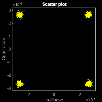
Create a thermal noise object with a noise temperature of 290 K and a sample rate of 5 MHz.
thNoise = comm.ThermalNoise('NoiseTemperature',290,'SampleRate',5e6);
Generate QPSK modulated data with an output power of 20 dBm.
data = randi([0 3],1000,1);
modData = (10^((20-30)/20)) * pskmod(data,4,pi/4);
Attenuate the signal by the free space path loss assuming a 1000 m link distance and a carrier frequency of 2 GHz.
d = 1000;                    % m
f = 2e9;                     % Hz
c = physconst('LightSpeed');                     % m/s
fsl = (4*pi*d*f/c)^2;
rxData = modData/sqrt(fsl);
Add thermal noise to the signal. Plot the noisy constellation.
noisyData = thNoise(rxData);
scatterplot(noisyData)
Create a thermal noise object with a 5 dB noise figure and a 10 MHz sample rate. Include 290 K antenna noise.
thermalNoise = comm.ThermalNoise('NoiseMethod','Noise figure', ...
    'NoiseFigure',5, ...
    'SampleRate',10e6, ...
    'Add290KAntennaNoise',true);
Generate QPSK modulated data with an output power of 1 W.
data = randi([0 15],1000,1);
modSig = qammod(data,16,'UnitAveragePower',true);
Attenuate the signal by the free space path loss assuming a 1 km link distance and a 5 GHz carrier frequency.
d = 1000;                   % m
f = 5e9;                    % Hz
c = physconst('LightSpeed');                    % m/s
fsl = (4*pi*d*f/c)^2;
rxSig = modSig/sqrt(fsl);
Add thermal noise to the signal and plot its constellation.
noisySig = thermalNoise(rxSig);
scatterplot(noisySig)
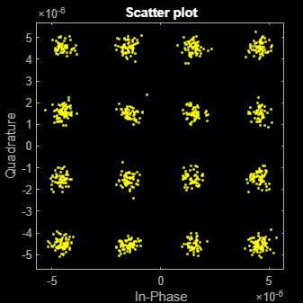
Estimate the SNR.
mer = comm.MER;
snrEst1 = mer(rxSig,noisySig)
snrEst1 =
22.6551
Decrease the noise figure to 0 dB and plot the resultant received signal. The signal is not completely noiseless because antenna noise is included.
thermalNoise.NoiseFigure = 0;
noisySig = thermalNoise(rxSig);
scatterplot(noisySig)
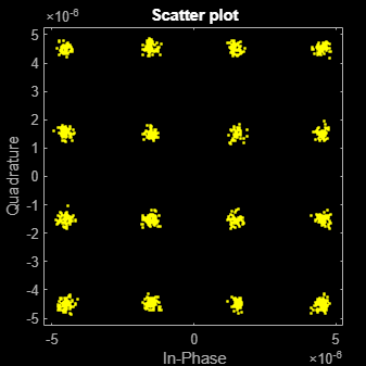
Estimate the SNR. The SNR is 5 dB higher than in the first case, which is expected given the 5 dB decrease in the noise figure.
snrEst2 = mer(rxSig,noisySig)
snrEst2 =
27.8598
snrEst2 - snrEst1
ans =
5.2047
Apply thermal noise to a multichannel signal and confirm that each channel has the same noise floor as returned by the info object function.
Create a comm.ThermalNoise object.
tn = comm.ThermalNoise
tn =
  comm.ThermalNoise with properties:

         NoiseMethod: 'Noise temperature'
    NoiseTemperature: 290
       ReferenceLoad: 1
          SampleRate: 1
Apply thermal noise to a multichannel signal and compute the signal variance for each channel.
x = tn(zeros(100000,3,'like',1i));
10*log10(var(x))
ans = 1×3
-203.9809 -203.9795 -203.9857
Use the info object function to return the receiver thermal noise floor.
info(tn)
ans = struct with fields:
    NoiseFloor: -203.9752
Use a GPU to significantly speed up communications system simulations when working with large data sets. To show the practical benefits and considerations of GPU acceleration in MATLAB®, the workflow compares simulation run times on both CPU and GPU platforms, helping users understand the practical benefits and considerations of GPU acceleration in MATLAB.
First, establish a baseline using the runTN helper function. The
function adds thermal noise to 2e6 symbols across multiple frames and
two spatial channels, simulating realistic channel conditions. It then benchmarks
execution time with timeit on an AMD EPYC 7262 8‑Core Processor
(CPU). The code uses a prototype variable to control the compute
target, wraps the simulation in a function handle, times the execution, and displays the
result.
Benchmark the simulation time on an AMD EPYC 7262 8‑Core Processor CPU.
prototype = 0;
f = @()runTN(prototype);
tCPU = timeit(f,1);
disp("Simulation time on a CPU: "+tCPU+"s")
Simulation time on a CPU: 0.19119s
Next, run the same benchmark on a GPU by converting prototype to
a gpuArray. The example uses an NVIDIA RTX A5000.
prototype = gpuArray(prototype);
f = @()runTN(prototype);
tGPU = gputimeit(f,1);
disp("Simulation time on a GPU: "+tGPU+"s")
Simulation time on a GPU: 0.0063784s
Finally, compute and display the speedup achieved with the GPU relative to the CPU.
disp("Simulation speedup on GPU vs CPU: "+tCPU/tGPU)Simulation speedup on GPU vs CPU: 29.9751
The simulation on a GPU is 29.97 times faster than a CPU.
Benchmark the run time of an end-to-end communications system simulation on both CPU
and GPU. Use the runSimulation helper function to process large data
batches end‑to‑end. Run the simulation on the CPU first, then on the GPU, and report the
run times and speedup.
Process the data on the CPU.
prototype = 0;
f = @()runSimulation(prototype);
tCPU = timeit(f,1);
disp("System simulation time on a CPU: "+tCPU+"s")
System simulation time on a CPU: 0.484s
Process the data on the GPU.
prototype = gpuArray(prototype);
f = @()runSimulation(prototype);
tGPU = gputimeit(f,1);
disp("System simulation time on a GPU: "+tGPU+"s")
System simulation time on a GPU: 0.068779s
Report the system level simulation speedup.
disp("System simulation speedup on GPU vs CPU: "+tCPU/tGPU)System simulation speedup on GPU vs CPU: 7.037
The simulation on a GPU is 7.03 times faster than a CPU.
Helper Functions
Use the runTN helper function to check the baseline of the CPU vs
GPU.
function rxSig = runTN(prototype)
    nf = 10;   % Noise figure
    sr = 10e6; % Sample rate
    tn = comm.ThermalNoise(NoiseMethod="Noise figure", NoiseFigure=nf, ...
        SampleRate=sr);
    for k=1:5
        txSig = randn(200e3, 2, like=cast(1i, like=prototype));
        rxSig = tn(txSig);
    end
end
Use the runSimulation helper function to benchmark the run time
of an end-to-end communications system simulation on both CPU and GPU.
function bitErr = runSimulation(prototype)
    M = 16;    % 16-QAM
    nf = 10;   % Noise figure
    sr = 10e6; % Sample rate
    tn = comm.ThermalNoise(NoiseMethod="Noise figure", NoiseFigure=nf, ...
        SampleRate=sr);
    ber = comm.ErrorRate();

    for k=1:5
        m = randi([0,1], log2(M)*200e3, 2, like=prototype);
        txSig = qammod(m, M, InputType="bit", UnitAveragePower=true);
        rxSig = tn(txSig);
        b = qamdemod(rxSig, M, OutputType="bit", UnitAveragePower=true);
        bitErr = ber(b(:), m(:));
    end
end
Algorithms
Wireless receiver performance is often expressed as a noise factor or figure. The noise factor, F, is defined as the ratio of the input signal-to-noise ratio, Si/Ni to the output signal-to-noise ratio, So/No, such that
Given the receiver gain G and receiver noise power Nckt, the noise factor can be expressed as
The IEEE® defines the noise factor assuming that noise temperature at the input is T0, where T0 = 290 K. The noise factor is then
k is Boltzmann's constant. B is the signal bandwidth. Tckt is the equivalent input noise temperature of the receiver and is expressed as
The overall noise temperature of an antenna and receiver Tsys is
where Tant is the antenna noise temperature.
The noise figure NF is the dB equivalent of the noise factor and can be expressed as
The noise power can be expressed as
where V is the noise voltage expressed as
and R is the reference load.