Compare Signal and Message Data Modes for Activity Diagrams
R2026bWhen you reference an activity diagram from a System Composer™ architecture, you can use the Data Mode property on the
input parameter node to model a continuous or event-driven simulation. You can use
signal mode for continuous execution from simulation start, or
message mode for event-driven execution that waits for discrete data.
This example shows the simulation behavior of each data mode using the same model. For
background on activity diagrams, see Describe System Behavior Using Activity Diagrams. For
information about input parameter nodes, see Implement Component Behavior Using Activity Diagrams.
This example uses the MessageVsSignal model. The component Generate Signal and Message has a Simulink behavior that generates the same data in form of signal and message with a delay of two seconds. The two output ports connect to different components with activity diagram behavior. One activity diagram expects signal data and the other expects message data. The activity diagrams perform a simple operation of adding 3 to the input value when a token arrives at the input parameter node.
open("MessageVsSignal.slx");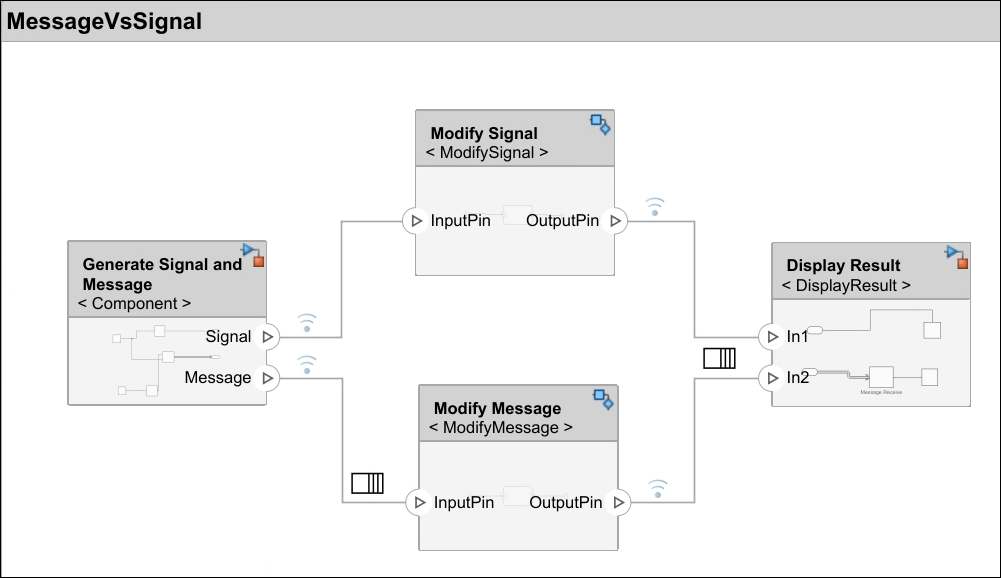
Signal Data Mode
In the signal path, the first component with Simulink behavior introduces a delay of
2 seconds before the signal reaches the activity diagram
component. Because a signal is continuous, the input parameter node on the activity
diagram receives a token at t = 0. The signal value is initially
zero, but the token is still present. The activity begins execution immediately at
simulation start. The output appears at t = 1 as the activity
received a token at t = 0 and the duration of the action node is set
to 1.

Message Data Mode
In the message path, the first component with Simulink behavior introduces the same
delay 2 seconds before the signal reaches the activity diagram
component. Unlike a signal, no message exists at the input parameter node until the
component sends one. The activity diagram is idle until the first message arrives after
the delay.

The activity diagram outputs a value only after the message arrives. The output is
delayed relative to the start of simulation because the activity did not receive a token
until the message arrived at t = 2.
Compare Behavior
Both paths have the same delay in the Simulink behavior component. The data mode setting on the input parameter node determines when the activity executes.
| Behavior | Signal Mode | Message Mode |
|---|---|---|
| Token at input parameter node | Present from t = 0 (signal is continuous, even
with value zero) | Absent until a message arrives after the delay |
| Activity start time | Begins at simulation start | Begins when the first message arrives |
| Output timing | Output appears immediately from t = 0 | Output appears only after the delay |
| Execution pattern | Single continuous execution throughout simulation | One execution per message received |
See Also
Functions
systemcomposer.createActivity|addNode|addParameter|getNode|getNodes|getFlow|connect|getParameter|getParameters|getPin|getPins|addPin|addTag|getParentPin|applyStereotype|removeStereotype|getStereotype|destroy|setBehaviorType|linkToModel
Objects
systemcomposer.activity.AcceptAction|systemcomposer.activity.Action|systemcomposer.activity.Activity|systemcomposer.activity.ActivityNode|systemcomposer.activity.ActivityFinal|systemcomposer.activity.ControlNode|systemcomposer.activity.Flow|systemcomposer.activity.FlowFinal|systemcomposer.activity.Model|systemcomposer.activity.JoinFork|systemcomposer.activity.Initial|systemcomposer.activity.MergeDecision|systemcomposer.activity.Parameter|systemcomposer.activity.Pin|systemcomposer.activity.SendAction|systemcomposer.activity.TimeAction
Tools
Blocks
- Initial Node | Action Node | Accept Action Node | Send Action Node | Pin | Parameter Node | Decision or Merge Node | Join or Fork Node | Flow Final Node | Time Action Node | Activity Final Node
Topics
- Describe System Behavior Using Activity Diagrams
- Establish Traceability and Extend Model Elements
- Simulate, Visualize, and Validate Activity Diagrams
- Compose Architectures Visually
- Implement Component Behavior Using Activity Diagrams
- Implement Component Behavior Using Stateflow Charts
- Implement Component Behavior Using Simscape

