Visualize PX4 Hardware-in-the-Loop (HITL) Simulation with VTOL UAV in Urban Environment
R2026bThis example shows how to visualize VTOL UAV Hardware-in-the-Loop (HITL) simulation within an urban environment by using Unreal Engine®.
Prerequisites
It is recommended to run two instances of MATLAB for this example. Use the first instance of MATLAB® deploy the controller model to Pixhawk® and run the HITL plant model. Use the second instance of MATLAB to set up and run the Unreal Engine visualization.
Set up and run the PX4 Hardware-in-the-Loop (HITL) Simulation with VTOL UAV example. This example will help you to understand the required hardware setup, as well as the HITL controller and plant models.
Set up and run the Visualize VTOL UAV Mission over Urban Environment example. This example shows how use to custom actor workflow in UAV Toolbox to visualize aircraft performance in a photorealistic environment.
Download and install UAV Toolbox Interface for Unreal Engine Projects. For more information about installing and setting up the UAV Toolbox Interface, see Install Support Package for Customizing Scenes.
This example uses a 3D Game Asset Urban Air Mobility Vehicle dataset, which contains a fbx file of a VTOL UAV and is approximately 6 MB in size. Download the
VTOLAssetZIP file from the MathWorks® website, then unzip the file.
zipFile = matlab.internal.examples.downloadSupportFile("uav","data/VTOLAsset.zip");
filepath = fileparts(zipFile);
dataFolder = fullfile(filepath,'VTOLAsset');
unzip(zipFile,dataFolder)
Getting Started in First Instance of MATLAB
To open the example livescript and directory which contains the Simulink project file, first run openExample('uav/VisualizeVTOLHITLFlightMissionOverUrbanEnvironmentExample') in the command window using the first MATLAB instance.
You must open the VTOLRefApp.prj project file to access the Simulink® model, supporting files, and project shortcuts that this example uses.
% Open the Simulink project
prj = openProject('VTOLApp');
To initialize the parameters and configurations of the HITL plant model, click the Initialize Plant Parameters shortcut or run the setupHITLConfiguration helper function.
setupHITLConfiguration;
To initialize the parameters and configurations of the HITL controller model, click the Initialize Controller Parameters shortcut or run the setupHITLController helper function.
setupHITLController;
Set Up HITL City Mission in First Instance of MATLAB
This example contains a sample mission in which the UAV takes off, performs guided flight, and lands in hover mode as defined in the setupHITLCityMission.m file.
Load the sample mission by clicking the HITL Unreal City Mission shortcut or by using the setupHITLCityMission helper function.
setupHITLCityMission;
Initialized city mission.
To create your own mission, you can customize the mission defined in the setupHITLCityMission.m file. The following table summarize different mission modes and the corresponding flight modes. Note that the modes are based on the format that the Path Manager uses.
Mission Mode | Action | Supported Flight Mode |
|---|---|---|
1 | Takeoff | Hover |
2 | Waypoint | Hover, Fixed Wing |
3 | Orbit | Hover, Fixed Wing |
4 | Land | Hover |
5 (Not used in this example) | RTL (Not used in this example) | N/A (Not used in this example) |
6 | Transition | Hover, Fixed Wing |
Deploy HITL Controller Model to Pixhawk Target in First Instance of MATLAB
The HITL_controller_top.slx file contains the HITL controller model. The model consists of the following subsystems:
VTOLAutopilotController— Reference flight controller design for a VTOL tilt-rotor UAV model.Actuator outputs— Parses theVTOLAutopilotControllersubsystem outputs into uORB messages.Estimator— Obtains VTOL UAV states from PX4 estimator for controller feedback.
Open the HITL_controller_top.slx model using the Open HITL Controller Model shortcut, or use the following code block.
controller_mdl = "HITL_Controller_top.slx";
open_system(controller_mdl)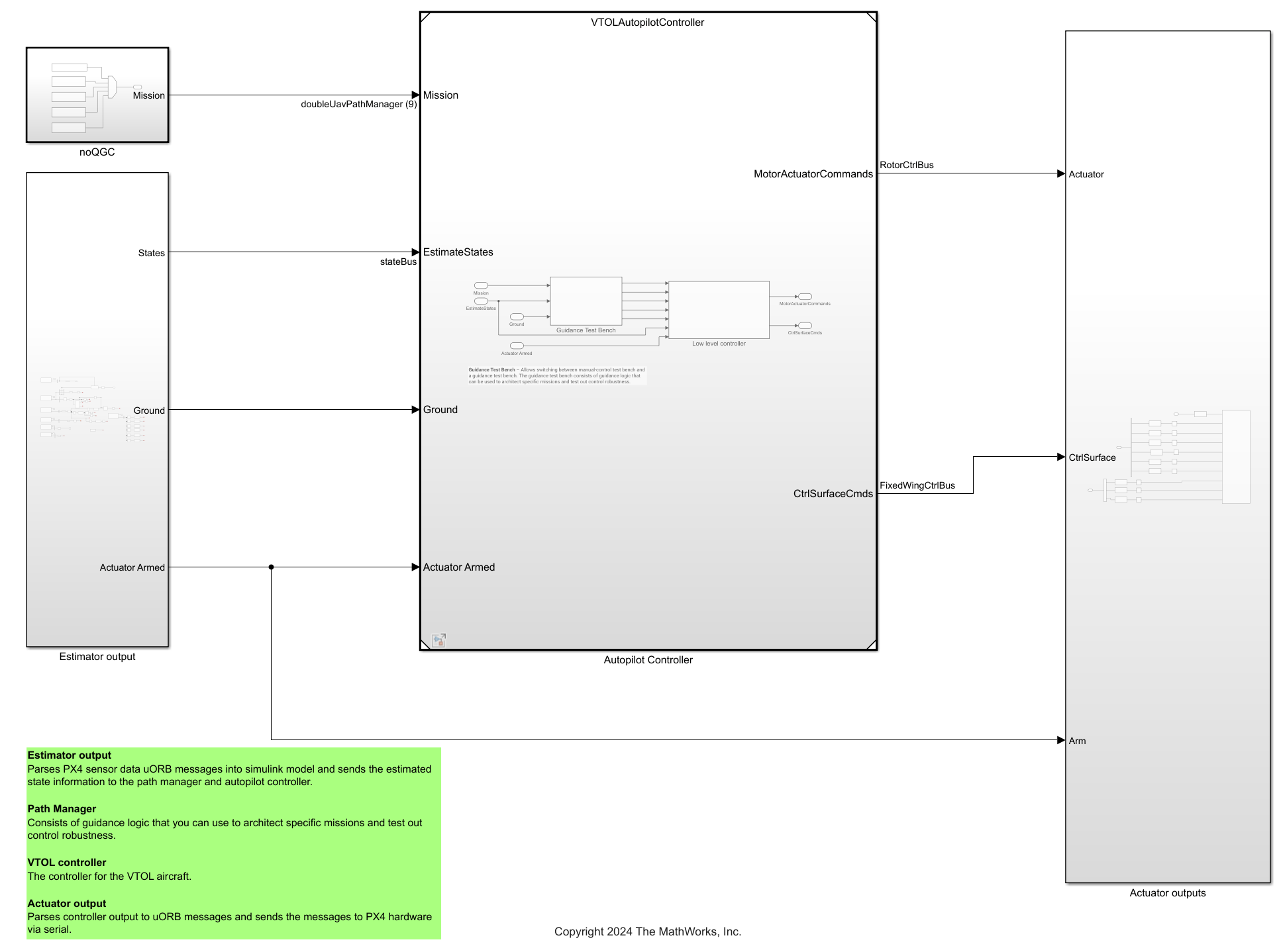
To generate the code of the flight controller model and deploy it to the Pixhawk board, select Build, Deploy & Start on the Hardware tab of the Simulink Toolstrip.

After completing deployment, the model launches QGroundControl.
Note :
If you are using Ubuntu, QGroundControl might not launch automatically. To launch QGroundControl, open the terminal and go to the folder where QGroundControl is downloaded and , and then enter this command:
./QGroundControl.AppImage.If you have changed the hardware, or are not using the pre-configured Simulink model, then you must configure your Simulink model as explained in Configure Simulink Model for Deployment in Hardware-in-the-Loop (HITL) Simulation. Run the following code block to launch the Configuration Parameters dialog box in a new window.
configObj = getActiveConfigSet('VTOLAutopilotController');
deploymentConfigSet = getRefConfigSet(configObj);
openDialog(deploymentConfigSet);
Configure Unreal Engine Visualization in Second Instance of MATLAB
Open Example and Project File
Launch the second instance of MATLAB to set up and run the Unreal Engine visualization. Open the example live script by running openExample('uav/VisualizeVTOLHITLFlightMissionOverUrbanEnvironmentExample'). Then, open the project file to access the Simulink model and supporting files.
% Open the Simulink project after running openExample('uav/VisualizeVTOLHITLFlightMissionOverUrbanEnvironmentExample')
prj = openProject('VTOLApp');
Point Model to Unreal Engine Project
Open the HITL_Unreal_Visualization.slx Simulink model.
open_system("HITL_Unreal_Visualization")
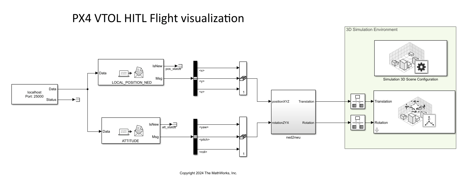
Open the Simulation 3D Scene Configuration block mask and set the Scene source parameter to Unreal Editor and supply the path to the AutoVrtlEnv Unreal Engine project on your system.
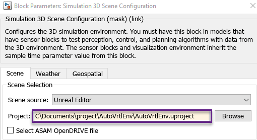
If you do not have the AutoVrtlEnv file, you must download the Install Support Package for Customizing Scenes support package to complete this step. The installation and setup process for the UAV Toolbox Interface for Unreal Engine Projects includes setting up the AutoVrtlEnv file.
Import VTOL UAV into Unreal Engine Scene
To launch Unreal Editor, open the Photorealistic subsystem. Then, open the Simulation 3D Scene Configuration block and click Open Unreal Editor
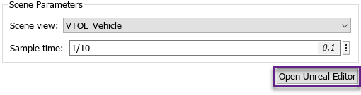
Click Add/Import in Unreal Editor and select New Folder from the context menu. Create a folder called EVTOL in the Content Browser pane, and then open the EVTOL folder.
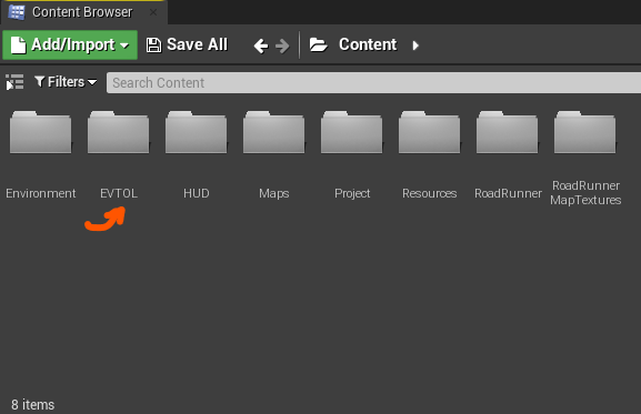
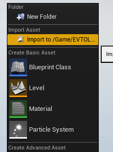
Click Add/Import again and then select Import to Game/EVTOL. Navigate to the folder that the VTOLAsset is saved in and select the VTOLAsset file to open the FBX Import Options dialog box.
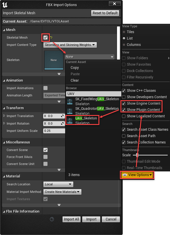
To select a skeleton mesh, you must first open the Skeleton drop down list and click the View Options drop down. Then, select both Show Engine Content and Show Plugin Content to add the UAV_Skeleton mesh option to the Skeleton drop down list. Finally, select UAV_Skeleton.
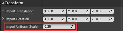
Set the Import Uniform Scale parameter to 0.25 in FBX Import Options to scale the VTOL asset to a smaller, more realistic size.
To finish the import of asset, click Import in Unreal Editor.
Customize VTOL UAV Asset
Double click VTOLAsset in the Content Browser pane to open the Asset Details window.
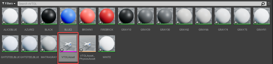
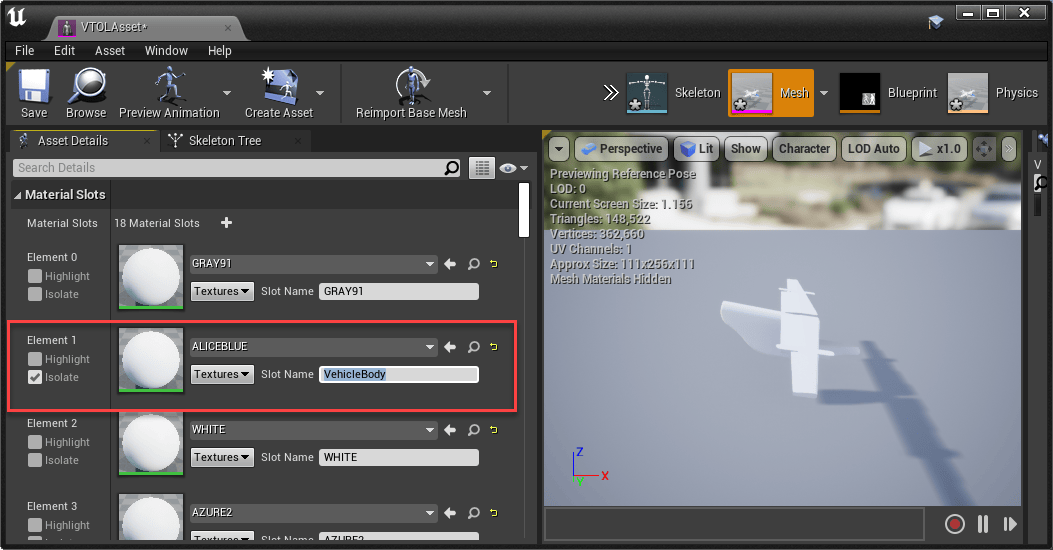
Select the element of the VTOL skeletal mesh that to be the main body of the vehicle and name it VehicleBody. For this VTOL asset, select Element 1, the fuselage, as the main body.
You can verify that Element 1 is the fuselage by selecting isolate to see which body the element is representing. Set the Slot Name of Element 1 to VehicleBody. Then, save the VTOL asset.
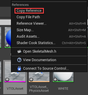
To copy the reference path to this asset, right-click the VTOLAsset skeletal mesh object in Content Browser pane and click Copy Reference.
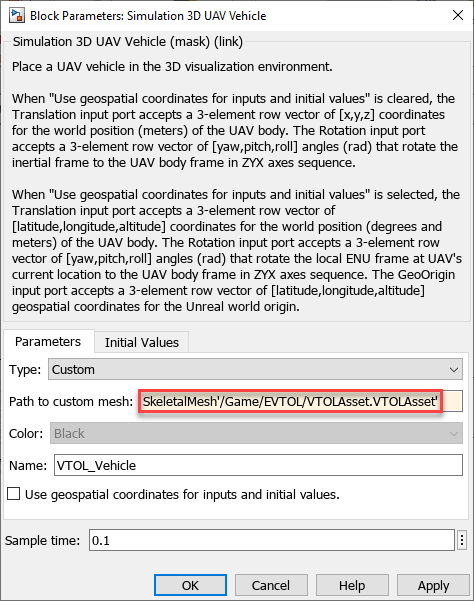
In the Simulation 3D UAV Vehicle block, set the Type parameter to Custom and then set the Path to custom mesh parameter to the reference path.
Load US City Block Scene
Navigate to Maps in Content Browser and click on USCityBlock to load the US City Block scene.

Run Unreal Engine Visualization in Second Instance of MATLAB
Run the HITL_Unreal_Visualization.slx model.
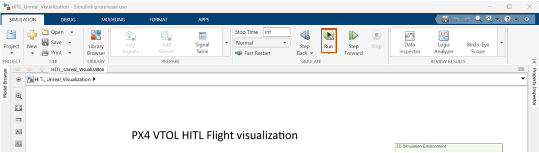
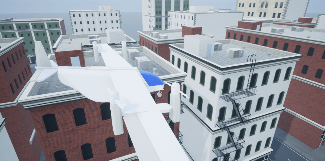
When the Simulink mode is initializing, click Play in Unreal Editor. Zoom out using mouse scroll to view the VTOL UAV. The VTOL UAV will remain stationary in the starting position until you run the HITL simulation in the next step.
Run HITL Simulation in First Instance of MATLAB
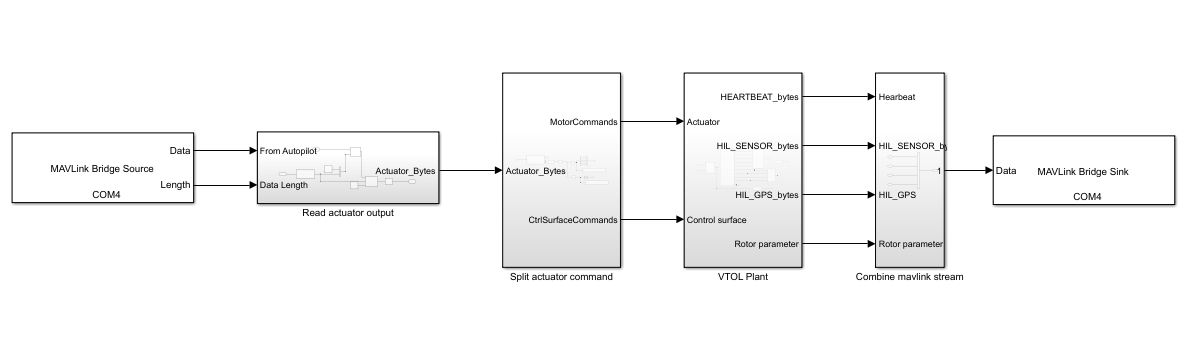
The HITL_Plant_top.slx file contains the HITL plant model. The model consists of the following blocks:
MAVLink Bridge Sourceblock — Reads the MAVLink messages from the Pixhawk board and sends it toVTOL PlantsubsystemVTOL Plantsubsystem — Plant model for the VTOL tilt rotor UAV, which simulates the aerodynamics, propulsion, ground contact, and sensors. The subsystem outputs sensor, rotor parameter, and GPS data.MAVLink Bridge Sinkblock — ParsesVTOL Plantsubsystem as MAVLink messages and sends the messages back to Pixhawk by using serial connection
Open the HITL_Plant_top.slx model by using the Open HITL Plant Model shortcut or by running the following code block in the first instance of MATLAB.
plant_mdl = "HITL_Plant_top.slx";
open_system(plant_mdl)
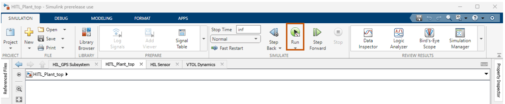
To start the HITL simulation, first run the HITL_Plant_top.slx.
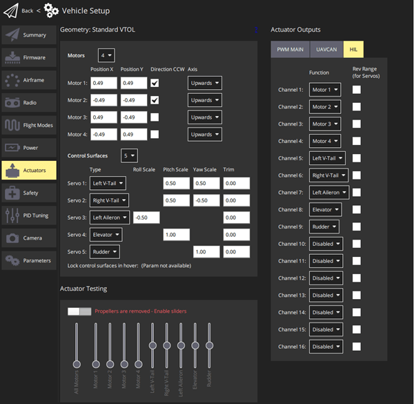
Then, Open QGroundControl and configure the actuators as shown. For more information, see Configure and Assign Actuators in QGroundControl.
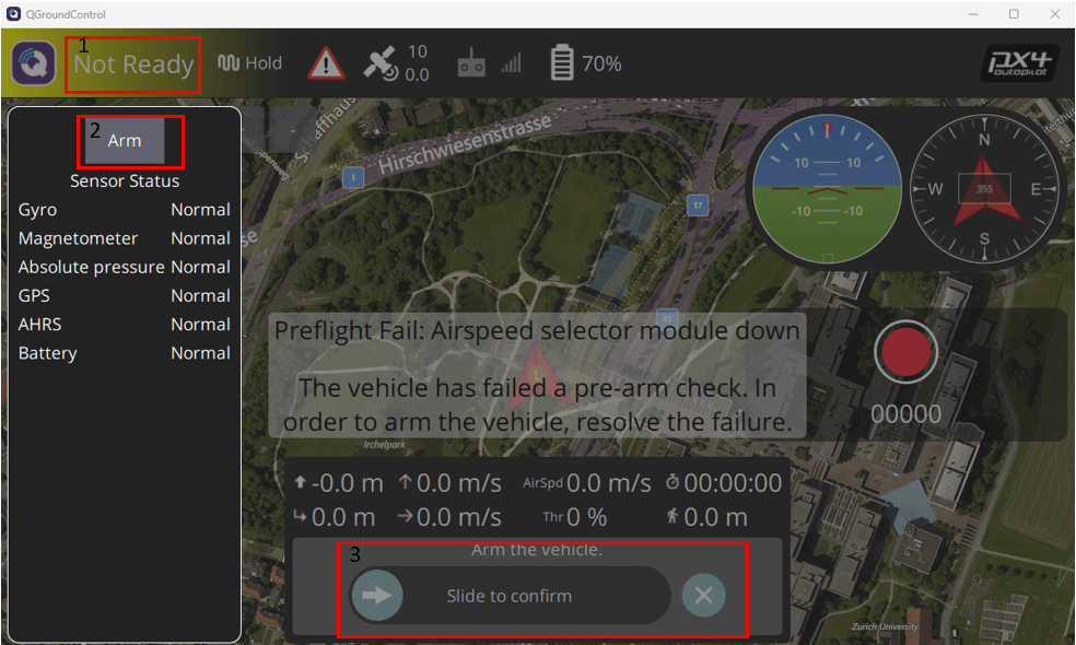
Next, select Fly View in QGroundControl. Arm the VTOL UAV to start the mission by selecting Arm.
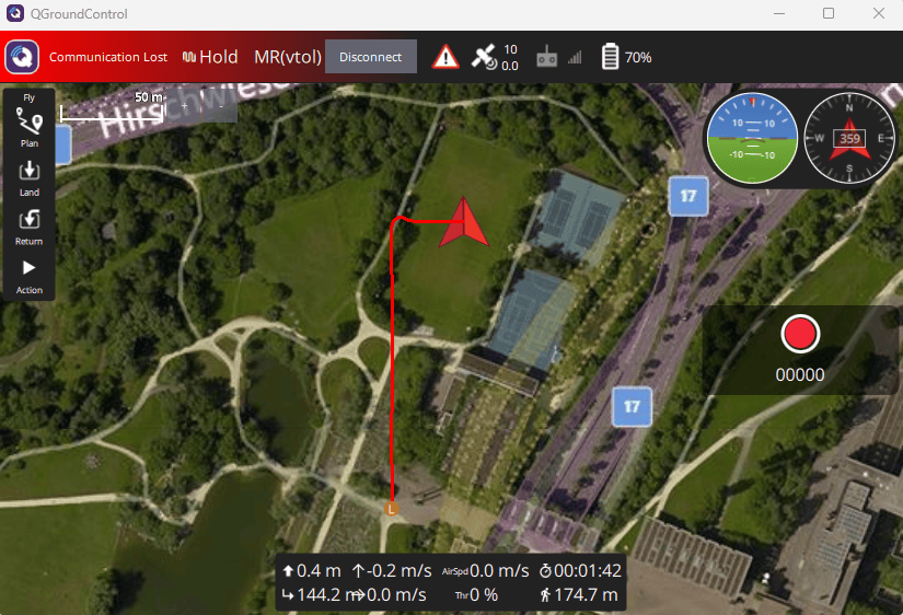
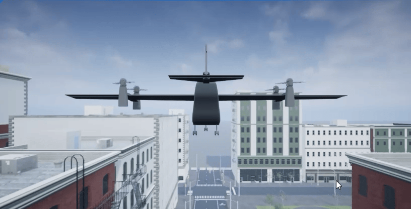
After the VTOL UAV is armed, the UAV takes off starts the mission, as shown in QgroundControl and the Unreal Engine visualization.
Before resuming to other examples in this example series, you must close the VTOLRefApp.prj Simulink project by running this command in the Command Window:
close(prj)
See Also
Design and Tune Controller for VTOL UAV | Simulation 3D Scene Configuration | Simulation 3D UAV Vehicle

