R2026b

New Features, Bug Fixes, Compatibility Considerations

View Consistent Sample Time Colors and Annotations Across Model Reference Hierarchies

Sample time colors, annotations, and the Timing Legend now remain consistent across a top model and its referenced models. The top model defines the timing context for the hierarchy. When you open a referenced model from the top model, it inherits sample time colors, annotations, and Timing Legend entries based on the top model's context. When opened as the top model, a referenced model uses its own independent timing context.

Toggling these overlays for any model in the hierarchy updates the visualization across the entire hierarchy, making it easier to inspect the timing behavior.

There are some limitations where this synchronization is not possible and referenced models use their own compiled timing information.

simulinkScreenshot function: Take a screenshot of a Simulink model or subsystem

Use the simulinkScreenshot function to take a screenshot of a Simulink® model or subsystem and display it in a figure window.

For example, this code loads the sf_car model and takes a screenshot of it.

load_system("sf_car");
simulinkScreenshot("sf_car");
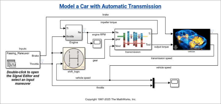
Screenshot of a model with the title "Model a Car with Automatic Transmission"

Simulink settings integrated into MATLAB settings

Behavior change

Starting in R2026b, Simulink settings are integrated into MATLAB® settings. Instead of appearing in a separate dialog box, Simulink settings are now located on panes in the MATLAB Settings dialog box.

You can still access Simulink settings from the Simulink Toolstrip. On the Modeling tab, select Environment > Simulink Settings. The MATLAB Settings dialog box opens to the Simulink pane, where you can specify general Simulink settings. To view editor or model file settings, in the navigation pane, expand Simulink and select Editor or Model File.

Using this command to open the Simulink settings is no longer supported.

slprivate('showprefs')

Instead, use this command to open the MATLAB Settings dialog box, and then select Simulink.

preferences
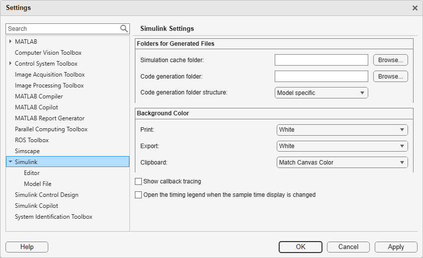
Simulink settings in the MATLAB Settings dialog box

Provide feedback on your experience in Simulink and Stateflow

Starting in R2026b, you can provide suggestions for improving Simulink and Stateflow® from the Simulink Editor. In the Simulink quick access bar located in the upper right corner of the editor, click the Feedback button.
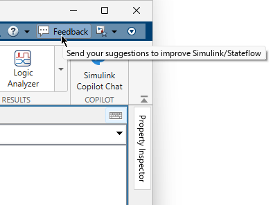
Feedback button in the Simulink quick access toolbar with this tooltip: "Send your suggestions to improve Simulink/Stateflow"

Use Quick Mode in Finder to search model elements without loading references and libraries

Use Quick Mode in the Finder to search for model elements of the current system without loading referenced models or libraries. By searching without loading references, Quick Mode reduces search time for large model hierarchies.

In Quick Mode, the Finder displays matches from unloaded references as grayed-out results. Double-click a result to load references and view additional matches. Starting in R2026b, Quick Mode is the default search mode in Finder.

For more information, see Search Using Quick Mode.
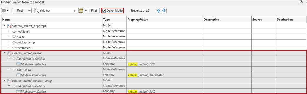
unloaded-references

 Functionality being removed or changed

Blocks have a minimum size of 5-by-5 pixels

Behavior change

All blocks in a model must have a size of at least 5-by-5 pixels. Simulink adjusts block coordinates so that the width and height are at least 5 pixels in these situations:

  • The coordinates you specify for the Position parameter result in a width or height smaller than 5 pixels.

  • You open or load a model created in a previous release that contains one or more blocks with smaller dimensions.

For more information, see Programmatically Specify Block Parameters and Properties and add_block.

Simulation Analysis and Performance

 Organize signal visualizations using tabs in the Simulation Data Inspector

You can now organize your visualizations in the Simulation Data Inspector using up to eight independent tabs, each with its own subplot layout and settings. You can:

  • Add tabs with the New Tab button .

  • Reorder tabs by dragging.

  • Rename, close, or change tab color by right-clicking.

To manage tabs programmatically, use the Simulink.sdi.TabGroup object. This object is a container for Simulink.sdi.Tab objects, each representing an open tab in the Simulation Data Inspector. To create, access, and manage tabs, use these functions with the Simulink.sdi.TabGroup object:

To manage individual tabs, use these functions with the Simulink.sdi.Tab object corresponding to the tab of interest:

 Analyze Simulink Profiler and Solver Profiler results using AI

To simplify and speed up performance analysis, generate AI explanations of profiling results from the Simulink Profiler and Solver Profiler.

  • The Simulink Profiler AI explanation summarizes key findings and identifies potential bottlenecks in the simulation.

  • The Solver Profiler AI explanation summarizes key findings, identifies potential bottlenecks, and provides actionable recommendations to improve simulation performance.

To generate AI explanations of profiling results, you must have a Simulink Copilot license.

Techniques to Speed Up Simulink Simulations: Self-paced, interactive course available as part of Online Training Suite subscription

Techniques to Speed Up Simulink Simulations is a new course that teaches you to:

  • Analyze models for configuration parameter settings that impact simulation performance using the Performance Advisor.

  • Analyze solver behavior that impacts simulation performance using the Solver Profiler.

  • Identify blocks and subsystems that contribute most to the overall compilation and execution time using the Simulink Profiler.

  • Choose appropriate simulation modes to accelerate the simulation of model reference hierarchies.

  • Avoid recompilation in batch and iterative simulations by using fast restart.

For more information, see Techniques to Speed Up Simulink Simulations.
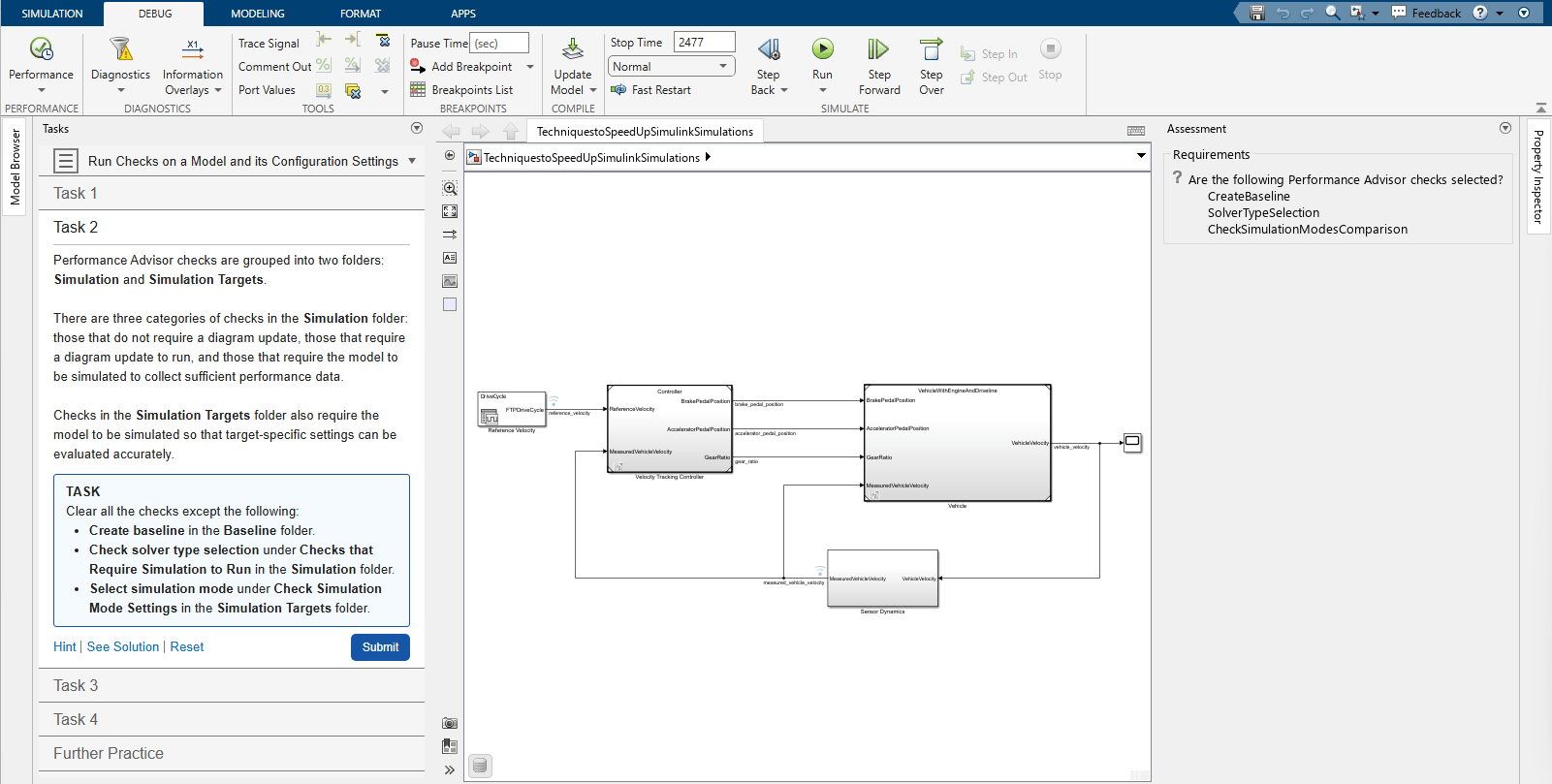
Interactive task in Techniques to Speed Up Simulink Simulations

Plugin Solvers: Write custom fixed- or variable-step explicit and implicit solvers for Simulink simulations

To write custom solvers for Simulink simulations, use the Simulink.Solver.FixedStepSolver and Simulink.Solver.VariableStepSolver base classes. During simulation, the solver integrates continuous states and advances time. Using the plugin solver interface, you can write custom integration algorithms to solve systems of ordinary differential equations (ODEs) and differential-algebraic equations (DAEs). To implement a plugin solver, you define the integration algorithm in the step method of the solver class. The Simulink simulation environment provides solver services, such as zero-crossing detection.

Plugin solvers do not support:

  • Rapid accelerator simulation

  • Software-in-the-loop (SIL) and processor-in-the-loop (PIL) simulation

  • Deployment with Simulink Compiler™

  • Production code generation using Simulink Coder™ or Embedded Coder®

Local Solver Analyzer: Configure and profile local solvers in model hierarchies

Using the new Local Solver Analyzer, you can:

  • Visualize a model reference hierarchy.

  • Enable, disable, and configure local solvers in referenced models.

  • Profile one or more local solvers in the model hierarchy.

To open the Local Solver Analyzer, open the Solver Profiler. Then, in the toolstrip, in the Analyze section, click Local Solver.

When you profile local solvers, the Local Solver Analyzer displays a summary of the profiling results. To analyze the profiling results, view the profiling data in the Local Solver Profiler. The Local Solver Profiler provides the same data and visualizations as the Solver Profiler but does not support running profiling simulations. To profile a local solver, you must simulate the top model.

Speed up simulations by solving algebraic loops as differential-algebraic equations

You can now solve algebraic loops as differential-algebraic equations (DAEs). In some cases, solving an algebraic loop as a system of DAEs can significantly speed up simulations because solving the loop does not invoke the algebraic loop solver.

To specify how the software solves an algebraic loop, use the new Equation format parameter of the Algebraic Constraint block. To solve the loop as a DAE, set Equation format to Differential Algebraic Equation.

For information about when to solve algebraic loops as DAEs, see Algebraic Constraint.

Set breakpoints on outputs of virtual subsystems while stepping block by block

While debugging a simulation block by block, you can now add breakpoints to the outputs of virtual subsystems, including masked subsystems and custom blocks implemented as masked subsystems. The simulation pauses when the output of the nonvirtual source block for the port satisfies the breakpoint condition.

When the simulation pauses on one of these breakpoints:

  • The virtual subsystem is highlighted green in the block diagram.

  • The Breakpoints List highlights the row for the breakpoint.

  • The status bar shows the path to the virtual subsystem.

If multiple breakpoints on virtual subsystem outputs share the same source block, all associated subsystems are highlighted in the block diagram. The Breakpoints List highlights the rows for all the breakpoints.

In previous releases, you could add breakpoints on the outputs of virtual subsystems, but the breakpoints did not pause the simulation and appeared as invalid in the block diagram. To pause the simulation based on the signal value, you had to add a breakpoint on the nonvirtual source block that produces the output.

Import data from Parquet files into the Simulation Data Inspector

You can now import simulation data from Parquet files into the Simulation Data Inspector, complementing the Parquet export capability introduced in R2026a. This new import capability includes selective signal loading to bring in only the data you need for comparison and analysis. You can import scalar and multidimensional signals with real and complex data of any built-in data type, as well as enumerations, strings, fixed-point data, buses, and arrays of buses.

When a JSON sidecar file exists in the same directory as the Parquet file, the Simulation Data Inspector automatically detects it and applies the signal metadata and multi-run information from the sidecar.

To inspect the contents of a Parquet file before importing, use these new functions:

For more information, see Parquet File Format for Simulation Data.

Stream data in the Simulation Data Inspector when logging last n signal values

The Simulation Data Inspector now streams data during simulation when you log only the last n signal values using the Limit data points to last parameter. Before R2026b, when you configured logging to capture only the last n signal values, the Simulation Data Inspector did not stream data during simulation.

Export simulation data to CSV files from the Simulation Data Inspector

You can now export logged simulation data from the Simulation Data Inspector to CSV files. You can export data using shared or individual time columns. You can also include metadata such as units, data types, block paths, interpolation method, and port index. You can export data of any built-in numeric type, as well as enumerations, fixed-point data, complex signals, buses, and multidimensional signals. For more information, see Export Data to CSV File.

Import additional data types and metadata from CSV files into the Simulation Data Inspector

The Simulation Data Inspector now provides expanded CSV import capabilities. You can import CSV files that contain richer signal metadata, multiple runs, and additional data types. The expanded import matches the R2026b CSV export, so you can export and reimport simulation data using CSV files.

For more information, see CSV File Format for Simulation Data.

Export simulation data to value change dump (VCD) files for HDL verification

You can now export simulation data from the Simulation Data Inspector to VCD format. VCD files are compatible with HDL verification tools such as ModelSim, Questa, and GTKWave, enabling you to compare Simulink behavioral models with HDL simulations. For more information, see Export Data to VCD File.

Export time-varying parameters to Excel files from the Simulation Data Inspector

You can now export parameter data that changes over time from the Simulation Data Inspector to Microsoft® Excel® files.

Specify component when unpacking targets from Simulink cache file

You can now unpack component and subcomponent artifacts from the Simulink cache file for a software component model configured for SOA application deployment by specifying a Component name-value argument when using the slxcunpack function.

 Functionality being removed or changed

Record logged workspace data in Simulation Data Inspector parameter will be removed

Still runs

The Record logged workspace data in Simulation Data Inspector configuration parameter will be removed in a future release. This parameter sends data logged in a format other than Dataset and data logged using the To File block to the Simulation Data Inspector when a simulation pauses or stops. After removal, this data will no longer be sent to the Simulation Data Inspector. This change will not affect data logged using the Dataset format.

Component-Based Modeling

 Reference published models for faster simulation

To speed up simulation, you can now reference published models. These ready-to-run versions of Simulink models contain build artifacts that Simulink unpacks and uses as needed. Simulink skips rebuild checks for published models, reducing model compilation and build overhead.

With published models, you can:

  • Log signals that the author configured for logging.

  • Tune parameters.

  • Unpack the original data sources, such as data dictionaries.

  • Provide an alternate value source for external parameters.

  • Unpack supplemental files included by the author, such as instructions, test results, and code coverage reports.

For more information, see Reference Published Models.

While using a published model typically requires only a Simulink license, creating a published model requires a Simulink Coder license. For more information, see Publish Models to Speed Up Simulation and Code Generation (Simulink Coder).

 Software Component Designer: Design, simulate, and deploy software components for service-oriented architecture applications

In R2026b, the Software Component Designer for Simulink support package provides a model-based workflow for designing software components for service-oriented architectures (SOA). You can develop, validate, and deploy software components independently before integrating them into larger systems. Using the Software Component Designer app, you can configure a Simulink model as a software component model, define data and service interfaces, configure quality of service (QoS) properties, and validate component behaviors using test harnesses.

Key capabilities of the Software Component Designer app include:

  • Define software components — Configure a Simulink model as a software component model and define data and service interfaces using the Interface Editor.

  • Configure QoS properties — Configure communication and execution properties on port elements to model send-receive and client-server communication patterns at the component level.

  • Component-level testing — Validate component behaviors before integration into compositions by generating test harnesses for software component models (requires Simulink Test™ and System Composer™).

  • Code generation and deployment — Generate fully deployable applications for Linux® platforms from software component models, including service implementation and middleware bindings for DDS and SOME/IP (requires Embedded Coder).

For more information, see Software Component Models in Simulink.

For an example, see Model and Simulate Services of Brake Control System.

In R2026b, the Simulink Variant Manager™ product replaces the Variant Manager for Simulink support package.

The Simulink Variant Manager user interface, command-line API, and workflows remain the same as in the Variant Manager for Simulink support package. Existing models and scripts continue to work without changes.

For more information, see Simulink Variant Manager (Simulink Variant Manager).

Rename elements of ports programmatically

To rename elements of bus element ports at subsystem and model interfaces, you can use the new renameElementOfPort function. For more information and examples, see renameElementOfPort.

Use improved programmatic name for model configuration parameter

The model configuration parameter ModelReferencePassRootInputsByReference (Pass fixed-size scalar root inputs by value for code generation) now has the programmatic name ModelReferencePassRootInputsByValue. The name better matches the dialog box name and the programmatic settings of the new name match the settings of the dialog box.

There are no plans to remove support for references to the existing programmatic name. Its settings remain the same.

Faster model update for Multiversion Co-Simulation components

Starting in R2026b, Multiversion Co-Simulation components update faster when you rebuild models without structural changes. Simulink reuses cached artifacts to avoid redundant computations during model update.

Use blocks with enable methods inside variant choices of run-time Variant Subsystem block

You can now use blocks with enable methods inside the variant choices of a Variant Subsystem block with the Variant activation time parameter set to runtime. An enable method is called just before a block starts executing. Examples of blocks with enable methods include:

  • Stateflow charts

  • Enabled Subsystem blocks

  • Function-Call Subsystem blocks

  • Triggered Subsystem blocks

For more information on run-time variants, see Control Active Choice of Variant Subsystem During Simulation or Execution of Generated Code.

Add bus element blocks as interface ports on Variant Subsystem and Variant Assembly Subsystem blocks

Starting in R2026b, you can use In Bus Element and Out Bus Element blocks as input and output ports on Variant Subsystem or Variant Assembly Subsystem blocks, alongside existing port types Inport, Outport, Connection Port (Simscape), and control ports Enable, Trigger, and Reset.

For example, consider a Variant Subsystem block Controller. The first input port of the Controller block is an In Bus Element block named sensorInputs that groups related signals speed, position, and temperature. The second input port is also an In Bus Element block named operationMode that groups related signals type and status. The Controller block has two variant choices, Linear Controller and Nonlinear Controller. Each variant choice contains corresponding input ports for sensorInputs and operationMode.

When you simulate the model, Simulink maps the In Bus Element blocks between Controller and its variant choices by matching the port names sensorInputs and operationMode so that the correct signals route to each variant choice.

Variant Subsystem block Controller with In Bus Element ports, containing two variant choices

When using bus element ports in a Variant Subsystem or Variant Assembly Subsystem block, these restrictions apply:

  • Bus element block port names at the Variant Subsystem interface must be unique.

  • Routing individual bus elements to each variant choice is not supported. In Bus Element and Out Bus Element blocks must specify the bus port.

  • Unlike Outport blocks, the Specify output when source is unconnected and Output function call parameters are not available for Out Bus Element blocks in a Variant Subsystem block.

Suppress variant choice diagnostics for inactive child Variant Subsystem blocks when parent is inactive

In a child Variant Subsystem block, when neither the Built-in empty choice nor the Built-in passthrough choice parameter is selected, the block requires at least one active variant choice during simulation.

Starting in R2026b, for child Variant Subsystem blocks where neither parameter is selected, Simulink evaluates the variant control expressions of the parent block and the child Variant Subsystem block before reporting a diagnostic. If the child Variant Subsystem block is inactive because its parent block is inactive, Simulink suppresses the diagnostic, as the inactive state is inherited and does not require resolution. Diagnostics are reported only when the variant control expressions of the parent and child blocks indicate a configuration that requires action. For example, when the variant control expressions do not overlap and the child Variant Subsystem block can never become active under any parent condition.

Previously, Simulink reported a diagnostic for every inactive child Variant Subsystem block that had no active variant choice, regardless of whether the parent block was also inactive. This behavior produced diagnostics in cases where the child block inherited its inactive state from the parent block and no resolution was needed.

The table demonstrates how the relationship between variant control expressions of the parent block and child Variant Subsystem block determines whether diagnostics for inactive child blocks are reported or suppressed.

RelationshipParent Variant Control ExpressionChild Variant Control ExpressionDiagnostic Behavior
Variant control expressions of child block are equal to those of the active variant choice of the parent.

V == 1 || V == 2

V == 1 || V == 2

Diagnostic is suppressed.
Variant control expressions of child block are mutually exclusive from those of the active variant choice of the parent.

V == 1 || V == 2

V == 3 || V == 4

Diagnostic is reported.
Variant control expressions of child block are a subset of the active variant choice of the parent.

V == 1 || V == 2

V == 2

Diagnostic is reported only when the variant choice of the parent is active.
Variant control expressions of child block are a superset of those of the active variant choice of the parent.

V == 1

V == 1 || V == 2

Diagnostic is suppressed.

Consider the Nonlinear Controller block, which is a variant choice within the Variant Subsystem block Controller, and which has a variant control expression V == 2 || V == 3. Inside this block, there is a child Variant Subsystem block saturationLogic with the variant control expression V == 2 || V == 4.

  • If you set the variant control variable V to 1, both the parent Nonlinear Controller block and child saturationLogic block are inactive. Simulink suppresses diagnostics for the child block because its inactivity is inherited from the inactive parent.

  • If you set V to 2, both the parent and child blocks are active. No diagnostic is reported.

  • If you set V to 3, the parent block Nonlinear Controller is active. The child block saturationLogic remains inactive since V == 3 does not satisfy the variant control expression of the child block. Simulink reports a diagnostic for the child block because it is expected to be active when the parent is active, but no valid variant choice is selected.

Variant Subsystem block Controller with Nonlinear Controller as a variant choice containing child Variant Subsystem block saturationLogic

Simulate Variant Subsystem blocks with activation time set to update diagram analyze all choices as virtual subsystems

Starting in R2026b, Simulink treats Variant Subsystem blocks with the Variant activation time parameter set to update diagram analyze all choices as virtual subsystems. With this change, Simulink detects delays in feedback loops that contain these blocks and reports only true algebraic loops.

In previous releases, these blocks were treated as nonvirtual subsystems, which could lead to the detection of artificial algebraic loops in feedback loops and prevent these optimizations.

Variant Subsystem blocks with code compile, startup, or runtime activation times remain atomic, as these activation times determine the active variant choice after the update diagram time and the active variant choice may change in a later phase.

For more information, see Virtual and Atomic Behavior of Variant Subsystem Blocks for Different Activation Times.

Use Simulink.DataStore object to define data stores

Starting in R2026b, you can use the Simulink.DataStore object to define data stores with support for data store references, diagnostic checks, and sharing across model references. This object makes it easier to manage and access large numbers of data stores in a model.

Previously, you could use Simulink.Signal object to define data stores. However, the Simulink.Signal objects do not provide Data Store Memory block capabilities such as Data store reference, Share across model instances and Diagnostics.

Change the active choice of variant parameters and variant parameter banks during simulation or execution of generated code

You can now change the active choice of variant parameters (Simulink.VariantVariable objects) and variant parameter banks (Simulink.VariantBank objects) during simulation or execution of the generated code. To enable run-time activation, set the ActivationTime property in the associated Simulink.VariantControl object to 'runtime'. Then, switch the active variant by modifying the value of the variant control variable.

To write to the variant control variable, you can use either of these options:

  • Place a Parameter Writer block inside a conditionally executed subsystem or in an event function. Each time the Parameter Writer block writes to the variant control variable, the generated code calls a separate method that switches the active variant parameter value or the active pointer variable used by the variant parameter bank.

  • Use the setVariable function of a Simulation object (while simulation is paused). The generated code that switches the active variant appears in the model step or model output function (depending on the code structure) before the variant is used.

Use symbolic dimensions in variant parameters for AUTOSAR code generation

Starting in R2026b, you can use symbolic dimensions to specify array sizes for variant parameters (Simulink.VariantVariable) in models configured for AUTOSAR code generation. In the generated C code, the code generator uses the symbolic dimension as a system constant to size the variant parameter arrays.

To define a symbolic dimension, add a system constant in the Architecture Data section of a Simulink data dictionary linked to the AUTOSAR component. Set the Specification property of the variant parameter to an AUTOSAR.Parameter object, and set the dimensions of this object to reference the system constant name. Define the variant control as a Simulink.VariantControl object. Set the value of the object to an AUTOSAR.Parameter object mapped to a system constant, and set the activation time to code compile. Code generation exports the symbolic dimension and the variant control as system constants and the variant choices as variation point proxy entries in the generated ARXML. For more information, see Configure Variant Parameter Values for AUTOSAR Elements (AUTOSAR Blockset).

In this example, the model uses a variant parameter K, defined as a Simulink.VariantVariable with two choices. The conditions for the choices are defined as Simulink.VariantExpression objects VExpr_Cond1 and VExpr_Cond2, which represent the variant control expressions V == 1 and V == 2, respectively. The Specification property of K is set to an AUTOSAR.Parameter object KSpec with its dimensions set to [1,P], where P is a system constant from the architecture data that specifies the symbolic dimension.

Model shows a Gain block that uses variant parameter K to scale the input signal

The model defines the variant parameter K and its associated objects in the Design Data section of a Simulink data dictionary. The data dictionary defines the system constant P in the Architecture Data section. For more information on defining system constants in the Architecture Data section, see Manage AUTOSAR Architectural Data With Data Dictionaries (AUTOSAR Blockset).
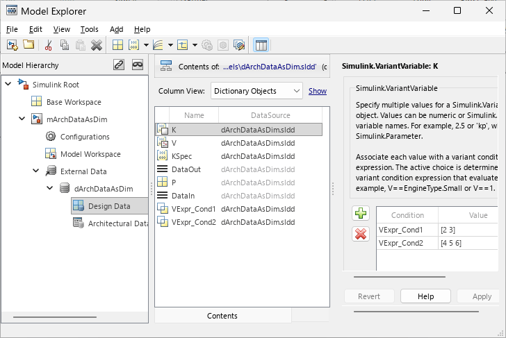
Model Explorer shows variant parameter K with choices for conditions VExpr_Cond1 and VExpr_Cond2

When you generate code for this model, the stub file Rte_Cfg.h defines the system constants for the symbolic dimension P, the variant control V, and the variation points.

/* File: Rte_Cfg.h */

/* Variation points */
#define Rte_SysCon_VExpr_Cond1         (V == 1)
#define Rte_SysCon_VExpr_Cond2         (V == 2)

#define P                              3
#define Rte_SysCon_P                   P
#define V                              2
#define Rte_SysCon_V                   V

The header file mArchDataAsDim.h uses the system constant Rte_SysCon_P as the symbolic dimension for the variant parameter array K. The #if preprocessor conditionals guard the variant parameter definition based on the variant control.

/* File: mArchDataAsDim.h */

/* PublicStructure Variables for Internal Data, for system '<Root>' */
typedef struct {
  float64 Output1[Rte_SysCon_P];       /* '<Root>/Gain2' */
} ARID_DEF_mArchDataAsDim_T;

/* Parameters (default storage) */
struct P_mArchDataAsDim_T_ {

#if Rte_SysCon_VExpr_Cond1 || Rte_SysCon_VExpr_Cond2

  sint16 K[Rte_SysCon_P];              /* Variable: K
                                        * Referenced by: '<Root>/Gain2'
                                        */
#endif
};

The source file mArchDataAsDim.c assigns the values for each choice of the variant parameter. The code conditionally compiles the values based on the variant control V.

/* File: mArchDataAsDim.c */

/* Block parameters (default storage) */
P_mArchDataAsDim_T mArchDataAsDim_P = {

#if Rte_SysCon_VExpr_Cond1 || Rte_SysCon_VExpr_Cond2

  /* Variable: K
   * Referenced by: '<Root>/Gain2'
   */
#if Rte_SysCon_VExpr_Cond1

  { 2, 3 }
#elif Rte_SysCon_VExpr_Cond2
  { 4, 5, 6 }
#endif
#endif
};
The step function uses the symbolic dimension Rte_SysCon_P to iterate over the variant parameter array.
/* File: mArchDataAsDim.c */

/* Model step function */
void mArchDataAsDim_Step(void)
{
  ...
  for (i = 0; i < Rte_SysCon_P; i++) {
    mArchDataAsDim_ARID_DEF.Output1[i] = (float64)mArchDataAsDim_P.K[i] *
      tmpIRead[i];
  }
  ...
}

Run SIL and PIL simulations for models with variant parameter banks

Starting in R2026b, you can run software-in-the-loop (SIL) and processor-in-the-loop (PIL) simulations on models that use variant parameter banks (Simulink.VariantBank objects) to group variant parameters. Previously, SIL and PIL simulations were not supported for models with variant parameter banks.

This capability is supported only for variant parameter banks defined in the base workspace or in a Simulink data dictionary. You can set the top model or a Model block to SIL or PIL simulation mode when variant parameter banks are used in a single model or shared across a model reference hierarchy. You can also use test harnesses to verify models with variant parameter banks in SIL or PIL mode and to run fast restart simulations to test different variant choices without rebuilding the generated code.

For more information, see Simulink.VariantBank and SIL and PIL Simulations (Embedded Coder).

Generate code with inlined default parameter behavior for variant parameters initialized by a Parameter Writer block

Starting in R2026b, you can generate code for models where a Parameter Writer block writes to a Simulink.VariantControl object used by variant parameters (Simulink.VariantVariable objects) when you set the Default parameter behavior model configuration parameter to Inlined. Previously, generating code for this workflow produced an error that required you to set Default parameter behavior to Tunable.

To use this workflow, the Simulink.VariantControl object must meet these conditions:

  • The ActivationTime property is set to startup.

  • The object is defined in the base workspace, data dictionary, or model workspace and is not configured as a model argument.

  • For variant controls defined in the base workspace or a data dictionary, the storage class must produce a tunable variable in the generated code. For variant controls defined in the model workspace, only Auto and Model Default storage classes are supported.

This workflow also supports models that use variant parameter banks (Simulink.VariantBank objects) to group variant parameters.

For more information, see Initialize Variant Control Value of Variant Parameter Using Parameter Writer Block.

Generate reusable subsystem reference code in custom folders

Starting in R2026b, you can generate and reuse subsystem reference code without requiring the subsystem file and top model to share the same folder. You can now:

  • Specify a custom location to generate subsystem reference code.

  • Generate code even when the subsystem file is in a different folder from the top model.

  • Independently use model-specific or target-specific folder structures to generate codes for subsystem reference and top model.

Before R2026b, you had to keep the subsystem file and the top model in the same folder and generate code in that folder using a target-specific folder structure. The top model also had to use a target-specific structure to reuse the subsystem code.

To generate reusable code from a Subsystem Reference block, mark its test harnesses as unit tests. For more information, see Define Interfaces and Verify Component Use in Validate Subsystem Reference Use in Model and Generate Reusable Code.

To set a specific code generation folder for the subsystem file slexReusableSS, specify an absolute or relative path by using the new Simulink.SubsystemReference.setCodegenPath function:

Simulink.SubsystemReference.setCodegenPath("slexReusableSS","/modelgencode");

If the specified folder does not exist, Simulink creates the folder. You can also use the code generation folder setting defined in your project or set a global code generation folder by setting the CodeGenFolder parameter.

Simulink.fileGenControl("set","CodeGenFolder","/project/modelgencode");

If you do not specify a path, Simulink generates the code in the folder that contains the subsystem file.

To reuse the code, the top model reads the code from the location where it was generated. To set the location where the top model generates the code, set the CodeGenFolder parameter. If you do not specify a path, Simulink generates the code in the current working directory.

Support for Simulink.VariantControl and Simulink.VariantVariable objects in mask initialization code for tunable code generation

Starting in R2026b, you can define Simulink.VariantControl and Simulink.VariantVariable objects (variant parameters) directly in the mask initialization code of a masked block. Create a mask on a Variant Subsystem and define mask dialog parameters that control variant behavior. Then use these values in the mask initialization code to create variant controls and variant parameters to specify the active variant choices and variant parameter values for child blocks in the masked subsystem.

When you create variant objects by using supported mask initialization code and set the variant control activation time to startup, the generated code preserves variant expressions for tunability and initializes variant parameter values in the model initialization function. This workflow does not support code compile variant activation time. For more information, see Preserve Variant Parameter Expressions from Mask Initialization in Generated Code (Simulink Coder).

 Functionality being removed or changed

Code generator applies initial value set for signal objects configured with Auto storage class

Behavior change

Starting in R2026b, if you use Simulink Coder or Embedded Coder to generate code, when a signal object is configured with an initial value and storage class Auto, the code generator applies the initial value. Prior to R2026b, the code generator ignored the initial value setting when the storage class was set to Auto.

Due to this change, reduce the risk of change to algorithm behavior or results by taking action depending on whether you create a new model or open an existing model after upgrading.

Model StateAction
Creating with R2026b or laterIf you specify an initial value for a signal object, set the storage class to a value other than Auto.
Created prior to upgrading to R2026b
  1. Use the Upgrade Advisor to check the model for instances of signal objects that specify an initial value and have the storage class set to Auto. The relevant check is Check for Signal objects that specify an initial value and set storage class to Auto.

  2. Change the storage class setting for the signal object to a value other than Auto or clear the initial value setting.

  3. Confirm that the code generated for you algorithm produces expected behavior and results.

For more information, see Choose Storage Class for Controlling Data Representation in Generated Code (Simulink Coder) and Control Signal and State Initialization in Generated Code (Simulink Coder).

Update models to remove Configurable Subsystem block parameters

The Configurable Subsystem block was removed in R2024b, and conversion to Variant Subsystem blocks was recommended. Starting in R2026b, Simulink further removes any remaining parameters associated with the Configurable Subsystem block from models.

Simulink issues a warning, when you load a model that still contains Configurable Subsystem blocks, residual parameters from previously removed Configurable Subsystem blocks, or references to other models with such residual parameters. The warning message prompts you to resolve the issues by performing these actions:

  • If your model contains any Configurable Subsystem blocks, open the model in a release earlier than R2026b and convert the Configurable Subsystem blocks to Variant Subsystem blocks.

  • If your model has already been migrated to use Variant Subsystem blocks but still contains residual parameters or references to obsolete parameters, make a trivial change to the model and save it. Simulink then removes these obsolete parameters.

Identify Configurable Subsystem Blocks for Converting to Variant Subsystem Blocks check removed

Starting in R2026b, the check Identify configurable subsystem blocks for converting to variant subsystem blocks (Check ID: mathworks.design.CSStoVSSConvert) is removed from the Model Advisor. This check is no longer required because the Configurable Subsystem block was removed in R2024b and users were advised to convert existing configurable subsystems to Variant Subsystem blocks.

Code generator applies Shared code placement setting for variant parameter banks in standalone models

Behavior change

Starting in R2026b, code generation has changed for standalone models that use Simulink.VariantBank objects with these specific Shared code placement or File packaging format model configuration parameter settings:

  • When the Shared code placement model configuration parameter is set to Shared location, the code generator places the variant parameter bank type declaration in the shared utilities folder (_sharedutils) instead of the model-specific build folder. If you do not specify the HeaderFile or DefinitionFile property on the Simulink.VariantBankCoderInfo object, code generation reports an error.

  • When the File packaging format model configuration parameter is set to Compact or Compact (with separate data file) and Shared code placement is set to Auto, code generation reports an error. Set Shared code placement to Shared location, or set File packaging format to Modular.

For more information, see Generate Code for Variant Parameter Banks in Model Reference Hierarchy (Embedded Coder).

Default simulation target library will change to None

Behavior change in future release

In a future release, the default value of the Deep learning library parameter on the Simulation Target pane will change to None.

Simulation without a third-party library dependency supports a larger set of networks and layers. If you want to simulate using MKL-DNN or cuDNN, set the Deep learning library parameter to the desired value. To set this parameter programmatically:

set_param(mdl,"SimDLTargetLibrary","mkl-dnn");
set_param(mdl,"SimDLTargetLibrary","cudnn");

Project and File Management

Filter Simulink model comparisons programmatically

You can now load, apply, save, and share comparison filters programmatically using the new Simulink.comparisons.loadFilters and Simulink.comparisons.saveFilters functions. Use these functions to apply filters to comparison results that the visdiff function returns without opening the Comparison Tool.

With these functions, you can:

  • Export filters that you create in the Comparison Tool to JSON files for sharing with others.

  • Load filters from JSON files and apply them to a comparison result using the filter method of the comparison object. If your filter is an XML file, use the Simulink.comparisons.convertXMLFiltersToJSON function to convert it to the new supported JSON format.

  • Configure a default filter for all future comparisons using MATLAB settings.

  • Integrate shared filters in startup and shutdown callbacks of a MATLAB project for consistent team-wide comparison behavior.

For more information, see Filter Simulink Model Comparisons Programmatically.

Examine Simulink model comparison results directly at MATLAB Command Window

You can now use the visdiff function to examine Simulink model comparison results directly at the Command Window. The comparison object now has a new Result property that contains information such as line-by-line comparison. For more information, see visdiff.

You can now close all currently opened comparison windows using the comparisons.closeAll command.

Compare logged signals in model files

You can now compare logged signals between two Simulink models using the Comparison Tool. When you compare models that contain logged signals, the differences appear under a Logging node in the comparison tree. You can see which logged signals were added, removed, or modified, and inspect only the parameters that changed in a focused subcomparison view.

From the comparison tree, you can filter logged signal changes using the Quick Filters pane, or highlight a logged signal directly in the Simulink Editor to locate it in your model.

Comparing logged signals in Libraries, Model References, Subsystem References, and Simscape logging is not currently supported.

Save model view settings outside model file for better source control

Starting in R2026b, Simulink saves the model view settings, such as window position, zoom level, scroll offset, and multi-monitor display, in an external JSON file in your preference directory. By saving this information outside the model file, each team member can maintain a personalized model view without affecting others. This approach enables source control to track only meaningful changes to the model, reduces merge conflicts, and streamlines collaboration when multiple users work on the same model.

To save the model view settings within the model file, set the SaveViewStateInModelFile parameter value to "on" and save the model.

set_param("modelName",SaveViewStateInModelFile="on");
save_system("modelName");

To delete the externally saved model view settings from your preference directory for deleted models, use the new Simulink.removeStaleModelViewStates function.

For more information on externally stored model view settings, see Save Model View Settings.

 Functionality being removed or changed

slxmlcomp.compare will be removed

Warns

slxmlcomp.compare will be removed in a future release. Use visdiff instead.

visdiff function hides annotations by default in Command Window report

Behavior change

Starting in R2026b, the comparison report that the visdiff function outputs at the MATLAB Command Window hides the annotation changes by default. This behavior matches the behavior of the Comparison Tool.

To restore the previous visdiff behavior in R2026b, set the default filter to match the R2024b visdiff and Comparison Tool behaviour.

s = settings();
s.comparisons.slx.DefaultFilterPath.PersonalValue = fullfile(matlabroot,"toolbox/simulink/comparisons/model/mldesktop/data/filters/R2024bDefaultFilter.json");
s.comparisons.slx.DefaultFilterName.PersonalValue = "R2024bDefaultFilter";

Data Management

 Save Simulink data dictionaries in JSON format

You can now save Simulink data dictionaries in an uncompressed JSON file. Compared to the compressed-binary format, storing a JSON data dictionary in a version control tool such as Git™ keeps the repository size more manageable and allows for using diffs in version control workflows.

Simulink serializes all sections of a text-format data dictionary into a single JSON file. Both the binary and text formats use the .sldd file extension, and existing data dictionary workflows function identically regardless of the underlying format.

By default, Simulink creates a new data dictionary in the binary format. To choose JSON as the default file format for new data dictionaries, in the Simulink Toolstrip, on the Modeling tab, select Environment > Simulink Settings. In the Simulink > Data Dictionary File pane of the Settings dialog box, set File format for new data dictionary to uncompressed text. Alternatively, set the default programmatically by using the set_param function:

set_param(0,"SLDDFileFormat","uncompressed-text")
To convert an existing binary data dictionary to JSON, in the Model Explorer Model Hierarchy pane, select the data dictionary node. Then in the Dialog pane set File Format to uncompressed-text. Alternatively, convert the data dictionary format programmatically by setting the FileFormat property of the Simulink.data.Dictionary object:

dd = Simulink.data.dictionary.open("myDictionary.sldd");
dd.FileFormat = "uncompressed-text";
saveChanges(dd);

Using standard text merge tools, such as the Git merge command, to merge JSON data dictionaries is not recommended. Instead, use the MATLAB Comparison Tool by configuring Git to call the mlMerge function for diffs and merges. For more information, see Customize External Source Control to Use MATLAB for Diff and Merge.

To compare and merge data dictionaries in Simulink, use the visdiff function to open the Comparison Tool. Use the tool to compare dictionaries regardless of format.

For more information, see What Is a Data Dictionary?

Manage model configuration sets stored in models and data dictionaries using a Simulink.data.DataConnection object

Starting in R2026b, you can manage model configuration sets in a model file or data dictionary in the same way you use the command line to interact with design data in workspaces, data dictionaries and MAT files. Create a Simulink.data.DataConnection object for the Configurations section of the data source by using the Simulink.data.connect function with the Section argument set to "Configurations". Then use the object functions to interact with the configuration sets in that section.

When using a data connection object to connect to a configuration section, keep these considerations in mind:

  • A data connection object can connect to only one section of a data source. To interact with both the Design Data and Configurations sections of a data source, create a separate connection object for each section.

  • A variable you read from a Configurations section is a copy and not a reference. To update the value of the variable in the data source, update the copy then assign the modified copy back to the data source.

  • The data connection object does not provide direct access to individual model configuration parameters. To read or change the value of a configuration parameter, use the get_param and set_param object functions.

This example demonstrates how to use a data connection object to perform some common tasks with configuration sets.

% Create connection to section in data dictionary
d1 = Simulink.data.connect("a.sldd",Section="Configurations");

% Create a new configuration set
d1.config = Simulink.ConfigSet;

% Change the value of the Solver configuration parameter
config = d1.config;
set_param(config, "Solver","ode45");

% Assign modified configuration set to the Configurations section of the data dictionary
d1.config = config;

% Change the name of the configuration set
d1.rename("config","myConfig")

For more information, see Manage Data for Simulink Models Programmatically.

Root Import Mapper: Map signal data by port name

Starting in R2026b, the Root Inport Mapper tool supports mapping signal data by port name for bus element ports. To select this map mode, in the Map Mode section of the Root Inport Mapper tool, select Port Name.
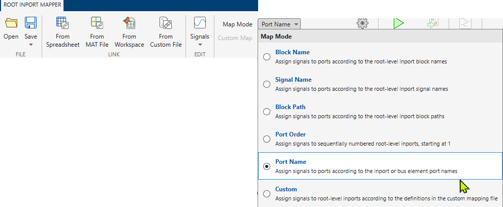
Root Inport Mapper Map Mode with Port Name mode selected.

Corresponding to this change, the mapDataToInport and getSlRootInportMap functions now support the new mapping mode option "PortName".

Signal Editor: Edit signal data faster with synchronized properties and improved performance

In R2026b, the block version of the Signal Editor tool has these changes:

  • When you change and save signal interpolation properties in the Signal Editor tool, the Signal Editor block dialog box updates with the same interpolation properties.

    Existing Signal Editor blocks do not automatically synchronize the values when opened. If you have a Signal Editor block from a model prior to R2026b, the Interpolate data and Unit parameters of the Signal Editor tool only reflect in the Signal Editor block when you edit values in the Signal Editor tool and click Save.

  • When you change and save signal units in the Signal Editor tool, the Signal Editor block dialog box updates with the same updated units.

    Existing Signal Editor blocks do not automatically synchronize the values when opened. If you have a Signal Editor block from a model prior to R2026b, the Interpolate data and Unit parameters of the Signal Editor tool only reflect in the Signal Editor block when you edit values in the Signal Editor tool and click Save.

All versions of the Signal Editor have these changes:

  • Plot data array signals with no interpolation (zero-order hold). In previous releases, the tool plotted data array signals with linear interpolation.

  • In the Inputs signal hierarchy pane, the Select all signals under same scenario option has changed to Select all signals under selected scenarios.

  • The Signal Editor tool performance is faster when viewing and editing signal data in the Signal Editor data table.

Configure one-way client-server communication for service interfaces in data dictionaries

Configure one-way client-server communication at the interface level by selecting the ServerResponseNotRequired property for service interface function elements in the Architectural Data Editor, or programmatically by setting the property to true on Simulink.dictionary.archdata.FunctionElement objects.

The function element must have no output arguments in its prototype before you can set ServerResponseNotRequired to true.

For more information about software component and architecture modeling, see Software Component Modeling.

 Functionality being removed or changed

Warning reported by default when Simulink.data.dictionary.open is unable to open a referenced dictionary

Behavior change

Starting in R2026b, when the Simulink.data.dictionary.open function is unable to open a dictionary referenced by the target dictionary, the function reports a warning, but still opens the target dictionary. The name-value argument SubdictionaryErrorAction has been removed. Previously, the function reported an error unless you called the function with the SubdictionaryErrorAction argument set to "warn".

Compiler warning for classic initialization mode

Warns

Starting in R2026b, Simulink issues a compile time warning if you use the Classic option for the Underspecified initialization detection configuration parameter. Use the Simplified option instead. For more information, see Underspecified initialization detection.

Simplified initialization mode helps to avoid unexpected simulation results and improves consistency. For more information about how to switch from classic to simplified initialization mode, see Convert from Classic to Simplified Initialization Mode.

Block Enhancements

 Simulink DateTime Blocks: Bring calendar date and time natively into Simulink models

Use Simulink DateTime blocks to run simulations at a particular real-world time, work seamlessly with date and time data, and execute time-dependent control logic. Use blocks from the DateTime library when designing satellites, modeling distributed or imperfect timekeeping systems, and scheduling logistics operations. These blocks provide:

  • The ability to specify a real-world calendar date and time at which a model is to be simulated.

  • Support for timestamps stored as integers, doubles, or fixed-point numbers.

  • Semantic support for leap seconds, leap days, Julian dates, and 12- and 24-hour clocks.

  • Support for the TAI, UTC, and TT time standards.

  • Support for loading and logging DateTime data to the MATLAB workspace as MATLAB datetime data.

Simulink DateTime includes these blocks:

To define the reference calendar date and time for a model, see Date and time at simulation time zero.

To create DateTime data types, use the Simulink.DateTimeType object.

To log DateTime data, use signal logging, the Outport block, the Record block, or the To Workspace block.

Starting in R2026b, these blocks support DateTime data types:

In the Simulation Data Inspector, DateTime signals appear as a numeric representation of the underlying DateTime data.

 Conditionally hold signal values using the new Conditional Hold block

The new Conditional Hold block conditionally holds its input signal u based on the value of the Boolean condition signal, h. If the input is a vector, the block holds all elements of the vector.

The block accepts an initial condition, which it uses only at the first time step, when the hold value condition is true and the block has no previous input to hold. Use this block to simplify a common modeling pattern where you might have used multiple blocks.

Enhancements in Scope and Floating Scope

Display measurements data using engineering notation

The Scope, Floating Scope and Scope Viewer display the cursor measurements, peaks, statistics, and bilevel measurements using engineering notation.

Note

The Signal Statistics panel, Peaks panel, and the bilevel measurements panel require a DSP System Toolbox™ or Simscape™ license.
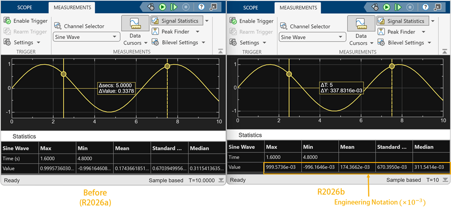
Sinusoidal signal showing cursors and signal statistics. The scope displays the measurements data using the power of 3 in engineering notation.

Access style settings from context menu

You can now also access the style settings of the Scope, Floating Scope and Scope Viewer by right-clicking the scope display and selecting Style.

Support for calendar date and time

You can now visualize the simulation data and the measurements data in Scope, Floating Scope and Scope Viewer using the real-world calendar date and time. For more information on how to enable this support, see the Enable DateTime on T-Axis parameter description in the scope reference page.

New Video: Visualize simulation results with Simulink scopes

Learn how to effectively visualize signal data to explore signal behavior and troubleshoot simulations using the Scope block and Floating Scope in Simulink. In this video, you will learn how to:

  • Add and manage Scopes and Scope Viewers

  • View signal data without cluttering your model

  • Customize scope displays

  • Utilize measurement tools

  • Dock multiple scopes in one window

Here are the links to the video on:

 Signal Editor block: Default signal property source changed to MAT file

Starting in R2026b, the default value of the Use properties from parameter of the Signal Editor block is Signal data in MAT file. In releases before R2026b, the default value was Dialog parameters.

Sqrt block updates

The Sqrt block now supports a Lookup method for the sqrt function. Use the Lookup method if you want a fast, approximate calculation with less resource usage and near floating-point accuracy. Selecting this Lookup method enables the Number of data points parameter, where you can specify the number of data points for the lookup table.

Starting in R2026b, you can use these programmatic parameters to set the Method parameter. Existing models continue to work.

  • SqrtAlgorithmType — For the sqrt function, which includes the Exact and Lookup methods.

  • RsqrtAlgorithmType — For the rsqrt, which includes the Exact and Newton-Raphson methods.

Saturation Block: Output saturation status through new ports block updates

You can enable saturation status ports on the Saturation block by selecting the new Output saturation status parameter.

Blockset Designer: Streamlined editing with context menus and integrated messages

Starting in R2026b, the Blockset Designer has these changes:

  • Error and warning messages are now integrated into the Blockset Designer interface. They no longer appear in separate windows.

  • For the creation of blocks or sublibraries, Blockset Designer now allows you to create the block or sublibrary inline. In previous releases, a dialog box appeared for this operation.

  • For the renaming of library blocks or sublibraries, Blockset Designer allows you to edit the library block or sublibrary name inline. In previous releases, a dialog box appeared for this operation.

Selector and Assignment block updates

Starting in R2026b, by default, the Selector and Assignment blocks check for out-of-range index values in accelerator and rapid accelerator simulation modes. The Check for out-of-range index in accelerated simulation parameter is no longer available to disable these checks. This change enables the blocks to always perform correct and necessary run-time out-of-range index checking.

You can still turn off these checks by programmatically setting the RuntimeRangeChecks property on the Selector or Assignment block. However, if you turn off the check for out-of-range index values in accelerator and rapid accelerator simulation modes, the next time you open the block, the Check for out-of-range index in accelerated simulation parameter appears with a warning.

In previous releases, you used the block dialog Check for out-of-range index in accelerated simulation parameter or RuntimeRangeChecks property to control the check.

Steady State Detection block: Detect when systems reach steady-state operation during simulation

To detect when systems reach steady-state operation during simulation, use the new Steady State Detection block in the Simulink Extras library. The block produces a Boolean output you can use to trigger downstream logic, such as stopping the simulation to save an operating point or switching control logic. The block can detect steady-state operation based on both constant and periodic input signals.

Block parameters define the criteria for steady-state operation as a target, tolerance, and stability window. By default, the block automatically detects the target value or amplitude and period.

C Function block: New block editor

Starting in R2026b, a new C Function block editor is introduced that comes with modern capabilities such as syntax highlighting, auto-indentation, and symbol highlighting. The editor also supports both light and dark themes, and the MATLAB desktop theme determines its appearance.

C Function block: Specify custom code dependencies programmatically

Starting in R2026b, you can specify dependencies for custom C/C++ code in the C Function block using the UpdateBuildInfo option of the Custom Code Location parameter. The dependencies include header files, source files, libraries, directories, compiler flags, macro definitions, and linker flags for the compiler. This enhancement allows you to programmatically specify custom code dependencies in a C Function block for both simulation and code generation purposes.

Display images based on signal values using a customizable MultiStateImage block

You can now display images based on signal values using the new MultiStateImage block from the Customizable Blocks library. The MultiStateImage block pairs state images you provide with state values or ranges of values that you specify. When the value of the connected signal matches a state value or falls within a state value range, the MultiStateImage block displays the corresponding state image.

The block is a more customizable version of the MultiStateImage block from the Dashboard library. With the MultiStateImage block from the Customizable Blocks library, you can:

  • Specify state values as discrete values or ranges.

  • Configure each state individually, or apply the default state settings to all states.

  • Set the position and size of each state image individually.

  • Resize the state images freely by dragging their corners.

  • Add a foreground image, background image, or background color to the block.

View multidimensional signals with Display block

The Display block from the Customizable Blocks library can now display multidimensional signals. Previously, the block could only display scalar signals.

By default, the block displays multidimensional signals in a grid. To set the color of the grid lines, select the block. In the Property Inspector, on the Design tab, in the Text component, select a new color for Grid Color. To turn the grid off, in the same location, toggle the Show grid for non-scalar signals button off.

A Display block displays the value of the signal line connected to a Constant block. The Constant block value is the matrix [5 8; 9 4]. The Display block displays the element values in a grid with green lines.

Set port constraints of masked blocks to accept all numeric data types

Starting in R2026b, you can enable masked blocks to accept any numeric data type by setting the value of the Rule.DataType property of the port constraint to numeric. Previously, to use all numeric data types, you had to specify each numeric type individually when defining a port constraint. For more information, see addPortConstraint.

Evaluate only custom values in Combo Box parameters of masked blocks

When you enable the Evaluate attribute for a combobox mask parameter, Simulink evaluates both predefined and user‑defined values as MATLAB expressions. Starting in R2026b, you can set a combobox mask parameter to evaluate only the custom values you enter.

You can enable the Evaluate only custom values option of a combobox parameter in the Behavior section of the Property Editor pane in the Mask Editor.
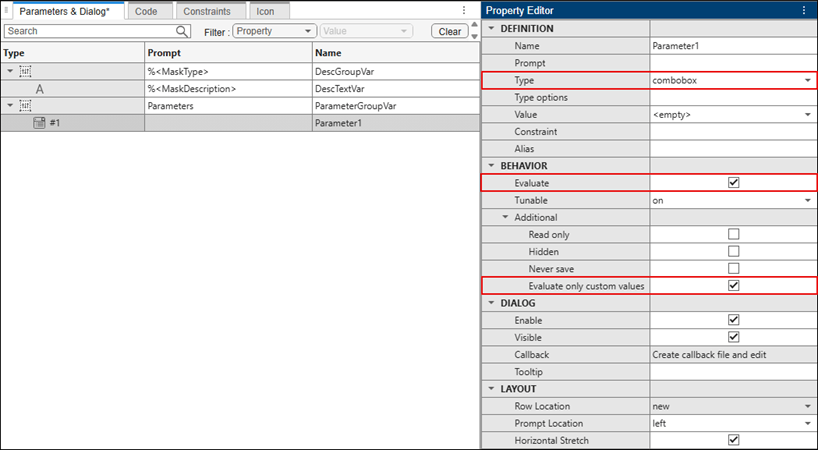
Mask Editor showing a parameter selected in the Parameters pane. In the Property Editor section, the Type is set to combobox and Evaluate only custom values is enabled.

To enable the Evaluate only custom values option from the command line, see Simulink.MaskParameter.Behavior.

Use combo box in Custom Table parameters of masked blocks

Starting in R2026b, you can set the column type in a custom table parameter to combobox from the Mask Editor or programmatically. To set the column type in the Mask Editor, in the Property Editor pane, click Columns, and then set Type to combobox.
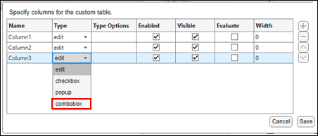
Custom Table column settings dialog showing the Type field set to combobox for a column, with other column properties listed in a table.

To add a combo box column from the command line, see Control Custom Table Parameter Programmatically.

Custom Table parameter callback is optimized

Starting in R2026b, callbacks for custom table mask parameters run only when parameter values change. This change reduces unnecessary callback execution and matches the behavior of other mask parameters.

Parameter Writer Block Support for workspace variables or mask parameters used by Simscape Blocks

Starting in R2026b, you can use the Parameter Writer block to write to base workspace variables, model workspace variables, mask parameters, and Simulink data dictionary variables used by the run-time parameters of Simscape blocks. This capability expands the scope of the Parameter Writer block beyond Simulink blocks. For more information about Simscape run-time parameters, see About Simscape Run-Time Parameters (Simscape).

Improved performance of multi-instance MATLAB System block simulation and code generation

In R2026b, simulation and code generation are faster for models with multiple instances of MATLAB System blocks. In rapid accelerator mode, simulation performance can scale more efficiently as you add instances of MATLAB System blocks because Simulink utilizes code reuse when possible. Code generation performance has also been improved for rapid accelerator, GRT, and ERT workflows through more effective reuse of shared inference results.

Propagate sample rates from FMU ports to connected blocks

Starting in R2026b, sample rates of FMI 3.0 FMUs can propagate from individual FMU ports to connected upstream and downstream blocks based on FMI periodic clock dependencies. This capability allows connected blocks to run at more appropriate rates, which can improve simulation performance, particularly in large models.

This capability is supported for both Model Exchange and Co‑Simulation FMUs when clock‑based sample rate propagation is enabled.

Icon Editor: Add dynamic text, position elements relatively, and inherit domain styles

Starting in R2026b, Icon Editor has these enhancements:

  • Add dynamic text — Add expression text on a masked block icon by using the Expression Text element from the Tools pane. To edit an expression, double-click the Expression Text element on the canvas and write a JavaScript® expression such as "Gain value is " + parameterName. To customize expression behavior, use the options in Expression Text section in the Element Properties pane.

    For more information, see Display Text Dynamically on Block Icon Based on Parameter Values.
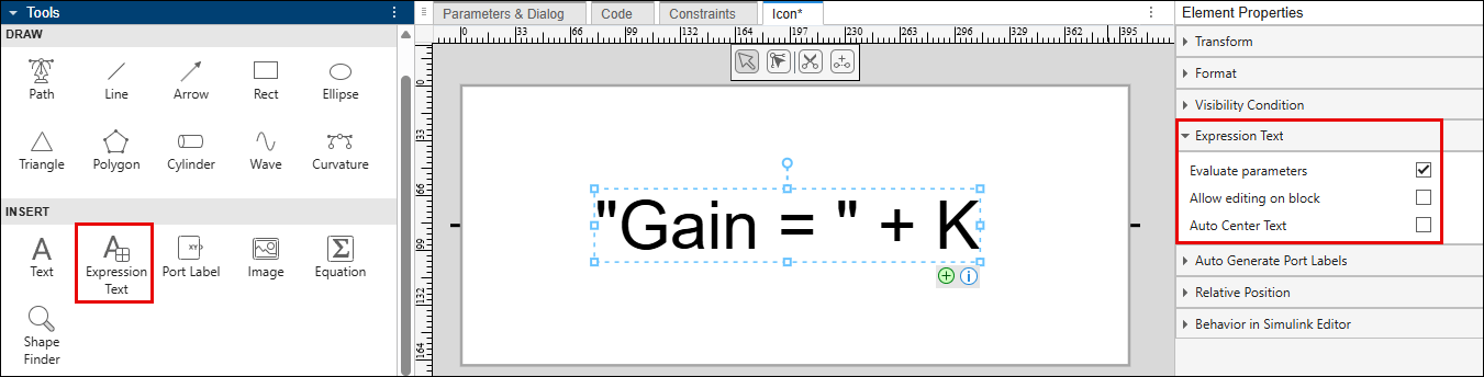
    expression-text

  • Position an icon element relative to another element — The updated Relative Position section in the Element Properties pane now makes it easier to position an element relative to another element or the canvas.

    For more information, see Position Elements Relatively Using Relative Positioning.
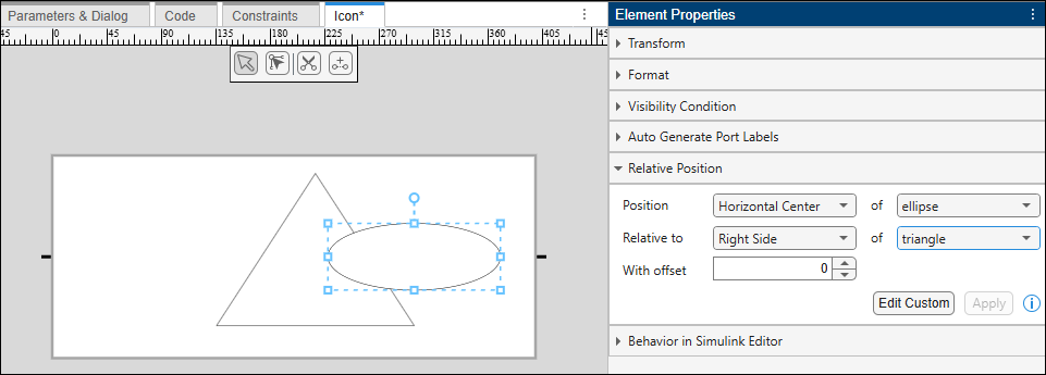
    relative-position-example

  • Inherit domain styles for Simscape block icons — You can now make Simscape block icons inherit port domain styles by using the Inherit Styles option in the Format section. For example, to inherit a style based on a right-side port and the electrical domain for a Variable Resistor block, you would set Inherit Styles to R0: Electrical. Previously, domain styles could be inherited only by using the Port Binding option in the toolstrip.

  • Display port labels on masked block icons — You can now display port labels from the blocks inside the mask directly on masked block icons by selecting the Show port labels from block check box in the Icon Settings section.

View and edit notes for Simulink referenced models and subsystems

Starting in R2026b, you can view and edit notes associated with referenced models and subsystems directly from their corresponding blocks in the parent model.

 Functionality being removed or changed

Previous versions of lookup table blocks permanently removed

Previous versions of these lookup table blocks are removed in R2026b. Use the listed replacement blocks instead.

Previous BlockReplacement Block

PreLookup Index Search

Prelookup

Interpolation (n-D) Using PreLookup

Interpolation Using Prelookup

When you load a model that contains the PreLookup Index Search or Interpolation (n-D) Using PreLookup blocks, Simulink automatically replaces these blocks with the Prelookup and Interpolation Using Prelookup blocks.

  • If the PreLookup Index Search and Interpolation (n-D) Using PreLookup blocks were directly connected, the automatic replacement should have no issues.

  • If the PreLookup Index Search and Interpolation (n-D) Using PreLookup blocks were not directly connected, when the blocks are loaded or the model is compiled, Simulink checks for incompatible signal lines and other compatibility issues. When prompted, click suggested fix-it actions.

When you resave the model, the model is saved with the new blocks.

Lookup Table Dynamic block to be removed

Behavior change in future release

The Lookup Table Dynamic block will be removed in a future release. Use the 1-D Lookup Table block with the Table data or Breakpoints > Source parameters set to Input port instead.

Lookup Table and Lookup Table (2-D) blocks to be removed

Behavior change in future release

The Lookup Table and Lookup Table (2-D) blocks will be removed in a future release. Use the replacement blocks listed in the table instead. For more information, see Update Lookup Table Blocks to New Versions.

Current BlockReplacement Block

Lookup Table

1-D Lookup Table

Lookup Table (2-D)

2-D Lookup Table

These blocks are compatible with the replacement blocks.

Selector and Assignment block out-of-range check behavior change

Behavior change

Starting in R2026b, the Selector and Assignment blocks check for out-of-range index values in accelerator and rapid accelerator simulation modes by default. The dialog box Check for out-of-range index in accelerated simulation parameter for the Selector and Assignment blocks is now hidden and can only be programmatically enabled by using the RuntimeRangeChecks property.

If you load an existing model with these checks turned off, a warning appears stating that the .setting is not recommended. The model continues to run.

Signal Editor block default change

Behavior change

Starting in R2026b, the default value of the Use properties from parameter of the Signal Editor block is now Signal data in MAT file. In releases before R2026b, the default value was Dialog parameters. Starting in R2026b, the Interpolate data, Unit, Apply signal properties to all scenarios and Apply signal properties to all signals are read-only by default. If you have applications that set these values programmatically using the SignalPropertySource property, the application might now return an error.

To modify the Interpolate data and Unit settings of signals, take one of these actions:

  • From the Signal Editor block, start the Signal Editor tool and modify the signal properties in that interface.

  • Load the MAT file associated with the Signal Editor into the workspace, modify the data, and save the data back to the MAT file.

  • Set Use properties from back to Dialog parameters to override the data settings with the Interpolate data and Unit parameter values.

Signal Builder block warning

Starting in R2026b, adding the Signal Builder block to a model returns a warning.

Connection to Hardware

Support for PWM and ADC interrupts on Teensy boards

The new PWM and Analog Input blocks for Teensy 4.0 and 4.1 boards enable hardware PWM and ADC interrupts.

The PWM block supports hardware timer-based interrupts, including:

  • PWM overflow interrupts

  • Compare-match interrupts

These interrupts allow the model to respond precisely to PWM timer events supporting timer-critical control and synchronization scenarios.

The Analog Input block supports end-of-conversion (EOC) interrupts. EOC interrupts let the model execute application logic immediately after an analog-to-digital conversion completes, improving responsiveness and timing accuracy.

You can attach interrupt handlers using the Hardware Interrupt block and execute control algorithms from interrupt service routines. These blocks require Embedded Coder.

For applications that use these blocks, see Open-Loop Control to Sensorless FOC of PMSM on Teensy Hardware.

Support for fast serial logging on Arduino boards

Simulink Support Package for Arduino® Hardware now supports frame-based serial logging support to the Serial Transmit block. Frame-based logging improves data logging reliability when the transmit rate of the target model is higher than the receive rate of the host model.

The Serial Transmit block includes a new Enable frame size parameter. When you enable this option, the block exposes a Frame size parameter that lets you specify the number of data samples to package and transmit as a single frame. This framing approach helps make serial data transfers robust and efficient for high-rate control and logging applications where conventional serial logging or external mode over serial is not suitable.

For applications that use frame-based serial logging for high-rate motor control data visualization, see Open-Loop Control to Sensorless FOC of PMSM on Teensy Hardware.

Motor control series for PMSM using Teensy hardware: Reference Examples

The support package includes a new series of reference examples that show how to implement sensorless field-oriented control (FOC) of a permanent magnet synchronous motor (PMSM) using a Teensy development board and a DRV8305EVM inverter. The series progressively builds motor control concepts from basic open-loop operation to advanced closed-loop sensorless FOC. These examples use the new PWM and Analog Input blocks with Hardware Interrupt support and frame-based serial logging.

Support for MAT-file logging on Teensy boards

Simulink Support Package for Arduino Hardware now supports logging data directly to MAT files on SD cards when using Teensy 4.0 and 4.1 hardware. Recording MAT files on your target hardware lets you analyze data in Simulink without manual file conversion.

The support package adds new configuration options for MAT-file logging when you select Teensy 4.0 (arduino Compatible) or Teensy 4.1 (arduino Compatible) options in the Configuration Parameters dialog box.

  • For Teensy 4.0 boards, you can log data using an external SD card module connected through a serial peripheral interface (SPI).

  • For Teensy 4.1 boards, you can log data using the on-board SD card interface or an external SD card module connected through an SPI.

To enable MAT-file logging, in the model configuration parameters, in the Hardware Implementation pane, set Hardware board to your Teensy board. Then, in the Code Generation pane, go to Interface and expand Advanced parameters and select MAT-file logging. For more information, see Working with Arduino SD Card File Read Blocks.

Support for XCP over CAN on Arduino boards

You can now use XCP over CAN for external mode monitoring and calibrating with these boards.

  • Arduino Due

  • Teensy 4.0 and 4.1

  • Arduino Uno R4 Wi-Fi® and Minima

  • Arduino Nano R4

This capability allows you to tune parameters, monitor signals over CAN, and generate A2L files for use with third-party calibration tools from vendors such as Vector, Kvaser, PEAK-System, and NI™ (NI-XNET).

Using XCP over CAN requires Vehicle Network Toolbox™ and supported external CAN hardware. For more information, see Set Up, Deploy, and Calibrate Arduino Application Using XCP on CAN, Generate A2L File for Third-Party Calibration Tools Using XCP on CAN Host Communication, and External mode.

Support for variable length UDP payloads and blocking receive mode on Arduino

The WiFi UDP Send and WiFi UDP Receive blocks now support variable-length UDP payloads, enabling models to transmit and receive data whose size changes at run time. Previously, these blocks supported only fixed-length data exchange.

Additionally, the WiFi UDP Receive block now supports blocking and non-blocking modes. These modes control block behavior when no packet is available.

  • Blocking mode — Wait for incoming data up to a specified timeout.

  • Non-blocking mode — Do not wait.

The new Status port indicates whether data was received, unavailable, or if a timeout occurred.

Processor-in-the-loop support for Raspberry Pi Pico and ESP32 boards

This release adds PIL support for the following Arduino-compatible boards:

  • Raspberry Pi® Pico

  • Raspberry Pi Pico W

  • ESP32-WROOM

  • ESP32-WROVER

  • ESP32-S3 series

You can now use PIL with these boards to verify target-specific code behavior, perform execution-time profiling, and evaluate algorithm performance before deployment. For more information, see Code Verification and Validation with PIL on Arduino Hardware.

Support for Arduino Nano R4 board

You can now use Simulink Support Package for Arduino Hardware to design, run, and deploy models to the Arduino Nano R4 board.

To use this board, in the model configuration parameters, in the Hardware Implementation pane, set Hardware board to Arduino Nano R4. For more information, see Supported Arduino and Arduino Compatible Hardware — Simulink Support Package for Arduino Hardware.

Support added for Arduino compatible ESP32-S3 board

You can now use Simulink Support Package for Arduino Hardware to design, run, and deploy models to these ESP32-S3 modules and boards:

ModuleBoard

ESP32-S3-WROOM-1/1U

ESP32-S3-DevKitC-1

ESP32-S3-WROOM-2/2U

ESP32-S3-DevKitC-1

ESP32-S3-MINI-1/1U

ESP32-S3-DevKitM-1

To use these modules and boards, in the model configuration parameters, in the Hardware Implementation pane, set Hardware board to ESP32-S3 Series (Arduino Compatible). Then, in the Target hardware resources, select ESP32-S3 board properties to select the target board and its supported module or development kit variant.

Support for Arduino Nano ESP32 board

You can now use Simulink Support Package for Arduino Hardware to design, run, and deploy models on Arduino Nano ESP32 boards.

To use this board, in the model configuration parameters, in the Hardware Implementation pane, set Hardware board to Arduino Nano ESP32. For more information, see Supported Arduino and Arduino Compatible Hardware — Simulink Support Package for Arduino Hardware.

MATLAB Function Blocks

Code generation for more toolbox functions

In R2026b, you can generate code for additional toolbox functions and objects. For a list of all functions and objects that are supported for code generation, see:

These are links to the release notes of some toolboxes that added code generation support in R2026b:

Image Processing Toolbox

See C Code Generation: Generate code from additional functions using MATLAB Coder (Image Processing Toolbox).

Statistics and Machine Learning Toolbox

See Generate C/C++ code for prediction using a custom neural network architecture (requires MATLAB Coder and Deep Learning Toolbox) (Statistics and Machine Learning Toolbox).

Wavelet Toolbox

See Deep Learning: Code generation for discrete wavelet transform (Wavelet Toolbox).

Modeling Guidelines

Modified modeling guidelines

Starting in R2026b, the following changes apply to the modeling guidelines.