R2026b

New Features, Bug Fixes, Compatibility Considerations

View Consistent Sample Time Colors and Annotations Across Model Reference Hierarchies

Sample time colors, annotations, and the Timing Legend now remain consistent across a top model and its referenced models. The top model defines the timing context for the hierarchy. When you open a referenced model from the top model, it inherits sample time colors, annotations, and Timing Legend entries based on the top model's context. When opened as the top model, a referenced model uses its own independent timing context.

Toggling these overlays for any model in the hierarchy updates the visualization across the entire hierarchy, making it easier to inspect the timing behavior.

There are some limitations where this synchronization is not possible and referenced models use their own compiled timing information.

simulinkScreenshot function: Take a screenshot of a Simulink model or subsystem

Use the simulinkScreenshot function to take a screenshot of a Simulink® model or subsystem and display it in a figure window.

For example, this code loads the sf_car model and takes a screenshot of it.

load_system("sf_car");
simulinkScreenshot("sf_car");
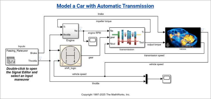
Screenshot of a model with the title "Model a Car with Automatic Transmission"

Simulink settings integrated into MATLAB settings

Behavior change

Starting in R2026b, Simulink settings are integrated into MATLAB® settings. Instead of appearing in a separate dialog box, Simulink settings are now located on panes in the MATLAB Settings dialog box.

You can still access Simulink settings from the Simulink Toolstrip. On the Modeling tab, select Environment > Simulink Settings. The MATLAB Settings dialog box opens to the Simulink pane, where you can specify general Simulink settings. To view editor or model file settings, in the navigation pane, expand Simulink and select Editor or Model File.

Using this command to open the Simulink settings is no longer supported.

slprivate('showprefs')

Instead, use this command to open the MATLAB Settings dialog box, and then select Simulink.

preferences
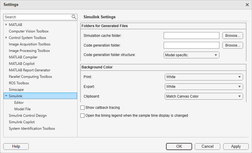
Simulink settings in the MATLAB Settings dialog box

Provide feedback on your experience in Simulink and Stateflow

Starting in R2026b, you can provide suggestions for improving Simulink and Stateflow® from the Simulink Editor. In the Simulink quick access bar located in the upper right corner of the editor, click the Feedback button.
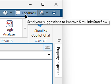
Feedback button in the Simulink quick access toolbar with this tooltip: "Send your suggestions to improve Simulink/Stateflow"

Use Quick Mode in Finder to search model elements without loading references and libraries

Use Quick Mode in the Finder to search for model elements of the current system without loading referenced models or libraries. By searching without loading references, Quick Mode reduces search time for large model hierarchies.

In Quick Mode, the Finder displays matches from unloaded references as grayed-out results. Double-click a result to load references and view additional matches. Starting in R2026b, Quick Mode is the default search mode in Finder.

For more information, see Search Using Quick Mode.
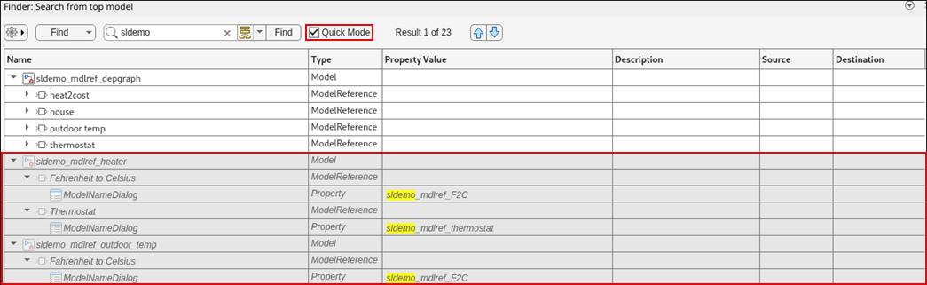
unloaded-references

Simulation Analysis and Performance

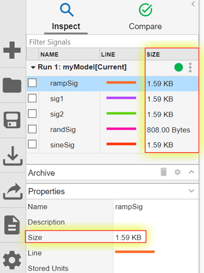
 Organize signal visualizations using tabs in the Simulation Data Inspector

You can now organize your visualizations in the Simulation Data Inspector using up to eight independent tabs, each with its own subplot layout and settings. You can:

  • Add tabs with the New Tab button .

  • Reorder tabs by dragging.

  • Rename, close, or change tab color by right-clicking.

To manage tabs programmatically, use the Simulink.sdi.TabGroup object. This object is a container for Simulink.sdi.Tab objects, each representing an open tab in the Simulation Data Inspector. To create, access, and manage tabs, use these functions with the Simulink.sdi.TabGroup object:

To manage individual tabs, use these functions with the Simulink.sdi.Tab object corresponding to the tab of interest:

 Analyze Simulink Profiler and Solver Profiler results using AI

To simplify and speed up performance analysis, generate AI explanations of profiling results from the Simulink Profiler and Solver Profiler.

  • The Simulink Profiler AI explanation summarizes key findings and identifies potential bottlenecks in the simulation.

  • The Solver Profiler AI explanation summarizes key findings, identifies potential bottlenecks, and provides actionable recommendations to improve simulation performance.

To generate AI explanations of profiling results, you must have a Simulink Copilot license.

Techniques to Speed Up Simulink Simulations: Self-paced, interactive course available as part of Online Training Suite subscription

Techniques to Speed Up Simulink Simulations is a new course that teaches you to:

  • Analyze models for configuration parameter settings that impact simulation performance using the Performance Advisor.

  • Analyze solver behavior that impacts simulation performance using the Solver Profiler.

  • Identify blocks and subsystems that contribute most to the overall compilation and execution time using the Simulink Profiler.

  • Choose appropriate simulation modes to accelerate the simulation of model reference hierarchies.

  • Avoid recompilation in batch and iterative simulations by using fast restart.

For more information, see Techniques to Speed Up Simulink Simulations.
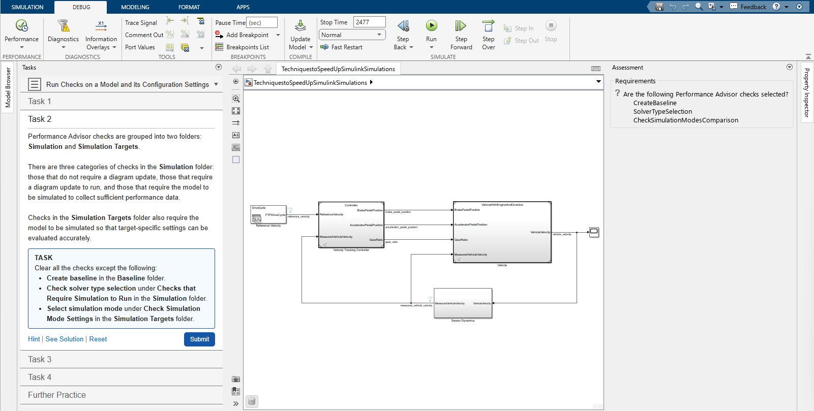
Interactive task in Techniques to Speed Up Simulink Simulations

Plugin Solvers: Write custom fixed- or variable-step explicit and implicit solvers for Simulink simulations

To write custom solvers for Simulink simulations, use the Simulink.Solver.FixedStepSolver and Simulink.Solver.VariableStepSolver base classes. During simulation, the solver integrates continuous states and advances time. Using the plugin solver interface, you can write custom integration algorithms to solve systems of ordinary differential equations (ODEs) and differential-algebraic equations (DAEs). To implement a plugin solver, you define the integration algorithm in the step method of the solver class. The Simulink simulation environment provides solver services, such as zero-crossing detection.

Plugin solvers do not support:

  • Rapid accelerator simulation

  • Software-in-the-loop (SIL) and processor-in-the-loop (PIL) simulation

  • Deployment with Simulink Compiler™

  • Production code generation using Simulink Coder™ or Embedded Coder®

Local Solver Analyzer: Configure and profile local solvers in model hierarchies

Using the new Local Solver Analyzer, you can:

  • Visualize a model reference hierarchy.

  • Enable, disable, and configure local solvers in referenced models.

  • Profile one or more local solvers in the model hierarchy.

To open the Local Solver Analyzer, open the Solver Profiler. Then, in the toolstrip, in the Analyze section, click Local Solver.

When you profile local solvers, the Local Solver Analyzer displays a summary of the profiling results. To analyze the profiling results, view the profiling data in the Local Solver Profiler. The Local Solver Profiler provides the same data and visualizations as the Solver Profiler but does not support running profiling simulations. To profile a local solver, you must simulate the top model.

Speed up simulations by solving algebraic loops as differential-algebraic equations

You can now solve algebraic loops as differential-algebraic equations (DAEs). In some cases, solving an algebraic loop as a system of DAEs can significantly speed up simulations because solving the loop does not invoke the algebraic loop solver.

To specify how the software solves an algebraic loop, use the new Equation format parameter of the Algebraic Constraint block. To solve the loop as a DAE, set Equation format to Differential Algebraic Equation.

For information about when to solve algebraic loops as DAEs, see Algebraic Constraint.

Set breakpoints on outputs of virtual subsystems while stepping block by block

While debugging a simulation block by block, you can now add breakpoints to the outputs of virtual subsystems, including masked subsystems and custom blocks implemented as masked subsystems. The simulation pauses when the output of the nonvirtual source block for the port satisfies the breakpoint condition.

When the simulation pauses on one of these breakpoints:

  • The virtual subsystem is highlighted green in the block diagram.

  • The Breakpoints List highlights the row for the breakpoint.

  • The status bar shows the path to the virtual subsystem.

If multiple breakpoints on virtual subsystem outputs share the same source block, all associated subsystems are highlighted in the block diagram. The Breakpoints List highlights the rows for all the breakpoints.

In previous releases, you could add breakpoints on the outputs of virtual subsystems, but the breakpoints did not pause the simulation and appeared as invalid in the block diagram. To pause the simulation based on the signal value, you had to add a breakpoint on the nonvirtual source block that produces the output.

Import data from Parquet files into the Simulation Data Inspector

You can now import simulation data from Parquet files into the Simulation Data Inspector, complementing the Parquet export capability introduced in R2026a. This new import capability includes selective signal loading to bring in only the data you need for comparison and analysis. You can import scalar and multidimensional signals with real and complex data of any built-in data type, as well as enumerations, strings, fixed-point data, buses, and arrays of buses.

When a JSON sidecar file exists in the same directory as the Parquet file, the Simulation Data Inspector automatically detects it and applies the signal metadata and multi-run information from the sidecar.

To inspect the contents of a Parquet file before importing, use these new functions:

For more information, see Parquet File Format for Simulation Data.

Stream data in the Simulation Data Inspector when logging last n signal values

The Simulation Data Inspector now streams data during simulation when you log only the last n signal values using the Limit data points to last parameter. Before R2026b, when you configured logging to capture only the last n signal values, the Simulation Data Inspector did not stream data during simulation.

Export simulation data to CSV files from the Simulation Data Inspector

You can now export logged simulation data from the Simulation Data Inspector to CSV files. You can export data using shared or individual time columns. You can also include metadata such as units, data types, block paths, interpolation method, and port index. You can export data of any built-in numeric type, as well as enumerations, fixed-point data, complex signals, buses, and multidimensional signals. For more information, see Export Data to CSV File.

Import additional data types and metadata from CSV files into the Simulation Data Inspector

The Simulation Data Inspector now provides expanded CSV import capabilities. You can import CSV files that contain richer signal metadata, multiple runs, and additional data types. The expanded import matches the R2026b CSV export, so you can export and reimport simulation data using CSV files.

For more information, see CSV File Format for Simulation Data.

Export simulation data to value change dump (VCD) files for HDL verification

You can now export simulation data from the Simulation Data Inspector to VCD format. VCD files are compatible with HDL verification tools such as ModelSim, Questa, and GTKWave, enabling you to compare Simulink behavioral models with HDL simulations. For more information, see Export Data to VCD File.

Export time-varying parameters to Excel files from the Simulation Data Inspector

You can now export parameter data that changes over time from the Simulation Data Inspector to Microsoft® Excel® files.

Specify component when unpacking targets from Simulink cache file

You can now unpack component and subcomponent artifacts from the Simulink cache file for a software component model configured for SOA application deployment by specifying a Component name-value argument when using the slxcunpack function.

 Functionality being removed or changed

Record logged workspace data in Simulation Data Inspector parameter will be removed

Still runs

The Record logged workspace data in Simulation Data Inspector configuration parameter will be removed in a future release. This parameter sends data logged in a format other than Dataset and data logged using the To File block to the Simulation Data Inspector when a simulation pauses or stops. After removal, this data will no longer be sent to the Simulation Data Inspector. This change will not affect data logged using the Dataset format.

Component-Based Modeling

 Reference published models for faster simulation

To speed up simulation, you can now reference published models. These ready-to-run versions of Simulink models contain build artifacts that Simulink unpacks and uses as needed. Simulink skips rebuild checks for published models, reducing model compilation and build overhead.

With published models, you can:

  • Log signals that the author configured for logging.

  • Tune parameters.

  • Unpack the original data sources, such as data dictionaries.

  • Provide an alternate value source for external parameters.

  • Unpack supplemental files included by the author, such as instructions, test results, and code coverage reports.

For more information, see Reference Published Models.

While using a published model typically requires only a Simulink license, creating a published model requires a Simulink Coder license. For more information, see Publish Models to Speed Up Simulation and Code Generation (Simulink Coder).

 Software Component Designer: Design, simulate, and deploy software components for service-oriented architecture applications

In R2026b, the Software Component Designer for Simulink support package provides a model-based workflow for designing software components for service-oriented architectures (SOA). You can develop, validate, and deploy software components independently before integrating them into larger systems. Using the Software Component Designer app, you can configure a Simulink model as a software component model, define data and service interfaces, configure quality of service (QoS) properties, and validate component behaviors using test harnesses.

Key capabilities of the Software Component Designer app include:

  • Define software components — Configure a Simulink model as a software component model and define data and service interfaces using the Interface Editor.

  • Configure QoS properties — Configure communication and execution properties on port elements to model send-receive and client-server communication patterns at the component level.

  • Component-level testing — Validate component behaviors before integration into compositions by generating test harnesses for software component models (requires Simulink Test™ and System Composer™).

  • Code generation and deployment — Generate fully deployable applications for Linux® platforms from software component models, including service implementation and middleware bindings for DDS and SOME/IP (requires Embedded Coder).

For more information, see Software Component Models in Simulink.

For an example, see Model and Simulate Services of Brake Control System.

In R2026b, the Simulink Variant Manager™ product replaces the Variant Manager for Simulink support package.

The Simulink Variant Manager user interface, command-line API, and workflows remain the same as in the Variant Manager for Simulink support package. Existing models and scripts continue to work without changes.

For more information, see Simulink Variant Manager (Simulink Variant Manager).

Rename elements of ports programmatically

To rename elements of bus element ports at subsystem and model interfaces, you can use the new renameElementOfPort function. For more information and examples, see renameElementOfPort.

Use improved programmatic name for model configuration parameter

The model configuration parameter ModelReferencePassRootInputsByReference (Pass fixed-size scalar root inputs by value for code generation) now has the programmatic name ModelReferencePassRootInputsByValue. The name better matches the dialog box name and the programmatic settings of the new name match the settings of the dialog box.

There are no plans to remove support for references to the existing programmatic name. Its settings remain the same.

Faster model update for Multiversion Co-Simulation components

Starting in R2026b, Multiversion Co-Simulation components update faster when you rebuild models without structural changes. Simulink reuses cached artifacts to avoid redundant computations during model update.

Use blocks with enable methods inside variant choices of run-time Variant Subsystem block

You can now use blocks with enable methods inside the variant choices of a Variant Subsystem block with the Variant activation time parameter set to runtime. An enable method is called just before a block starts executing. Examples of blocks with enable methods include:

  • Stateflow charts

  • Enabled Subsystem blocks

  • Function-Call Subsystem blocks

  • Triggered Subsystem blocks

For more information on run-time variants, see Control Active Choice of Variant Subsystem During Simulation or Execution of Generated Code.

Add bus element blocks as interface ports on Variant Subsystem and Variant Assembly Subsystem blocks

Starting in R2026b, you can use In Bus Element and Out Bus Element blocks as input and output ports on Variant Subsystem or Variant Assembly Subsystem blocks, alongside existing port types Inport, Outport, Connection Port (Simscape), and control ports Enable, Trigger, and Reset.

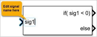
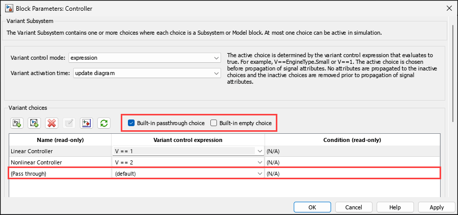
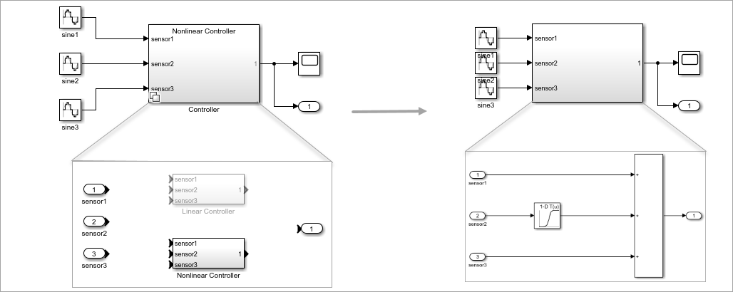
For example, consider a Variant Subsystem block Controller. The first input port of the Controller block is an In Bus Element block named sensorInputs that groups related signals speed, position, and temperature. The second input port is also an In Bus Element block named operationMode that groups related signals type and status. The Controller block has two variant choices, Linear Controller and Nonlinear Controller. Each variant choice contains corresponding input ports for sensorInputs and operationMode.

When you simulate the model, Simulink maps the In Bus Element blocks between Controller and its variant choices by matching the port names sensorInputs and operationMode so that the correct signals route to each variant choice.

Variant Subsystem block Controller with In Bus Element ports, containing two variant choices

When using bus element ports in a Variant Subsystem or Variant Assembly Subsystem block, these restrictions apply:

  • Bus element block port names at the Variant Subsystem interface must be unique.

  • Routing individual bus elements to each variant choice is not supported. In Bus Element and Out Bus Element blocks must specify the bus port.

  • Unlike Outport blocks, the Specify output when source is unconnected and Output function call parameters are not available for Out Bus Element blocks in a Variant Subsystem block.

Suppress variant choice diagnostics for inactive child Variant Subsystem blocks when parent is inactive

In a child Variant Subsystem block, when neither the Built-in empty choice nor the Built-in passthrough choice parameter is selected, the block requires at least one active variant choice during simulation.

Starting in R2026b, for child Variant Subsystem blocks where neither parameter is selected, Simulink evaluates the variant control expressions of the parent block and the child Variant Subsystem block before reporting a diagnostic. If the child Variant Subsystem block is inactive because its parent block is inactive, Simulink suppresses the diagnostic, as the inactive state is inherited and does not require resolution. Diagnostics are reported only when the variant control expressions of the parent and child blocks indicate a configuration that requires action. For example, when the variant control expressions do not overlap and the child Variant Subsystem block can never become active under any parent condition.

Previously, Simulink reported a diagnostic for every inactive child Variant Subsystem block that had no active variant choice, regardless of whether the parent block was also inactive. This behavior produced diagnostics in cases where the child block inherited its inactive state from the parent block and no resolution was needed.

The table demonstrates how the relationship between variant control expressions of the parent block and child Variant Subsystem block determines whether diagnostics for inactive child blocks are reported or suppressed.

RelationshipParent Variant Control ExpressionChild Variant Control ExpressionDiagnostic Behavior
Variant control expressions of child block are equal to those of the active variant choice of the parent.

V == 1 || V == 2

V == 1 || V == 2

Diagnostic is suppressed.
Variant control expressions of child block are mutually exclusive from those of the active variant choice of the parent.

V == 1 || V == 2

V == 3 || V == 4

Diagnostic is reported.
Variant control expressions of child block are a subset of the active variant choice of the parent.

V == 1 || V == 2

V == 2

Diagnostic is reported only when the variant choice of the parent is active.
Variant control expressions of child block are a superset of those of the active variant choice of the parent.

V == 1

V == 1 || V == 2

Diagnostic is suppressed.

Consider the Nonlinear Controller block, which is a variant choice within the Variant Subsystem block Controller, and which has a variant control expression V == 2 || V == 3. Inside this block, there is a child Variant Subsystem block saturationLogic with the variant control expression V == 2 || V == 4.

  • If you set the variant control variable V to 1, both the parent Nonlinear Controller block and child saturationLogic block are inactive. Simulink suppresses diagnostics for the child block because its inactivity is inherited from the inactive parent.

  • If you set V to 2, both the parent and child blocks are active. No diagnostic is reported.

  • If you set V to 3, the parent block Nonlinear Controller is active. The child block saturationLogic remains inactive since V == 3 does not satisfy the variant control expression of the child block. Simulink reports a diagnostic for the child block because it is expected to be active when the parent is active, but no valid variant choice is selected.

Variant Subsystem block Controller with Nonlinear Controller as a variant choice containing child Variant Subsystem block saturationLogic

Simulate Variant Subsystem blocks with activation time set to update diagram analyze all choices as virtual subsystems

Starting in R2026b, Simulink treats Variant Subsystem blocks with the Variant activation time parameter set to update diagram analyze all choices as virtual subsystems. With this change, Simulink detects delays in feedback loops that contain these blocks and reports only true algebraic loops.

In previous releases, these blocks were treated as nonvirtual subsystems, which could lead to the detection of artificial algebraic loops in feedback loops and prevent these optimizations.

Variant Subsystem blocks with code compile, startup, or runtime activation times remain atomic, as these activation times determine the active variant choice after the update diagram time and the active variant choice may change in a later phase.

For more information, see Virtual and Atomic Behavior of Variant Subsystem Blocks for Different Activation Times.

Use Simulink.DataStore object to define data stores

Starting in R2026b, you can use the Simulink.DataStore object to define data stores with support for data store references, diagnostic checks, and sharing across model references. This object makes it easier to manage and access large numbers of data stores in a model.

Previously, you could use Simulink.Signal object to define data stores. However, the Simulink.Signal objects do not provide Data Store Memory block capabilities such as Data store reference, Share across model instances and Diagnostics.

Change the active choice of variant parameters and variant parameter banks during simulation or execution of generated code

You can now change the active choice of variant parameters (Simulink.VariantVariable objects) and variant parameter banks (Simulink.VariantBank objects) during simulation or execution of the generated code. To enable run-time activation, set the ActivationTime property in the associated Simulink.VariantControl object to 'runtime'. Then, switch the active variant by modifying the value of the variant control variable.

To write to the variant control variable, you can use either of these options:

  • Place a Parameter Writer block inside a conditionally executed subsystem or in an event function. Each time the Parameter Writer block writes to the variant control variable, the generated code calls a separate method that switches the active variant parameter value or the active pointer variable used by the variant parameter bank.

  • Use the setVariable function of a Simulation object (while simulation is paused). The generated code that switches the active variant appears in the model step or model output function (depending on the code structure) before the variant is used.

Use symbolic dimensions in variant parameters for AUTOSAR code generation

Starting in R2026b, you can use symbolic dimensions to specify array sizes for variant parameters (Simulink.VariantVariable) in models configured for AUTOSAR code generation. In the generated C code, the code generator uses the symbolic dimension as a system constant to size the variant parameter arrays.

To define a symbolic dimension, add a system constant in the Architecture Data section of a Simulink data dictionary linked to the AUTOSAR component. Set the Specification property of the variant parameter to an AUTOSAR.Parameter object, and set the dimensions of this object to reference the system constant name. Define the variant control as a Simulink.VariantControl object. Set the value of the object to an AUTOSAR.Parameter object mapped to a system constant, and set the activation time to code compile. Code generation exports the symbolic dimension and the variant control as system constants and the variant choices as variation point proxy entries in the generated ARXML. For more information, see Configure Variant Parameter Values for AUTOSAR Elements (AUTOSAR Blockset).

In this example, the model uses a variant parameter K, defined as a Simulink.VariantVariable with two choices. The conditions for the choices are defined as Simulink.VariantExpression objects VExpr_Cond1 and VExpr_Cond2, which represent the variant control expressions V == 1 and V == 2, respectively. The Specification property of K is set to an AUTOSAR.Parameter object KSpec with its dimensions set to [1,P], where P is a system constant from the architecture data that specifies the symbolic dimension.

Model shows a Gain block that uses variant parameter K to scale the input signal

The model defines the variant parameter K and its associated objects in the Design Data section of a Simulink data dictionary. The data dictionary defines the system constant P in the Architecture Data section. For more information on defining system constants in the Architecture Data section, see Manage AUTOSAR Architectural Data With Data Dictionaries (AUTOSAR Blockset).
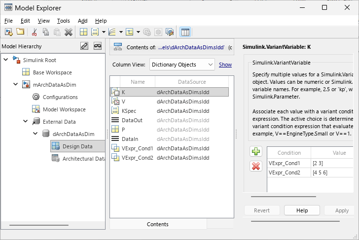
Model Explorer shows variant parameter K with choices for conditions VExpr_Cond1 and VExpr_Cond2

When you generate code for this model, the stub file Rte_Cfg.h defines the system constants for the symbolic dimension P, the variant control V, and the variation points.

/* File: Rte_Cfg.h */

/* Variation points */
#define Rte_SysCon_VExpr_Cond1         (V == 1)
#define Rte_SysCon_VExpr_Cond2         (V == 2)

#define P                              3
#define Rte_SysCon_P                   P
#define V                              2
#define Rte_SysCon_V                   V

The header file mArchDataAsDim.h uses the system constant Rte_SysCon_P as the symbolic dimension for the variant parameter array K. The #if preprocessor conditionals guard the variant parameter definition based on the variant control.

/* File: mArchDataAsDim.h */

/* PublicStructure Variables for Internal Data, for system '<Root>' */
typedef struct {
  float64 Output1[Rte_SysCon_P];       /* '<Root>/Gain2' */
} ARID_DEF_mArchDataAsDim_T;

/* Parameters (default storage) */
struct P_mArchDataAsDim_T_ {

#if Rte_SysCon_VExpr_Cond1 || Rte_SysCon_VExpr_Cond2

  sint16 K[Rte_SysCon_P];              /* Variable: K
                                        * Referenced by: '<Root>/Gain2'
                                        */
#endif
};

The source file mArchDataAsDim.c assigns the values for each choice of the variant parameter. The code conditionally compiles the values based on the variant control V.

/* File: mArchDataAsDim.c */

/* Block parameters (default storage) */
P_mArchDataAsDim_T mArchDataAsDim_P = {

#if Rte_SysCon_VExpr_Cond1 || Rte_SysCon_VExpr_Cond2

  /* Variable: K
   * Referenced by: '<Root>/Gain2'
   */
#if Rte_SysCon_VExpr_Cond1

  { 2, 3 }
#elif Rte_SysCon_VExpr_Cond2
  { 4, 5, 6 }
#endif
#endif
};
The step function uses the symbolic dimension Rte_SysCon_P to iterate over the variant parameter array.
/* File: mArchDataAsDim.c */

/* Model step function */
void mArchDataAsDim_Step(void)
{
  ...
  for (i = 0; i < Rte_SysCon_P; i++) {
    mArchDataAsDim_ARID_DEF.Output1[i] = (float64)mArchDataAsDim_P.K[i] *
      tmpIRead[i];
  }
  ...
}

Run SIL and PIL simulations for models with variant parameter banks

Starting in R2026b, you can run software-in-the-loop (SIL) and processor-in-the-loop (PIL) simulations on models that use variant parameter banks (Simulink.VariantBank objects) to group variant parameters. Previously, SIL and PIL simulations were not supported for models with variant parameter banks.

This capability is supported only for variant parameter banks defined in the base workspace or in a Simulink data dictionary. You can set the top model or a Model block to SIL or PIL simulation mode when variant parameter banks are used in a single model or shared across a model reference hierarchy. You can also use test harnesses to verify models with variant parameter banks in SIL or PIL mode and to run fast restart simulations to test different variant choices without rebuilding the generated code.

For more information, see Simulink.VariantBank and SIL and PIL Simulations (Embedded Coder).

Generate code with inlined default parameter behavior for variant parameters initialized by a Parameter Writer block

Starting in R2026b, you can generate code for models where a Parameter Writer block writes to a Simulink.VariantControl object used by variant parameters (Simulink.VariantVariable objects) when you set the Default parameter behavior model configuration parameter to Inlined. Previously, generating code for this workflow produced an error that required you to set Default parameter behavior to Tunable.

To use this workflow, the Simulink.VariantControl object must meet these conditions:

  • The ActivationTime property is set to startup.

  • The object is defined in the base workspace, data dictionary, or model workspace and is not configured as a model argument.

  • For variant controls defined in the base workspace or a data dictionary, the storage class must produce a tunable variable in the generated code. For variant controls defined in the model workspace, only Auto and Model Default storage classes are supported.

This workflow also supports models that use variant parameter banks (Simulink.VariantBank objects) to group variant parameters.

For more information, see Initialize Variant Control Value of Variant Parameter Using Parameter Writer Block.

Generate reusable subsystem reference code in custom folders

Starting in R2026b, you can generate and reuse subsystem reference code without requiring the subsystem file and top model to share the same folder. You can now:

  • Specify a custom location to generate subsystem reference code.

  • Generate code even when the subsystem file is in a different folder from the top model.

  • Independently use model-specific or target-specific folder structures to generate codes for subsystem reference and top model.

Before R2026b, you had to keep the subsystem file and the top model in the same folder and generate code in that folder using a target-specific folder structure. The top model also had to use a target-specific structure to reuse the subsystem code.

To generate reusable code from a Subsystem Reference block, mark its test harnesses as unit tests. For more information, see Define Interfaces and Verify Component Use in Validate Subsystem Reference Use in Model and Generate Reusable Code.

To set a specific code generation folder for the subsystem file slexReusableSS, specify an absolute or relative path by using the new Simulink.SubsystemReference.setCodegenPath function:

Simulink.SubsystemReference.setCodegenPath("slexReusableSS","/modelgencode");

If the specified folder does not exist, Simulink creates the folder. You can also use the code generation folder setting defined in your project or set a global code generation folder by setting the CodeGenFolder parameter.

Simulink.fileGenControl("set","CodeGenFolder","/project/modelgencode");

If you do not specify a path, Simulink generates the code in the folder that contains the subsystem file.

To reuse the code, the top model reads the code from the location where it was generated. To set the location where the top model generates the code, set the CodeGenFolder parameter. If you do not specify a path, Simulink generates the code in the current working directory.

Support for Simulink.VariantControl and Simulink.VariantVariable objects in mask initialization code for tunable code generation

Starting in R2026b, you can define Simulink.VariantControl and Simulink.VariantVariable objects (variant parameters) directly in the mask initialization code of a masked block. Create a mask on a Variant Subsystem and define mask dialog parameters that control variant behavior. Then use these values in the mask initialization code to create variant controls and variant parameters to specify the active variant choices and variant parameter values for child blocks in the masked subsystem.

When you create variant objects by using supported mask initialization code and set the variant control activation time to startup, the generated code preserves variant expressions for tunability and initializes variant parameter values in the model initialization function. This workflow does not support code compile variant activation time. For more information, see Preserve Variant Parameter Expressions from Mask Initialization in Generated Code (Simulink Coder).

 Functionality being removed or changed

Code generator applies initial value set for signal objects configured with Auto storage class

Behavior change

Starting in R2026b, if you use Simulink Coder or Embedded Coder to generate code, when a signal object is configured with an initial value and storage class Auto, the code generator applies the initial value. Prior to R2026b, the code generator ignored the initial value setting when the storage class was set to Auto.

Due to this change, reduce the risk of change to algorithm behavior or results by taking action depending on whether you create a new model or open an existing model after upgrading.

Model StateAction
Creating with R2026b or laterIf you specify an initial value for a signal object, set the storage class to a value other than Auto.
Created prior to upgrading to R2026b
  1. Use the Upgrade Advisor to check the model for instances of signal objects that specify an initial value and have the storage class set to Auto. The relevant check is Check for Signal objects that specify an initial value and set storage class to Auto.

  2. Change the storage class setting for the signal object to a value other than Auto or clear the initial value setting.

  3. Confirm that the code generated for you algorithm produces expected behavior and results.

For more information, see Choose Storage Class for Controlling Data Representation in Generated Code (Simulink Coder) and Control Signal and State Initialization in Generated Code (Simulink Coder).

Update models to remove Configurable Subsystem block parameters

The Configurable Subsystem block was removed in R2024b, and conversion to Variant Subsystem blocks was recommended. Starting in R2026b, Simulink further removes any remaining parameters associated with the Configurable Subsystem block from models.

Simulink issues a warning, when you load a model that still contains Configurable Subsystem blocks, residual parameters from previously removed Configurable Subsystem blocks, or references to other models with such residual parameters. The warning message prompts you to resolve the issues by performing these actions:

  • If your model contains any Configurable Subsystem blocks, open the model in a release earlier than R2026b and convert the Configurable Subsystem blocks to Variant Subsystem blocks.

  • If your model has already been migrated to use Variant Subsystem blocks but still contains residual parameters or references to obsolete parameters, make a trivial change to the model and save it. Simulink then removes these obsolete parameters.

Identify Configurable Subsystem Blocks for Converting to Variant Subsystem Blocks check removed

Starting in R2026b, the check Identify configurable subsystem blocks for converting to variant subsystem blocks (Check ID: mathworks.design.CSStoVSSConvert) is removed from the Model Advisor. This check is no longer required because the Configurable Subsystem block was removed in R2024b and users were advised to convert existing configurable subsystems to Variant Subsystem blocks.

Code generator applies Shared code placement setting for variant parameter banks in standalone models

Behavior change

Starting in R2026b, code generation has changed for standalone models that use Simulink.VariantBank objects with these specific Shared code placement or File packaging format model configuration parameter settings:

  • When the Shared code placement model configuration parameter is set to Shared location, the code generator places the variant parameter bank type declaration in the shared utilities folder (_sharedutils) instead of the model-specific build folder. If you do not specify the HeaderFile or DefinitionFile property on the Simulink.VariantBankCoderInfo object, code generation reports an error.

  • When the File packaging format model configuration parameter is set to Compact or Compact (with separate data file) and Shared code placement is set to Auto, code generation reports an error. Set Shared code placement to Shared location, or set File packaging format to Modular.

For more information, see Generate Code for Variant Parameter Banks in Model Reference Hierarchy (Embedded Coder).

Default simulation target library will change to None

Behavior change in future release

In a future release, the default value of the Deep learning library parameter on the Simulation Target pane will change to None.

Simulation without a third-party library dependency supports a larger set of networks and layers. If you want to simulate using MKL-DNN or cuDNN, set the Deep learning library parameter to the desired value. To set this parameter programmatically:

set_param(mdl,"SimDLTargetLibrary","mkl-dnn");
set_param(mdl,"SimDLTargetLibrary","cudnn");

Project and File Management

Filter Simulink model comparisons programmatically

You can now load, apply, save, and share comparison filters programmatically using the new Simulink.comparisons.loadFilters and Simulink.comparisons.saveFilters functions. Use these functions to apply filters to comparison results that the visdiff function returns without opening the Comparison Tool.

With these functions, you can:

  • Export filters that you create in the Comparison Tool to JSON files for sharing with others.

  • Load filters from JSON files and apply them to a comparison result using the filter method of the comparison object. If your filter is an XML file, use the Simulink.comparisons.convertXMLFiltersToJSON function to convert it to the new supported JSON format.

  • Configure a default filter for all future comparisons using MATLAB settings.

  • Integrate shared filters in startup and shutdown callbacks of a MATLAB project for consistent team-wide comparison behavior.

For more information, see Filter Simulink Model Comparisons Programmatically.

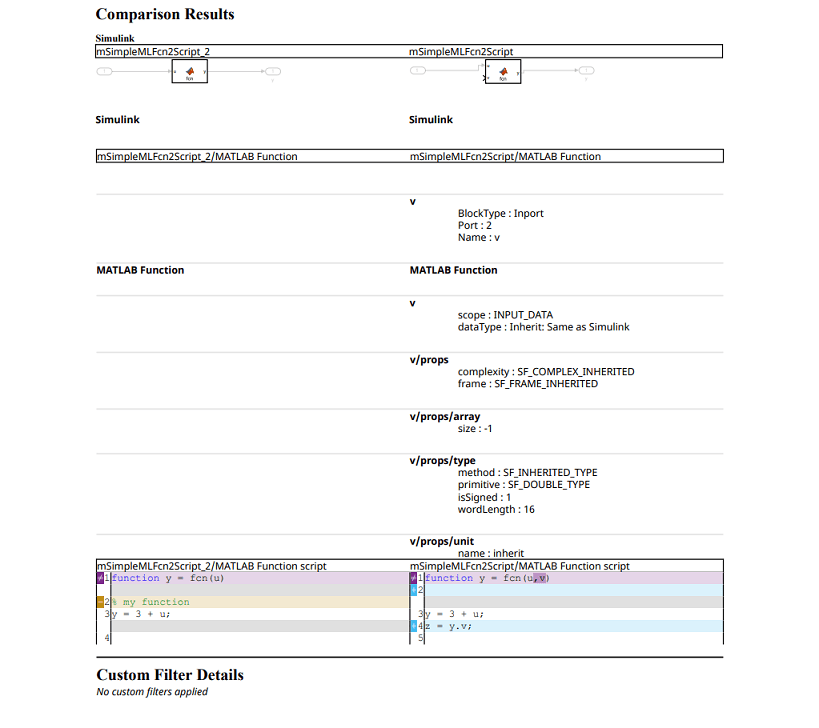
Examine Simulink model comparison results directly at MATLAB Command Window

You can now use the visdiff function to examine Simulink model comparison results directly at the Command Window. The comparison object now has a new Result property that contains information such as line-by-line comparison. For more information, see visdiff.

You can now close all currently opened comparison windows using the comparisons.closeAll command.

Compare logged signals in model files

You can now compare logged signals between two Simulink models using the Comparison Tool. When you compare models that contain logged signals, the differences appear under a Logging node in the comparison tree. You can see which logged signals were added, removed, or modified, and inspect only the parameters that changed in a focused subcomparison view.

From the comparison tree, you can filter logged signal changes using the Quick Filters pane, or highlight a logged signal directly in the Simulink Editor to locate it in your model.

Comparing logged signals in Libraries, Model References, Subsystem References, and Simscape logging is not currently supported.

Save model view settings outside model file for better source control

Starting in R2026b, Simulink saves the model view settings, such as window position, zoom level, scroll offset, and multi-monitor display, in an external JSON file in your preference directory. By saving this information outside the model file, each team member can maintain a personalized model view without affecting others. This approach enables source control to track only meaningful changes to the model, reduces merge conflicts, and streamlines collaboration when multiple users work on the same model.

To save the model view settings within the model file, set the SaveViewStateInModelFile parameter value to "on" and save the model.

set_param("modelName",SaveViewStateInModelFile="on");
save_system("modelName");

To delete the externally saved model view settings from your preference directory for deleted models, use the new Simulink.removeStaleModelViewStates function.

For more information on externally stored model view settings, see Save Model View Settings.

 Functionality being removed or changed

slxmlcomp.compare will be removed

Warns

slxmlcomp.compare will be removed in a future release. Use visdiff instead.

visdiff function hides annotations by default in Command Window report

Behavior change

Starting in R2026b, the comparison report that the visdiff function outputs at the MATLAB Command Window hides the annotation changes by default. This behavior matches the behavior of the Comparison Tool.

To restore the previous visdiff behavior in R2026b, set the default filter to match the R2024b visdiff and Comparison Tool behaviour.

s = settings();
s.comparisons.slx.DefaultFilterPath.PersonalValue = fullfile(matlabroot,"toolbox/simulink/comparisons/model/mldesktop/data/filters/R2024bDefaultFilter.json");
s.comparisons.slx.DefaultFilterName.PersonalValue = "R2024bDefaultFilter";

Data Management

 Save Simulink data dictionaries in JSON format

You can now save Simulink data dictionaries in an uncompressed JSON file. Compared to the compressed-binary format, storing a JSON data dictionary in a version control tool such as Git™ keeps the repository size more manageable and allows for using diffs in version control workflows.

Simulink serializes all sections of a text-format data dictionary into a single JSON file. Both the binary and text formats use the .sldd file extension, and existing data dictionary workflows function identically regardless of the underlying format.

By default, Simulink creates a new data dictionary in the binary format. To choose JSON as the default file format for new data dictionaries, in the Simulink Toolstrip, on the Modeling tab, select Environment > Simulink Settings. In the Simulink > Data Dictionary File pane of the Settings dialog box, set File format for new data dictionary to uncompressed text. Alternatively, set the default programmatically by using the set_param function:

set_param(0,"SLDDFileFormat","uncompressed-text")
To convert an existing binary data dictionary to JSON, in the Model Explorer Model Hierarchy pane, select the data dictionary node. Then in the Dialog pane set File Format to uncompressed-text. Alternatively, convert the data dictionary format programmatically by setting the FileFormat property of the Simulink.data.Dictionary object:

dd = Simulink.data.dictionary.open("myDictionary.sldd");
dd.FileFormat = "uncompressed-text";
saveChanges(dd);

Using standard text merge tools, such as the Git merge command, to merge JSON data dictionaries is not recommended. Instead, use the MATLAB Comparison Tool by configuring Git to call the mlMerge function for diffs and merges. For more information, see Customize External Source Control to Use MATLAB for Diff and Merge.

To compare and merge data dictionaries in Simulink, use the visdiff function to open the Comparison Tool. Use the tool to compare dictionaries regardless of format.

For more information, see What Is a Data Dictionary?

Manage model configuration sets stored in models and data dictionaries using a Simulink.data.DataConnection object

Starting in R2026b, you can manage model configuration sets in a model file or data dictionary in the same way you use the command line to interact with design data in workspaces, data dictionaries and MAT files. Create a Simulink.data.DataConnection object for the Configurations section of the data source by using the Simulink.data.connect function with the Section argument set to "Configurations". Then use the object functions to interact with the configuration sets in that section.

When using a data connection object to connect to a configuration section, keep these considerations in mind:

  • A data connection object can connect to only one section of a data source. To interact with both the Design Data and Configurations sections of a data source, create a separate connection object for each section.

  • A variable you read from a Configurations section is a copy and not a reference. To update the value of the variable in the data source, update the copy then assign the modified copy back to the data source.

  • The data connection object does not provide direct access to individual model configuration parameters. To read or change the value of a configuration parameter, use the get_param and set_param object functions.

This example demonstrates how to use a data connection object to perform some common tasks with configuration sets.

% Create connection to section in data dictionary
d1 = Simulink.data.connect("a.sldd",Section="Configurations");

% Create a new configuration set
d1.config = Simulink.ConfigSet;

% Change the value of the Solver configuration parameter
config = d1.config;
set_param(config, "Solver","ode45");

% Assign modified configuration set to the Configurations section of the data dictionary
d1.config = config;

% Change the name of the configuration set
d1.rename("config","myConfig")

For more information, see Manage Data for Simulink Models Programmatically.

Root Import Mapper: Map signal data by port name

Starting in R2026b, the Root Inport Mapper tool supports mapping signal data by port name for bus element ports. To select this map mode, in the Map Mode section of the Root Inport Mapper tool, select Port Name.
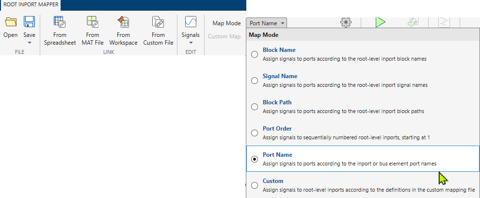
Root Inport Mapper Map Mode with Port Name mode selected.

Corresponding to this change, the mapDataToInport and getSlRootInportMap functions now support the new mapping mode option "PortName".

Signal Editor: Edit signal data faster with synchronized properties and improved performance

In R2026b, the block version of the Signal Editor tool has these changes:

  • When you change and save signal interpolation properties in the Signal Editor tool, the Signal Editor block dialog box updates with the same interpolation properties.

    Existing Signal Editor blocks do not automatically synchronize the values when opened. If you have a Signal Editor block from a model prior to R2026b, the Interpolate data and Unit parameters of the Signal Editor tool only reflect in the Signal Editor block when you edit values in the Signal Editor tool and click Save.

  • When you change and save signal units in the Signal Editor tool, the Signal Editor block dialog box updates with the same updated units.

    Existing Signal Editor blocks do not automatically synchronize the values when opened. If you have a Signal Editor block from a model prior to R2026b, the Interpolate data and Unit parameters of the Signal Editor tool only reflect in the Signal Editor block when you edit values in the Signal Editor tool and click Save.

All versions of the Signal Editor have these changes:

  • Plot data array signals with no interpolation (zero-order hold). In previous releases, the tool plotted data array signals with linear interpolation.

  • In the Inputs signal hierarchy pane, the Select all signals under same scenario option has changed to Select all signals under selected scenarios.

  • The Signal Editor tool performance is faster when viewing and editing signal data in the Signal Editor data table.

Configure one-way client-server communication for service interfaces in data dictionaries

Configure one-way client-server communication at the interface level by selecting the ServerResponseNotRequired property for service interface function elements in the Architectural Data Editor, or programmatically by setting the property to true on Simulink.dictionary.archdata.FunctionElement objects.

The function element must have no output arguments in its prototype before you can set ServerResponseNotRequired to true.

For more information about software component and architecture modeling, see Software Component Modeling.

 Functionality being removed or changed

Warning reported by default when Simulink.data.dictionary.open is unable to open a referenced dictionary

Behavior change

Starting in R2026b, when the Simulink.data.dictionary.open function is unable to open a dictionary referenced by the target dictionary, the function reports a warning, but still opens the target dictionary. The name-value argument SubdictionaryErrorAction has been removed. Previously, the function reported an error unless you called the function with the SubdictionaryErrorAction argument set to "warn".

Compiler warning for classic initialization mode

Warns

Starting in R2026b, Simulink issues a compile time warning if you use the Classic option for the Underspecified initialization detection configuration parameter. Use the Simplified option instead. For more information, see Underspecified initialization detection.

Simplified initialization mode helps to avoid unexpected simulation results and improves consistency. For more information about how to switch from classic to simplified initialization mode, see Convert from Classic to Simplified Initialization Mode.

Block Enhancements

 Simulink DateTime Blocks: Bring calendar date and time natively into Simulink models

Use Simulink DateTime blocks to run simulations at a particular real-world time, work seamlessly with date and time data, and execute time-dependent control logic. Use blocks from the DateTime library when designing satellites, modeling distributed or imperfect timekeeping systems, and scheduling logistics operations. These blocks provide:

  • The ability to specify a real-world calendar date and time at which a model is to be simulated.

  • Support for timestamps stored as integers, doubles, or fixed-point numbers.

  • Semantic support for leap seconds, leap days, Julian dates, and 12- and 24-hour clocks.

  • Support for the TAI, UTC, and TT time standards.

  • Support for loading and logging DateTime data to the MATLAB workspace as MATLAB datetime data.

Simulink DateTime includes these blocks:

To define the reference calendar date and time for a model, see Date and time at simulation time zero.

To create DateTime data types, use the Simulink.DateTimeType object.

To log DateTime data, use signal logging, the Outport block, the Record block, or the To Workspace block.

Starting in R2026b, these blocks support DateTime data types:

In the Simulation Data Inspector, DateTime signals appear as a numeric representation of the underlying DateTime data.

 Conditionally hold signal values using the new Conditional Hold block

The new Conditional Hold block conditionally holds its input signal u based on the value of the Boolean condition signal, h. If the input is a vector, the block holds all elements of the vector.

The block accepts an initial condition, which it uses only at the first time step, when the hold value condition is true and the block has no previous input to hold. Use this block to simplify a common modeling pattern where you might have used multiple blocks.

Enhancements in Scope and Floating Scope

Display measurements data using engineering notation

The Scope, Floating Scope and Scope Viewer display the cursor measurements, peaks, statistics, and bilevel measurements using engineering notation.

Note

The Signal Statistics panel, Peaks panel, and the bilevel measurements panel require a DSP System Toolbox™ or Simscape™ license.
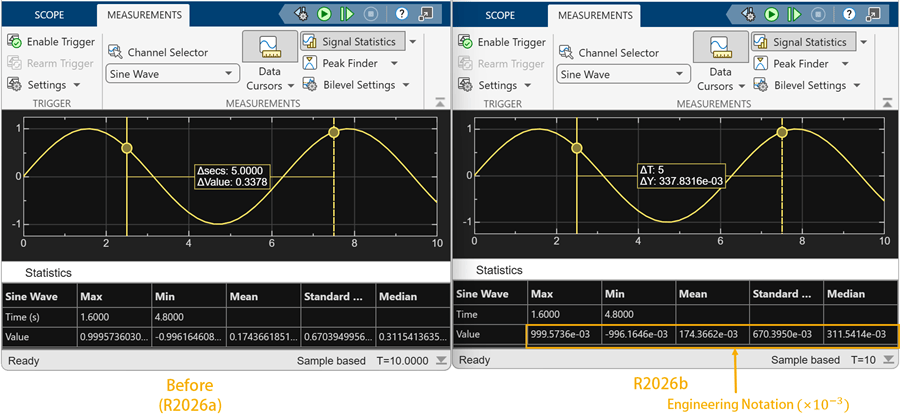
Sinusoidal signal showing cursors and signal statistics. The scope displays the measurements data using the power of 3 in engineering notation.

Access style settings from context menu

You can now also access the style settings of the Scope, Floating Scope and Scope Viewer by right-clicking the scope display and selecting Style.

Support for calendar date and time

You can now visualize the simulation data and the measurements data in Scope, Floating Scope and Scope Viewer using the real-world calendar date and time. For more information on how to enable this support, see the Enable DateTime on T-Axis parameter description in the scope reference page.

New Video: Visualize simulation results with Simulink scopes

Learn how to effectively visualize signal data to explore signal behavior and troubleshoot simulations using the Scope block and Floating Scope in Simulink. In this video, you will learn how to:

  • Add and manage Scopes and Scope Viewers

  • View signal data without cluttering your model

  • Customize scope displays

  • Utilize measurement tools

  • Dock multiple scopes in one window

Here are the links to the video on:

 Signal Editor block: Default signal property source changed to MAT file

Starting in R2026b, the default value of the Use properties from parameter of the Signal Editor block is Signal data in MAT file. In releases before R2026b, the default value was Dialog parameters.

Sqrt block updates

The Sqrt block now supports a Lookup method for the sqrt function. Use the Lookup method if you want a fast, approximate calculation with less resource usage and near floating-point accuracy. Selecting this Lookup method enables the Number of data points parameter, where you can specify the number of data points for the lookup table.

Starting in R2026b, you can use these programmatic parameters to set the Method parameter. Existing models continue to work.

  • SqrtAlgorithmType — For the sqrt function, which includes the Exact and Lookup methods.

  • RsqrtAlgorithmType — For the rsqrt, which includes the Exact and Newton-Raphson methods.

Saturation Block: Output saturation status through new ports block updates

You can enable saturation status ports on the Saturation block by selecting the new Output saturation status parameter.

Blockset Designer: Streamlined editing with context menus and integrated messages

Starting in R2026b, the Blockset Designer has these changes:

  • Error and warning messages are now integrated into the Blockset Designer interface. They no longer appear in separate windows.

  • For the creation of blocks or sublibraries, Blockset Designer now allows you to create the block or sublibrary inline. In previous releases, a dialog box appeared for this operation.

  • For the renaming of library blocks or sublibraries, Blockset Designer allows you to edit the library block or sublibrary name inline. In previous releases, a dialog box appeared for this operation.

Selector and Assignment block updates

Starting in R2026b, by default, the Selector and Assignment blocks check for out-of-range index values in accelerator and rapid accelerator simulation modes. The Check for out-of-range index in accelerated simulation parameter is no longer available to disable these checks. This change enables the blocks to always perform correct and necessary run-time out-of-range index checking.

You can still turn off these checks by programmatically setting the RuntimeRangeChecks property on the Selector or Assignment block. However, if you turn off the check for out-of-range index values in accelerator and rapid accelerator simulation modes, the next time you open the block, the Check for out-of-range index in accelerated simulation parameter appears with a warning.

In previous releases, you used the block dialog Check for out-of-range index in accelerated simulation parameter or RuntimeRangeChecks property to control the check.

Steady State Detection block: Detect when systems reach steady-state operation during simulation

To detect when systems reach steady-state operation during simulation, use the new Steady State Detection block in the Simulink Extras library. The block produces a Boolean output you can use to trigger downstream logic, such as stopping the simulation to save an operating point or switching control logic. The block can detect steady-state operation based on both constant and periodic input signals.

Block parameters define the criteria for steady-state operation as a target, tolerance, and stability window. By default, the block automatically detects the target value or amplitude and period.

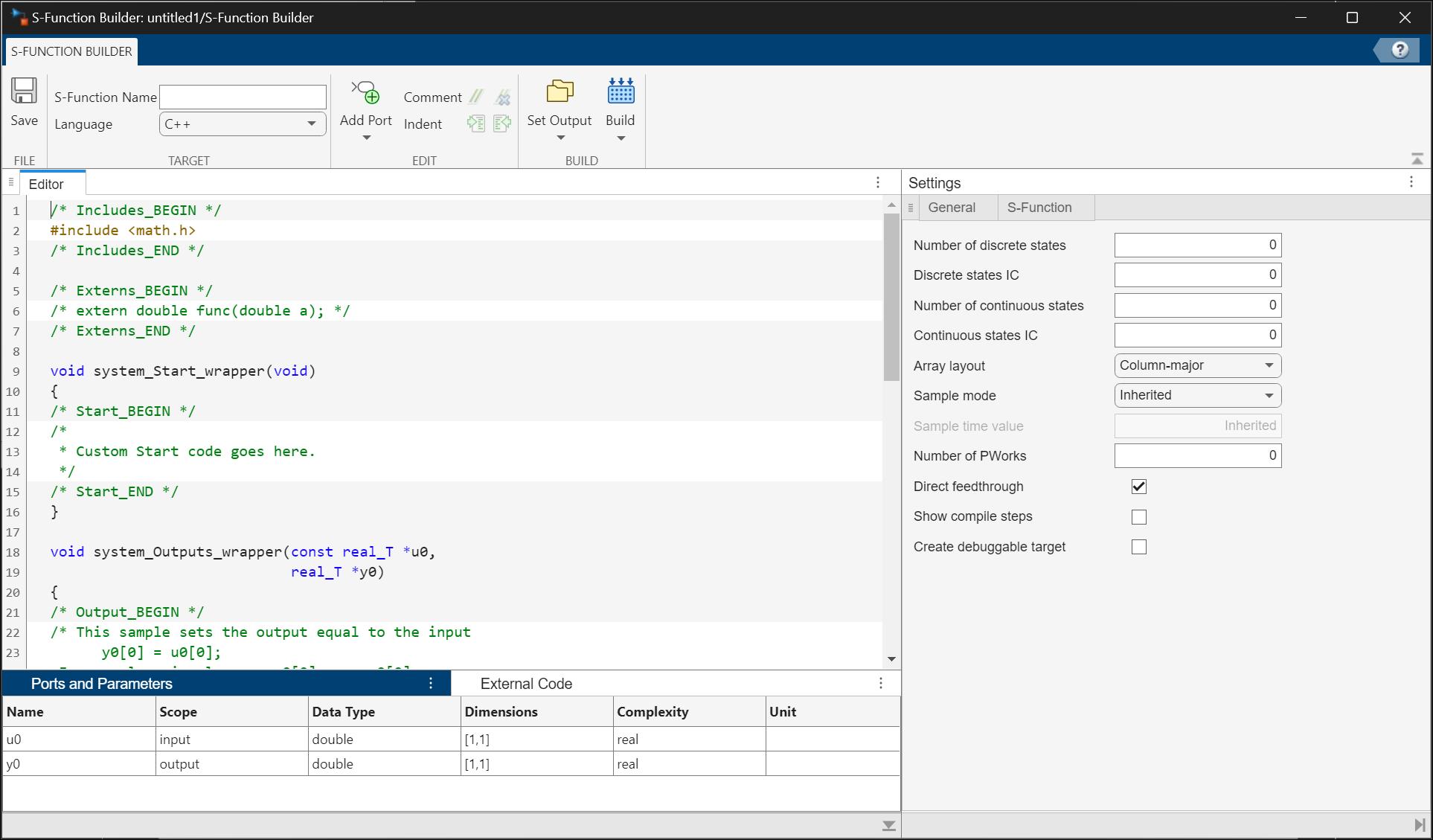
C Function block: New block editor

Starting in R2026b, a new C Function block editor is introduced that comes with modern capabilities such as syntax highlighting, auto-indentation, and symbol highlighting. The editor also supports both light and dark themes, and the MATLAB desktop theme determines its appearance.

C Function block: Specify custom code dependencies programmatically

Starting in R2026b, you can specify dependencies for custom C/C++ code in the C Function block using the UpdateBuildInfo option of the Custom Code Location parameter. The dependencies include header files, source files, libraries, directories, compiler flags, macro definitions, and linker flags for the compiler. This enhancement allows you to programmatically specify custom code dependencies in a C Function block for both simulation and code generation purposes.

Display images based on signal values using a customizable MultiStateImage block

You can now display images based on signal values using the new MultiStateImage block from the Customizable Blocks library. The MultiStateImage block pairs state images you provide with state values or ranges of values that you specify. When the value of the connected signal matches a state value or falls within a state value range, the MultiStateImage block displays the corresponding state image.

The block is a more customizable version of the MultiStateImage block from the Dashboard library. With the MultiStateImage block from the Customizable Blocks library, you can:

  • Specify state values as discrete values or ranges.

  • Configure each state individually, or apply the default state settings to all states.

  • Set the position and size of each state image individually.

  • Resize the state images freely by dragging their corners.

  • Add a foreground image, background image, or background color to the block.

View multidimensional signals with Display block

The Display block from the Customizable Blocks library can now display multidimensional signals. Previously, the block could only display scalar signals.

By default, the block displays multidimensional signals in a grid. To set the color of the grid lines, select the block. In the Property Inspector, on the Design tab, in the Text component, select a new color for Grid Color. To turn the grid off, in the same location, toggle the Show grid for non-scalar signals button off.

A Display block displays the value of the signal line connected to a Constant block. The Constant block value is the matrix [5 8; 9 4]. The Display block displays the element values in a grid with green lines.

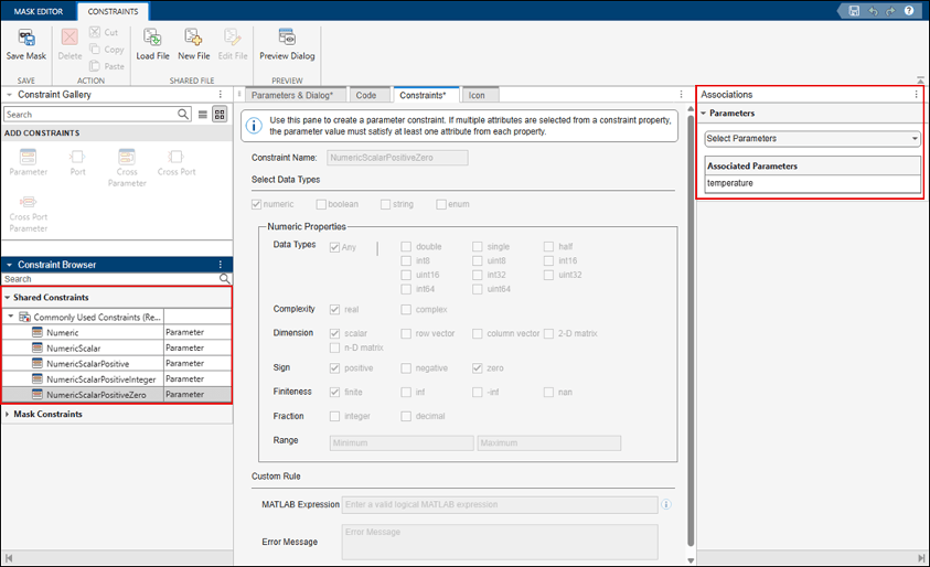
Set port constraints of masked blocks to accept all numeric data types

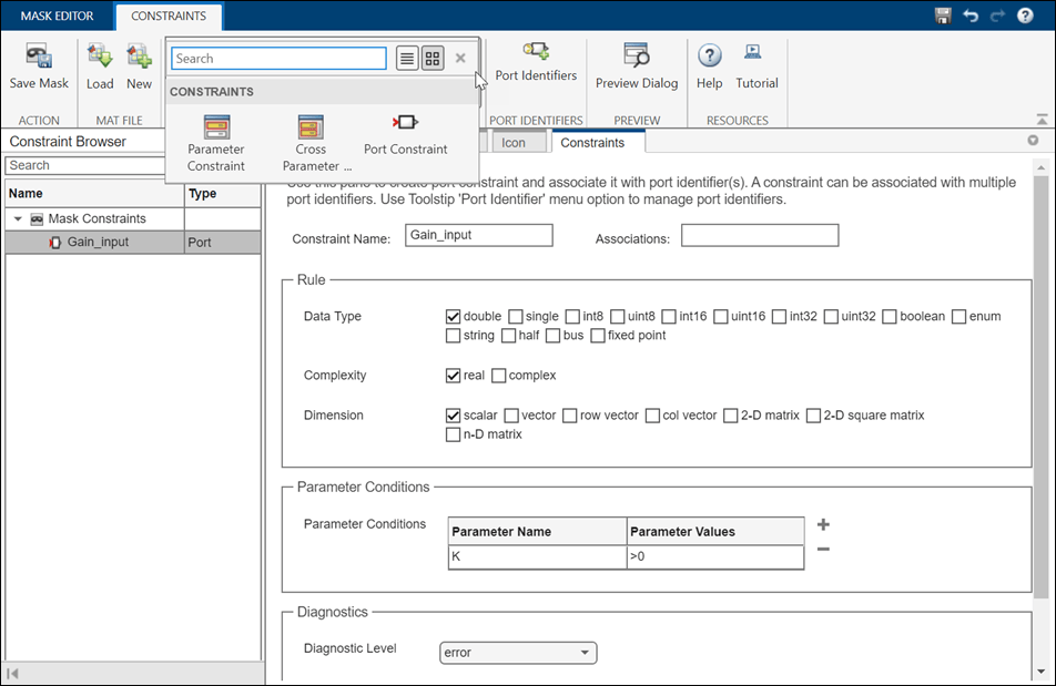
Starting in R2026b, you can enable masked blocks to accept any numeric data type by setting the value of the Rule.DataType property of the port constraint to numeric. Previously, to use all numeric data types, you had to specify each numeric type individually when defining a port constraint. For more information, see addPortConstraint.

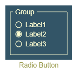
Evaluate only custom values in Combo Box parameters of masked blocks

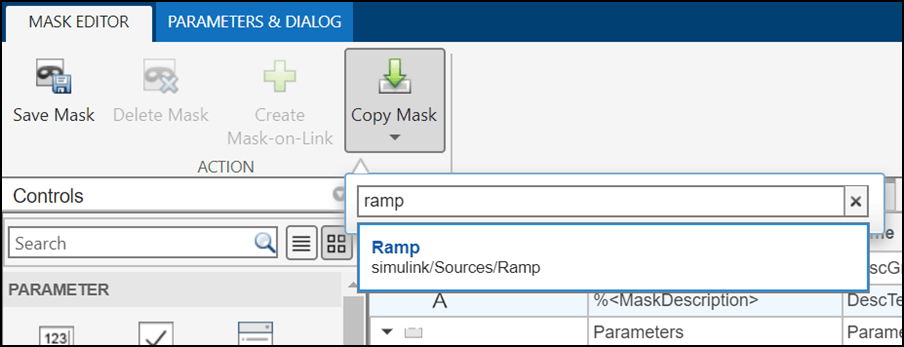
When you enable the Evaluate attribute for a combobox mask parameter, Simulink evaluates both predefined and user‑defined values as MATLAB expressions. Starting in R2026b, you can set a combobox mask parameter to evaluate only the custom values you enter.

You can enable the Evaluate only custom values option of a combobox parameter in the Behavior section of the Property Editor pane in the Mask Editor.
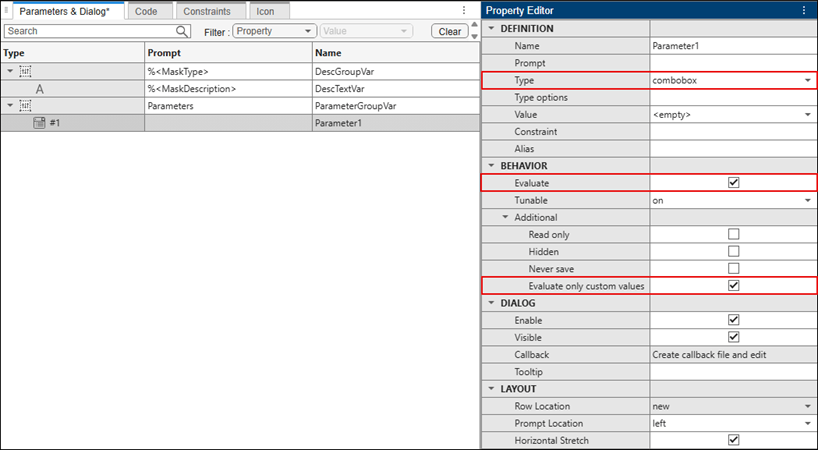
Mask Editor showing a parameter selected in the Parameters pane. In the Property Editor section, the Type is set to combobox and Evaluate only custom values is enabled.

To enable the Evaluate only custom values option from the command line, see Simulink.MaskParameter.Behavior.

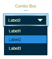
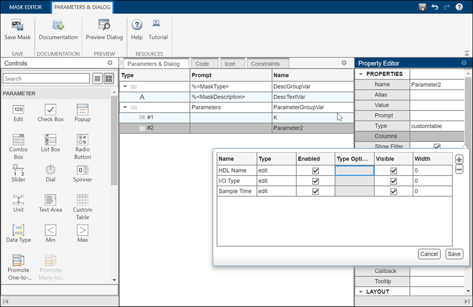
Use combo box in Custom Table parameters of masked blocks

Starting in R2026b, you can set the column type in a custom table parameter to combobox from the Mask Editor or programmatically. To set the column type in the Mask Editor, in the Property Editor pane, click Columns, and then set Type to combobox.
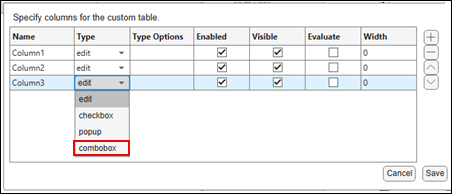
Custom Table column settings dialog showing the Type field set to combobox for a column, with other column properties listed in a table.

To add a combo box column from the command line, see Control Custom Table Parameter Programmatically.

Custom Table parameter callback is optimized

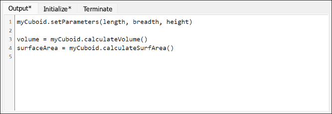
Starting in R2026b, callbacks for custom table mask parameters run only when parameter values change. This change reduces unnecessary callback execution and matches the behavior of other mask parameters.

Parameter Writer Block Support for workspace variables or mask parameters used by Simscape Blocks

Starting in R2026b, you can use the Parameter Writer block to write to base workspace variables, model workspace variables, mask parameters, and Simulink data dictionary variables used by the run-time parameters of Simscape blocks. This capability expands the scope of the Parameter Writer block beyond Simulink blocks. For more information about Simscape run-time parameters, see About Simscape Run-Time Parameters (Simscape).

Improved performance of multi-instance MATLAB System block simulation and code generation

In R2026b, simulation and code generation are faster for models with multiple instances of MATLAB System blocks. In rapid accelerator mode, simulation performance can scale more efficiently as you add instances of MATLAB System blocks because Simulink utilizes code reuse when possible. Code generation performance has also been improved for rapid accelerator, GRT, and ERT workflows through more effective reuse of shared inference results.

Propagate sample rates from FMU ports to connected blocks

Starting in R2026b, sample rates of FMI 3.0 FMUs can propagate from individual FMU ports to connected upstream and downstream blocks based on FMI periodic clock dependencies. This capability allows connected blocks to run at more appropriate rates, which can improve simulation performance, particularly in large models.

This capability is supported for both Model Exchange and Co‑Simulation FMUs when clock‑based sample rate propagation is enabled.

Icon Editor: Add dynamic text, position elements relatively, and inherit domain styles

Starting in R2026b, Icon Editor has these enhancements:

  • Add dynamic text — Add expression text on a masked block icon by using the Expression Text element from the Tools pane. To edit an expression, double-click the Expression Text element on the canvas and write a JavaScript® expression such as "Gain value is " + parameterName. To customize expression behavior, use the options in Expression Text section in the Element Properties pane.

    For more information, see Display Text Dynamically on Block Icon Based on Parameter Values.
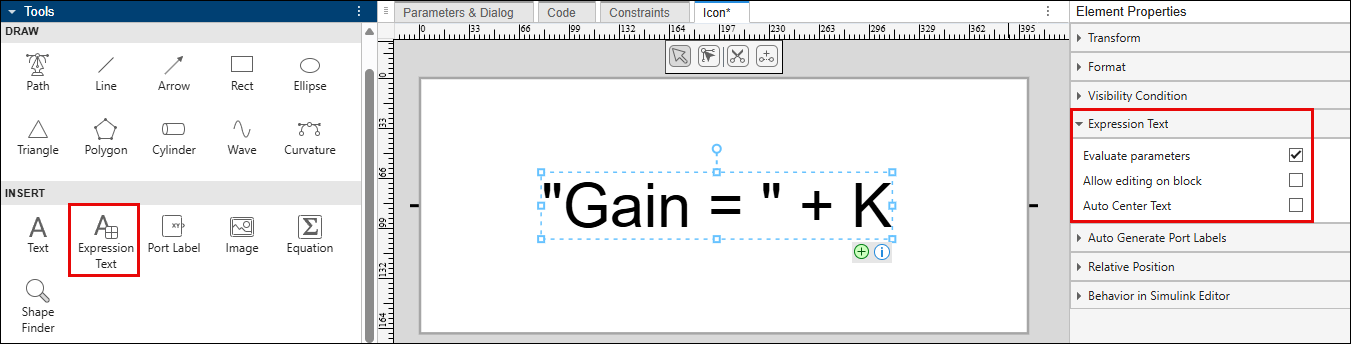
    expression-text

  • Position an icon element relative to another element — The updated Relative Position section in the Element Properties pane now makes it easier to position an element relative to another element or the canvas.

    For more information, see Position Elements Relatively Using Relative Positioning.
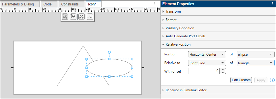
    relative-position-example

  • Inherit domain styles for Simscape block icons — You can now make Simscape block icons inherit port domain styles by using the Inherit Styles option in the Format section. For example, to inherit a style based on a right-side port and the electrical domain for a Variable Resistor block, you would set Inherit Styles to R0: Electrical. Previously, domain styles could be inherited only by using the Port Binding option in the toolstrip.

  • Display port labels on masked block icons — You can now display port labels from the blocks inside the mask directly on masked block icons by selecting the Show port labels from block check box in the Icon Settings section.

View and edit notes for Simulink referenced models and subsystems

Starting in R2026b, you can view and edit notes associated with referenced models and subsystems directly from their corresponding blocks in the parent model.

 Functionality being removed or changed

Previous versions of lookup table blocks permanently removed

Previous versions of these lookup table blocks are removed in R2026b. Use the listed replacement blocks instead.

Previous BlockReplacement Block

PreLookup Index Search

Prelookup

Interpolation (n-D) Using PreLookup

Interpolation Using Prelookup

When you load a model that contains the PreLookup Index Search or Interpolation (n-D) Using PreLookup blocks, Simulink automatically replaces these blocks with the Prelookup and Interpolation Using Prelookup blocks.

  • If the PreLookup Index Search and Interpolation (n-D) Using PreLookup blocks were directly connected, the automatic replacement should have no issues.

  • If the PreLookup Index Search and Interpolation (n-D) Using PreLookup blocks were not directly connected, when the blocks are loaded or the model is compiled, Simulink checks for incompatible signal lines and other compatibility issues. When prompted, click suggested fix-it actions.

When you resave the model, the model is saved with the new blocks.

Lookup Table Dynamic block to be removed

Behavior change in future release

The Lookup Table Dynamic block will be removed in a future release. Use the 1-D Lookup Table block with the Table data or Breakpoints > Source parameters set to Input port instead.

Lookup Table and Lookup Table (2-D) blocks to be removed

Behavior change in future release

The Lookup Table and Lookup Table (2-D) blocks will be removed in a future release. Use the replacement blocks listed in the table instead. For more information, see Update Lookup Table Blocks to New Versions.

Current BlockReplacement Block

Lookup Table

1-D Lookup Table

Lookup Table (2-D)

2-D Lookup Table

These blocks are compatible with the replacement blocks.

Selector and Assignment block out-of-range check behavior change

Behavior change

Starting in R2026b, the Selector and Assignment blocks check for out-of-range index values in accelerator and rapid accelerator simulation modes by default. The dialog box Check for out-of-range index in accelerated simulation parameter for the Selector and Assignment blocks is now hidden and can only be programmatically enabled by using the RuntimeRangeChecks property.

If you load an existing model with these checks turned off, a warning appears stating that the .setting is not recommended. The model continues to run.

Signal Editor block default change

Behavior change

Starting in R2026b, the default value of the Use properties from parameter of the Signal Editor block is now Signal data in MAT file. In releases before R2026b, the default value was Dialog parameters. Starting in R2026b, the Interpolate data, Unit, Apply signal properties to all scenarios and Apply signal properties to all signals are read-only by default. If you have applications that set these values programmatically using the SignalPropertySource property, the application might now return an error.

To modify the Interpolate data and Unit settings of signals, take one of these actions:

  • From the Signal Editor block, start the Signal Editor tool and modify the signal properties in that interface.

  • Load the MAT file associated with the Signal Editor into the workspace, modify the data, and save the data back to the MAT file.

  • Set Use properties from back to Dialog parameters to override the data settings with the Interpolate data and Unit parameter values.

Signal Builder block warning

Starting in R2026b, adding the Signal Builder block to a model returns a warning.

Connection to Hardware

Support for PWM and ADC interrupts on Teensy boards

The new PWM and Analog Input blocks for Teensy 4.0 and 4.1 boards enable hardware PWM and ADC interrupts.

The PWM block supports hardware timer-based interrupts, including:

  • PWM overflow interrupts

  • Compare-match interrupts

These interrupts allow the model to respond precisely to PWM timer events supporting timer-critical control and synchronization scenarios.

The Analog Input block supports end-of-conversion (EOC) interrupts. EOC interrupts let the model execute application logic immediately after an analog-to-digital conversion completes, improving responsiveness and timing accuracy.

You can attach interrupt handlers using the Hardware Interrupt block and execute control algorithms from interrupt service routines. These blocks require Embedded Coder.

For applications that use these blocks, see Open-Loop Control to Sensorless FOC of PMSM on Teensy Hardware.

Support for fast serial logging on Arduino boards

Simulink Support Package for Arduino® Hardware now supports frame-based serial logging support to the Serial Transmit block. Frame-based logging improves data logging reliability when the transmit rate of the target model is higher than the receive rate of the host model.

The Serial Transmit block includes a new Enable frame size parameter. When you enable this option, the block exposes a Frame size parameter that lets you specify the number of data samples to package and transmit as a single frame. This framing approach helps make serial data transfers robust and efficient for high-rate control and logging applications where conventional serial logging or external mode over serial is not suitable.

For applications that use frame-based serial logging for high-rate motor control data visualization, see Open-Loop Control to Sensorless FOC of PMSM on Teensy Hardware.

Motor control series for PMSM using Teensy hardware: Reference Examples

The support package includes a new series of reference examples that show how to implement sensorless field-oriented control (FOC) of a permanent magnet synchronous motor (PMSM) using a Teensy development board and a DRV8305EVM inverter. The series progressively builds motor control concepts from basic open-loop operation to advanced closed-loop sensorless FOC. These examples use the new PWM and Analog Input blocks with Hardware Interrupt support and frame-based serial logging.

Support for MAT-file logging on Teensy boards

Simulink Support Package for Arduino Hardware now supports logging data directly to MAT files on SD cards when using Teensy 4.0 and 4.1 hardware. Recording MAT files on your target hardware lets you analyze data in Simulink without manual file conversion.

The support package adds new configuration options for MAT-file logging when you select Teensy 4.0 (arduino Compatible) or Teensy 4.1 (arduino Compatible) options in the Configuration Parameters dialog box.

  • For Teensy 4.0 boards, you can log data using an external SD card module connected through a serial peripheral interface (SPI).

  • For Teensy 4.1 boards, you can log data using the on-board SD card interface or an external SD card module connected through an SPI.

To enable MAT-file logging, in the model configuration parameters, in the Hardware Implementation pane, set Hardware board to your Teensy board. Then, in the Code Generation pane, go to Interface and expand Advanced parameters and select MAT-file logging. For more information, see Working with Arduino SD Card File Read Blocks.

Support for XCP over CAN on Arduino boards

You can now use XCP over CAN for external mode monitoring and calibrating with these boards.

  • Arduino Due

  • Teensy 4.0 and 4.1

  • Arduino Uno R4 Wi-Fi® and Minima

  • Arduino Nano R4

This capability allows you to tune parameters, monitor signals over CAN, and generate A2L files for use with third-party calibration tools from vendors such as Vector, Kvaser, PEAK-System, and NI™ (NI-XNET).

Using XCP over CAN requires Vehicle Network Toolbox™ and supported external CAN hardware. For more information, see Set Up, Deploy, and Calibrate Arduino Application Using XCP on CAN, Generate A2L File for Third-Party Calibration Tools Using XCP on CAN Host Communication, and External mode.

Support for variable length UDP payloads and blocking receive mode on Arduino

The WiFi UDP Send and WiFi UDP Receive blocks now support variable-length UDP payloads, enabling models to transmit and receive data whose size changes at run time. Previously, these blocks supported only fixed-length data exchange.

Additionally, the WiFi UDP Receive block now supports blocking and non-blocking modes. These modes control block behavior when no packet is available.

  • Blocking mode — Wait for incoming data up to a specified timeout.

  • Non-blocking mode — Do not wait.

The new Status port indicates whether data was received, unavailable, or if a timeout occurred.

Processor-in-the-loop support for Raspberry Pi Pico and ESP32 boards

This release adds PIL support for the following Arduino-compatible boards:

  • Raspberry Pi® Pico

  • Raspberry Pi Pico W

  • ESP32-WROOM

  • ESP32-WROVER

  • ESP32-S3 series

You can now use PIL with these boards to verify target-specific code behavior, perform execution-time profiling, and evaluate algorithm performance before deployment. For more information, see Code Verification and Validation with PIL on Arduino Hardware.

Support for Arduino Nano R4 board

You can now use Simulink Support Package for Arduino Hardware to design, run, and deploy models to the Arduino Nano R4 board.

To use this board, in the model configuration parameters, in the Hardware Implementation pane, set Hardware board to Arduino Nano R4. For more information, see Supported Arduino and Arduino Compatible Hardware — Simulink Support Package for Arduino Hardware.

Support added for Arduino compatible ESP32-S3 board

You can now use Simulink Support Package for Arduino Hardware to design, run, and deploy models to these ESP32-S3 modules and boards:

ModuleBoard

ESP32-S3-WROOM-1/1U

ESP32-S3-DevKitC-1

ESP32-S3-WROOM-2/2U

ESP32-S3-DevKitC-1

ESP32-S3-MINI-1/1U

ESP32-S3-DevKitM-1

To use these modules and boards, in the model configuration parameters, in the Hardware Implementation pane, set Hardware board to ESP32-S3 Series (Arduino Compatible). Then, in the Target hardware resources, select ESP32-S3 board properties to select the target board and its supported module or development kit variant.

Support for Arduino Nano ESP32 board

You can now use Simulink Support Package for Arduino Hardware to design, run, and deploy models on Arduino Nano ESP32 boards.

To use this board, in the model configuration parameters, in the Hardware Implementation pane, set Hardware board to Arduino Nano ESP32. For more information, see Supported Arduino and Arduino Compatible Hardware — Simulink Support Package for Arduino Hardware.

MATLAB Function Blocks

Code generation for more toolbox functions

In R2026b, you can generate code for additional toolbox functions and objects. For a list of all functions and objects that are supported for code generation, see:

These are links to the release notes of some toolboxes that added code generation support in R2026b:

Image Processing Toolbox

See C Code Generation: Generate code from additional functions using MATLAB Coder (Image Processing Toolbox).

Statistics and Machine Learning Toolbox

See Generate C/C++ code for prediction using a custom neural network architecture (requires MATLAB Coder and Deep Learning Toolbox) (Statistics and Machine Learning Toolbox).

Wavelet Toolbox

See Deep Learning: Code generation for discrete wavelet transform (Wavelet Toolbox).

Modeling Guidelines

Modified modeling guidelines

Starting in R2026b, the following changes apply to the modeling guidelines.

R2026a

New Features, Bug Fixes, Compatibility Considerations

 New Simulink context menus prioritize frequently used functionality

In R2026a, the context menus that appear when you right-click the Simulink model canvas or model elements such as blocks, signal lines, and annotations are changing. This image shows the differences between the context menu that opens when you right-click a Constant block in R2025b and the context menu that opens when you right-click the same block in R2026a.
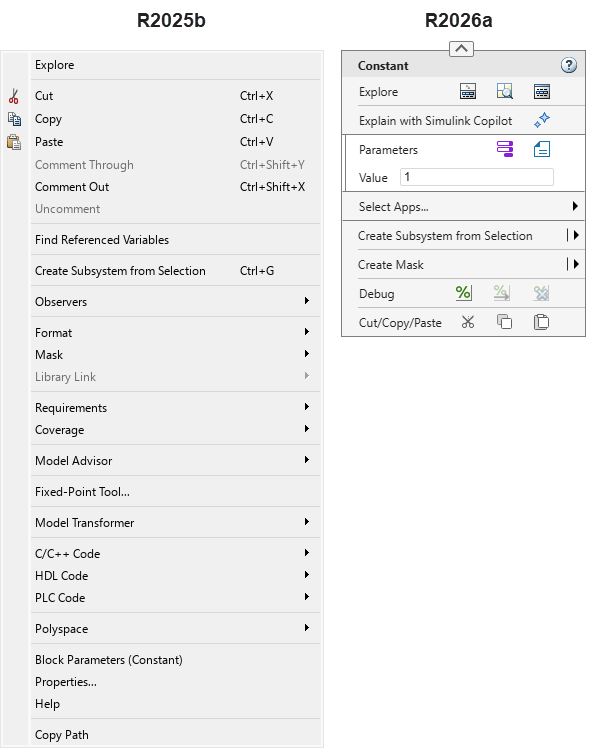
On the left is the context menu that opens when you right-click a Constant block in R2025b, and on the right is the same menu in R2026a. The R2026a context menu is more compact than the R2025b context menu and contains buttons, clickable text options, and a text box.

In addition to conventional menu items, the R2026a context menu design includes interactive elements such as buttons, text boxes, radio buttons, check boxes, and drop-down lists. To view a tooltip that describes the action you can take by pressing a button, pause your pointer on the button icon.
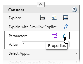
The Constant block context menu is open, and a pointer is paused on the Properties button. A tooltip displays Properties.

This table lists some of the common buttons in the context menus of blocks.

ButtonTooltip
Model Data Editor buttonModel Data Editor
Referenced Variables buttonReferenced Variables
Open in Model Explorer buttonOpen in Model Explorer
Explain with Simulink Copilot buttonExplain with Simulink Copilot
Block Parameters buttonBlock Parameters
Properties buttonProperties
Comment Out buttonComment out the block.
Comment Through buttonComment through the block.
Uncomment buttonUncomment the block.
Cut buttonCut
Copy buttonCopy
Paste buttonPaste

For a tooltip showing a list of all the actions that you can take by pressing the buttons in a button row, click the name of the button row. For each button, the tooltip shows the button icon followed by a description of the button action. When there is only one button in a button row, clicking the name of the button row presses the button instead of opening a tooltip.
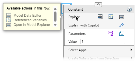
The Constant block context menu is open, and a pointer is paused on the Explore button row. A tooltip displays "Available actions in this row: Model Data Editor, Referenced Variables, Open in Model Explorer". Each option the tooltip displays is preceded by the corresponding button icon.

To open the help documentation, in the upper right corner of the context menu, click the Open help documentation button .

You can find formatting options in the format bar, for example, options to change fonts and colors, show or hide block names, show or hide the content preview of a subsystem, and auto-arrange the model. You can also find clipboard options such as copy and paste there. To expand or collapse the format bar, click the arrow button at the top of the context menu.

The Constant block context menu is open and the format bar is expanded.

You can set the values of certain parameters and properties directly in the context menu using text boxes, radio buttons, check boxes, and drop-down lists. For example, to set the value of a Constant block, right-click the block, and in the Value box, enter the new value.
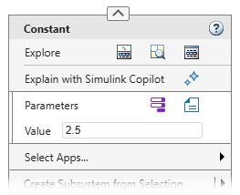
The Constant block context menu is open, and in the text box labeled Value, the value 2.5 is entered.

To add information overlays such as units or execution order to a model, right-click the model canvas and pause your pointer on Information Overlays. Then, select an overlay option.
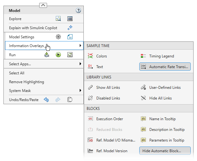
Top Model context menu with Information Overlays gallery expanded

In R2025b, you could access options that belong to an app such as the HDL Coder™ app or the Polyspace® Code Verifier app through menu items such as HDL Code or Polyspace. In R2026a, app-specific options are located in app sections. App sections are not shown by default. To access app-specific options, you must add the relevant app section to the context menu.

For example, this image highlights the options in the R2025b Constant block context menu that you can access in R2026a by adding app sections.
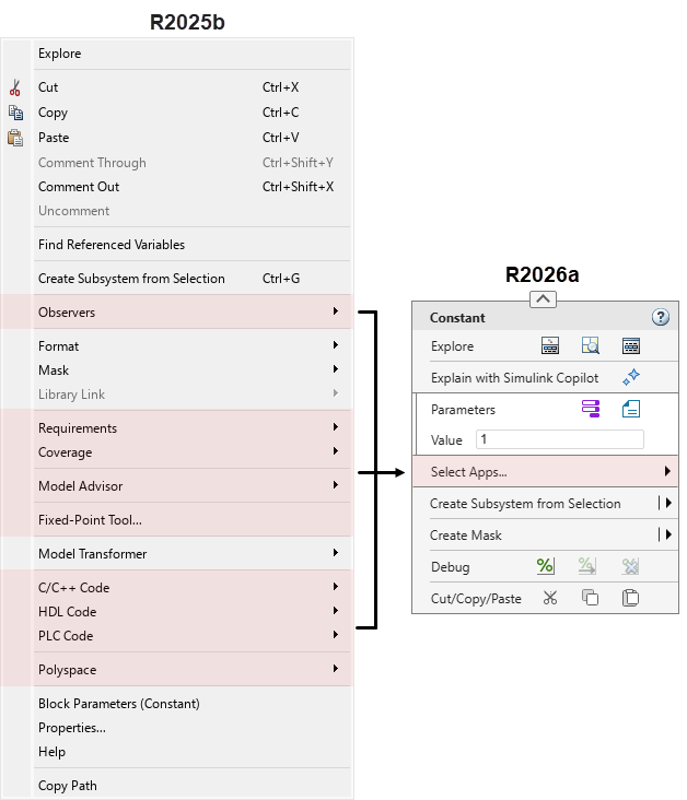
The context menu that opens when you right-click a Constant block in R2025b (left) and R2026a (right), with the options belonging to apps highlighted in the R2025b version of the menu, and the Select Apps row highlighted in the R2026a version of the menu

To add an app section to the context menu, pause your pointer on Select Apps, and then select the app. When you add an app section, the same app windows and toolstrip tabs open as when you click the app icon on the Apps tab in the Simulink Toolstrip. Alternatively, open the app from the Simulink Toolstrip. When you open an app, the corresponding app section appears in the context menu.

A pointer right-clicks the model canvas. The Top Model context menu appears. The pointer pauses on Select Apps, then on HDL Coder. In the context menu, a new section containing options specific to HDL Coder appears. The section outline flashes yellow three times.

If you are unsure whether a menu option you use is part of an app, or you know the option is part of an app but are unsure of which app, check this table. The table lists the apps associated with some of the most common R2025b context menu items.

R2025b Context Menu ItemApp
C/C++ CodeEmbedded Coder button Embedded Coder
Flip Simulink Coder button Simulink Coder
CoverageCoverage Analyzer button Coverage Analyzer
Design VerifierDesign Verifier button Design Verifier
Fixed-Point ToolFixed-Point Tool button Fixed-Point Tool
HDL Code

HDL Coder button HDL Coder

Identify Modeling ClonesClone Detector button Clone Detector
Linear Analysis PointsLinearization Manager button Linearization Manager
Metrics DashboardThe options for this app are no longer available in the context menu.
Model AdvisorModel Advisor button Model Advisor
Model SlicerModel Slicer button Model Slicer
Model TransformerThe options for this app are no longer available in the context menu.
ObserversSimulink Test button Simulink Test
PLC CodePLC Coder button PLC Coder
Polyspace

Polyspace Code Verifier button Polyspace Code Verifier

Requirements or Requirements at This LevelRequirements Manager button Requirements Manager
Requirements Viewer button Requirements Viewer
Test Harness

Simulink Test button Simulink Test

You can add multiple app sections. To add another app section, pause your pointer on Select Apps again, and select a different app.

In the model in which you add an app section, the app section appears in all context menus and persists across Simulink sessions. For example, if you right-click a block and add an app section, and then right-click a signal line in the same model, the signal line context menu also shows the app section you added. However, if you open a context menu in a different model, the context menu does not show the app section. If you open a context menu when none of the actions of an app section are available, the context menu might not show the app section.

To collapse an app section, click the down arrow button in the upper left of the app section. To expand the app menu section, click the arrow again.

To remove an app section from the context menu, pause your pointer on the app icon at the left edge of the app-specific section and click Close App. Alternatively, pause your pointer on Select Apps, and then cancel the app selection. You can also collapse the app section and then click the X on the right.

In addition to adding and removing app sections, you can also customize the context menus with the new design by adding widgets or disabling widget actions. For information, see Customize Simulink Context Menu Using Extension Points.

For lookup tables showing how you can access R2025b context menu options in R2026a, see Find Simulink Context Menu Options. The tables cover the options in the context menus of Constant blocks, top level models, signal lines, and text annotations. For a list of options that are no longer available in the Simulink context menus going forward, see Options that have been removed from Simulink context menus.

Move blocks in and out of subsystems using Simulink Toolstrip

Starting in R2026a, when you select multiple blocks on the Simulink canvas, you can use the Move In and Move Out buttons on the Simulink Toolstrip to move the blocks into or out of a subsystem. If the selected blocks are connected to a subsystem, use the Move In button to move the blocks into the subsystem. If the selected blocks are inside a subsystem, use the Move Out button to move the blocks up one level from the subsystem. This allows you to reorganize the model while preserving signal connections and block properties after refactoring. This feature eliminates the need to manually move blocks in or out of the subsystem when required.

The Move In and Move Out buttons appear in the Move section of the Multiple tab of the Simulink Toolstrip. Alternatively, you can use the context menu for move operations. Right-click the selected blocks and select Move > Move In to move blocks into a subsystem, or Move > Move Out to move blocks up one level. You can undo (Ctrl+Z) and redo (Ctrl+Y) the move operation to reverse or restore any changes.

For more information, see Move Blocks Into and Out of Subsystems.
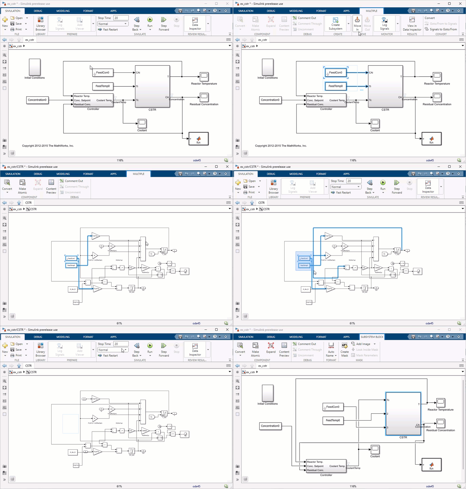
Animated image. In the image, there is a subsystem called CSTR. A Constant block named FeedTemp0 and a masked subsystem named FeedCon0 are connected to this subsystem. The pointer selects both the Constant block and the masked subsystem. The Multiple tab appears in the toolstrip. In the Multiple tab, the pointer clicks the Move In button, moving the two blocks into the CSTR subsystem. Next, the pointer selects the Constant block and masked subsystem again. In the Multiple tab, the pointer clicks the Move Out button, moving the two blocks out of the CSTR subsystem.

The Simulink Environment: Self-paced, interactive course available as part of Online Training Suite subscription

The Simulink Environment is a new course that teaches you to:

  • Use block diagrams and MATLAB code to model and simulate algorithms.

  • Configure how models run using callbacks.

  • Visualize simulation outcomes.

  • Manage simulation data and exchange data with Simulink.

For more information, see The Simulink Environment.

Model Dynamic Systems: Self-paced, interactive course available as part of Online Training Suite subscription

Model Dynamic Systems is a new course that teaches you to:

  • Model continuous and discrete dynamic systems from mathematical models using differential and difference equations, transfer functions, and state-space representations.

  • Represent physical boundaries and multiple sample rates.

For more information, see Model Dynamic Systems.

Access course readings, videos, and quizzes without product licenses

You can now open a course even if you do not have licenses for all products used by the course. Learning activities such as readings, videos, and quizzes no longer require a product license. To open a Simulink exercise, you must have licenses for all products used by the exercise.

For more information, see Simulink Online Courses.

Save copy of model from the Simulink Editor

You can now save a copy of your model from the Simulink Editor. On the Simulation tab, select Save > Save Copy As. When you use this option, Simulink saves the copy of the file in the specified folder, but it does not replace the model in your current session.

Simulink Preferences has been renamed Simulink Settings

Simulink Preferences has been renamed Simulink Settings. Use Simulink Settings to specify Simulink editing environment options and default behaviors. To open Simulink Settings, in the Simulink Toolstrip, on the Modeling tab, in the Evaluate and Manage section, select Environment > Simulink Settings.
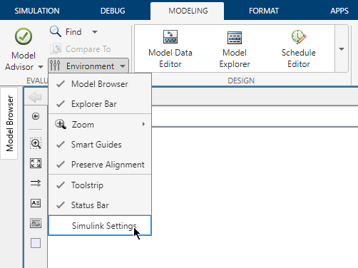
Simulink Editor is open on the Modeling tab with the Environment list expanded to show the Simulink Settings option

Model Finder: Added support to share and reuse model databases for team collaboration

Previously, to share a Model Finder database, you had to share the database file with team members, who would then manually import it in their settings folder using the Model Finder user interface (UI). Starting in R2026a, you can directly share and reuse model databases by using a shared repository and customizing the Model Finder UI with the MATLAB sl_customization function. By registering the customizations programmatically, you only need to do a one-time setup to access shared databases.

To set up a shared database, use Model Finder to create a database containing information of project related Simulink models. Store this database in a shared repository, such as a file server, cloud storage, or source code management (SCM) system.

To access the shared database, team members have to specify a customization to import the database to their Model Finder in the sl_customization.m file. After importing, the shared database appears in the Model Finder UI, and team members can search for models in the database.

To import the shared database wireless_systems.db from a shared repository and assign it the alias Shared Database, specify this customization in the customization file. Use the ModelFinderCustomizer class function on the customization manager object cm to specify the customization.

function sl_customization(cm)
dbPath = fullfile("simulink","modelfinderdatabases","wireless_systems.db");
cm.ModelFinderCustomizer.importDatabase(dbPath,“Shared Database”);
end
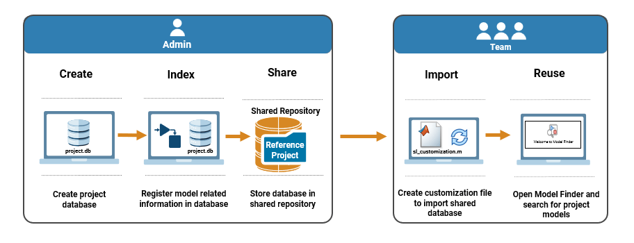
Workflow to create, share, and reuse Model Finder databases.

For more information, see Configure, Share, and Search Databases.

Change to default equation font

Starting in R2026a, equations on the Simulink canvas might display a modified default font due to an upgraded equation rendering engine. Additionally, on the Windows® operating system, user interface elements such as the Property Inspector now use the Windows system font, by default.

 Functionality being removed or changed

Simulink Fundamentals course will be discontinued

Warns

The Simulink Fundamentals course will be discontinued. You will be unable to start or continue this course after it is discontinued. Course progress and certificates will still be available.

To develop a broad skill set across core Simulink functionality, take these new courses instead:

These new courses provide the same material and more.

Options that have been removed from Simulink context menus

In R2026a, the context menus that appear when you right-click the Simulink model canvas or model elements such as blocks, signal lines, and annotations are changing. To maximize the compactness of the new context menus and the convenience of accessing frequently used options, some options have been removed from the context menus. The tables list some of these options and alternative ways to take the associated actions.

Block Context Menu

R2025b Context Menu ActionAction in R2026a
Right-click the block and select Find Referenced Variables.

Navigate into the model or component whose referenced variables you want to find. Right-click the canvas, and then click the Referenced Variables button .

Right-click the block and select Format > Flip Block Name.Select the block. In the Simulink Toolstrip, on the Format tab, click Flip Name.
Right-click the block and select Format > Fit to Content.Select the block. In the Simulink Toolstrip, on the Format tab, click Fit to Content.

Right-click any type of block representing a subsystem, for example an If Action Subsystem block, and select one of these options:

  • Format > Port Labels > None

  • Format > Port Labels > From Port Icon

  • Format > Port Labels > From Port Block Name

  • Format > Port Labels > From Signal Name

Select any type of block representing a subsystem, for example an If Action Subsystem block. In the Simulink Toolstrip, on the Format tab, in the Ports section, click the Port Labels button and select one of these options:

  • None

  • From Port Icon

  • From Block Name

  • From Signal Name

Right-click the block and select Format > Bring to Front.Select the block. In the Simulink Toolstrip, on the Format tab, click the Bring to front button .
Right-click the block and select Format > Send to Back.Select the block. In the Simulink Toolstrip, on the Format tab, click the Send to back button .

Top Model Canvas Context Menu

R2025b Context Menu ActionAction in R2026a
Right-click the model canvas and select Sample Time > All.Right-click the model canvas and select Information Overlays. Then, select all overlays under Sample Time.
Right-click the model canvas and select Sample Time > Off.Right-click the model canvas and select Information Overlays. Then, clear all overlays under Sample Time
Right-click the model canvas and set Animation Speed to Fast, Medium, Slow, or None.In the Simulink Toolstrip, on the Debug tab, set Animation speed to Fast, Medium, Slow, or None.

Annotation Context Menu

R2025b Context Menu ActionAction in R2026a
Right-click the annotation and select Format > Bring to Front.Select the annotation. In the Simulink Toolstrip, on the Format tab, click the Bring to front button .
Right-click the annotation and select Format > Send to Back.Select the annotation. In the Simulink Toolstrip, on the Format tab, click the Send to back button .

Right-click the annotation and select one of these options:

  • Text Alignment > Left

  • Text Alignment > Center

  • Text Alignment > Right

Right-click the annotation, and then click the Properties button . In the Annotation Properties dialog box, from Alignment, select one of these options:

  • Left

  • Center

  • Right

Right-click the annotation and select Enable Tex Commands.

Right-click the annotation, and then click the Properties button . In the Annotation Properties dialog box, select Enable TeX commands.

Right-click the annotation and select Show in Library Browser.Select the annotation. In the Simulink Toolstrip, on the Library tab, click Show Annotations in Library Browser.

Get extension point, action, and icon names of Simulink Context Menu widgets and Simulink Toolstrip widgets using slUIDeveloperMode function

Still runs

You can customize the Simulink Context Menu and the Simulink Toolstrip. For example, you can add your own custom toolstrip tabs and context menu items. The context menu and toolstrip are comprised of widgets. To reuse the action or icon of an existing widget for a custom widget, you need to know the name of that action or icon. To add context menu widgets, you need to know the names of extension points — predefined locations at which you can add widgets.

You can get the names of actions, icons, and extension points by entering developer mode, pausing your pointer on a widget, and pressing Ctrl (command ⌘ on macOS). The MATLAB Command Window outputs the action, icon, and extension point names for the widget.

In previous releases, you could only enter developer mode using the slToolstripDeveloperMode function. Starting in R2026a, you can also enter developer mode using the slUIDeveloperMode function.

slUIDeveloperMode("on")

The slToolstripDeveloperMode function will be removed in a future release.

For information about customizing the Simulink Context Menu, see Customize Simulink Context Menu Using Extension Points. For information about customizing the Simulink Toolstrip, see Create Custom Simulink Toolstrip Tabs.

Model Finder function updates

These Model Finder functions have been renamed:

Simulation Analysis and Performance

 Run Multiple Simulations in Parallel: Self-paced, interactive course available as part of Online Training Suite subscription

Run Multiple Simulations in Parallel is a new course that teaches you to:

  • Run multiple simulations of a Simulink model in parallel using the parsim function.

  • Perform post-simulation computations on simulation data.

  • Monitor simulations and visualize simulation data in the Simulation Manager.

For more information, see Run Multiple Simulations in Parallel.

 Configure Simulink Solvers to Improve Performance: Self-paced, interactive course available as part of Online Training Suite subscription

Configure Simulink Solvers to Improve Performance is a new course that teaches you to:

  • Configure the Simulink solver settings to gain finer control of simulation accuracy and optimize simulation speed.

  • Troubleshoot common simulation performance issues such as model stiffness and algebraic loops.

For more information, see Configure Simulink Solvers to Improve Performance.

Faster rapid accelerator simulations

Starting in R2026a, rapid accelerator mode introduces a persistent server that keeps libraries loaded between simulation runs. Keeping libraries in memory reduces the total simulation time by about 1.1 seconds for subsequent simulations. The improvement is most noticeable for smaller models with shorter simulation times, where library loading represents a larger portion of the total simulation time.

To measure this improvement, the following code was used in both R2025b and R2026a. The first simulation builds the rapid accelerator simulation target and loads the necessary libraries. In R2026a, when the simulation ends, the libraries remain in memory. The second simulation can then run without the overhead of loading these libraries. To compare total simulation times across releases, check the total elapsed wall time reported for the second simulation, which is in the simulation metadata.

mdl = "vdp";
openExample("simulink_general/VanDerPolOscillatorExample",SupportingFile=mdl)

out1 = sim(mdl,SimulationMode="rapid-accelerator");

out2 = sim(mdl,SimulationMode="rapid-accelerator",RapidAcceleratorUpToDateCheck="off");

t = out2.SimulationMetadata.TimingInfo.TotalElapsedWallTime;

The approximate times for the second simulation are

  • R2025b: 2.3s

  • R2026a: 1.2s

The code was timed on a Windows 10, AMD Ryzen 5 PRO 5650U @ 2.30 GHz test system.

Simulate models with algebraic loops faster by using rapid accelerator mode

You can now simulate models that contain algebraic loops using rapid accelerator mode and in applications deployed using Simulink Compiler. In previous releases, you could use only normal or accelerator mode to simulate models that contain algebraic loops. Rapid accelerator mode provides the fastest execution time by generating a simulation target that runs in a separate process. For more information, see How Acceleration Modes Work.

Apply time tolerance to external input data

When you load external input data for simulations, many input data formats require that you specify both time and data values to define the input. At each time step in the simulation, the block that loads the data determines the output value to provide to the simulation by comparing the current simulation time with the timestamps in the external input data. To control whether the software applies a tolerance when performing this comparison, use the new Input time tolerance model configuration parameter.

With this parameter enabled, the software considers the timestamp in the external input data and the simulation time equal if the timestamp is within 128*eps(t) of the simulation time t. You cannot modify the value of the time tolerance. The time tolerance applies to all external input data loaded using any of these blocks:

The Input time tolerance parameter is supported in all simulation modes, simulations deployed using Simulink Compiler, and production code generation.

Load external input data that contains Inf or NaN values

You can now load external input data that contains Inf and NaN data values using any of these blocks:

For example, to evaluate the system response to unexpected values, you can load external input data that contains one or more Inf or NaN values.

In previous releases, the software issued an error if external input data loaded using these blocks contained any Inf or NaN values.

Configure nontunable parameter values for fast restart simulations using the Simulation object

You can now use the Simulation object to configure nontunable parameter values for fast restart simulations.

  • You must specify the nontunable parameter values on the Simulation object before initializing or running the first fast restart simulation.

  • Once initialized in fast restart, you cannot modify nontunable parameter values.

  • Nontunable parameter values are not reverted in the model until you terminate the simulation or disable fast restart.

Previously, you could not specify nontunable parameter values on Simulation objects used to run fast restart simulations. To specify a nontunable parameter value, you had to modify the parameter value in the model before running the first fast restart simulation.

Analyze distribution of compilation time using the Simulink Profiler

The Simulink Profiler now provides information about how compilation time is distributed among compilation phases and among referenced models that simulate in normal mode. To view the compilation information, use one of these approaches:

  • In the Simulink Profiler, in the Profiler Report pane, click Show Execution Stack View . Then, expand the simulate and compilePhase nodes.

  • Inspect the rootExecNode property of the Simulink.profiler.Data object returned with the results of the profiling simulation.

In previous releases, the Simulink Profiler provided only the total time required to compile the model.
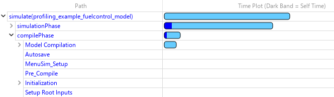
Compilation timing information in the Simulink Profiler.

Debug models using Model Slicer at breakpoints

Starting in R2026a, you can launch Model Slicer directly from the Breakpoints List when your Simulink model pauses at a breakpoint. This integration allows you to trace the signal values back to their sources so you can isolate the root cause of unexpected behavior in large models. A Simulink Check™ license is required to launch Model Slicer from the Breakpoints List.

In the Breakpoints List, Model Slicer:

  • Sets the starting point to the signal associated with the current breakpoint.

  • Updates the slice criteria to match the selected breakpoint when you add a new breakpoint or switch between existing breakpoints.

When model simulation hits a breakpoint, perform these steps to use Model Slicer from the Breakpoints List:

  1. On the Debug tab, click Breakpoints List. The Breakpoints List opens at the bottom of the Simulink Editor.

  2. In the Breakpoints List, click the Debug using Slicer button to debug the signal. You can also:

    • Add a starting point by clicking the Add Starting Point button .

    • View the upstream and downstream flow of the signals in the model using button.

  3. Click the Close Model Slicer button to close the Model Slicer.

For more information, see Breakpoints List and Trace Faulty Signal Paths Using Model Slicer at Signal Breakpoints (Simulink Check).

Improved support for breakpoints in accelerator mode

The Pause within time step option in the Breakpoints List now affects the behavior of breakpoints only in normal mode simulations. Supported breakpoints pause between time steps in accelerator mode simulations even if Pause within time step is selected. Previously, breakpoints were not supported in accelerator mode simulations if Pause within time step was selected.

Accelerator mode still does not support some breakpoints that normal mode supports. For example, breakpoints inside model references are not supported in accelerator mode.

The software now indicates which breakpoints are supported in accelerator mode by dimming unsupported breakpoints in the block diagram and the Breakpoints List. Previously, unsupported breakpoints appeared active during accelerator mode simulations but did not pause the simulation.

Selectively load signal data from an MLDATX file to the workspace

Starting in R2026a, you can inspect, filter, and load a subset of signals from an MLDATX file to the workspace by creating an mldatx.io.File object that references data in the MLDATX file. These operations do not require Simulink.

To access data in an MLDATX file, use mldatxfile to create an mldatx.io.File object. This object references signal data and metadata for runs saved in the file. Use the object to selectively load signals into the workspace.

  • Filter and export data with these functions:

    • getSignals — Filter signals based on criteria such as signal name, logging domain, or run index.

    • load — Export a subset of data from the MLDATX file to the workspace.

  • Inspect signal and run information with these functions:

    • getRunCount — Get the number of runs saved in the MLDATX file.

    • getRunInfoByIndex — Get detailed metadata for a run saved in the MLDATX file.

    • listRuns — Return a summary table of runs saved in the MLDATX file with columns for the run index, run name, creation date, and the name of the model that generated the run.

    • listSignals — Return a summary table of signals saved in the MLDATX file with columns for the signal name, run index, logging domain, block path, block sub-path, and port index.

To access data for an individual signal in an MLDATX file, use getSignals to create an mldatx.io.Signal object. This object references signal data and metadata for a signal saved in the MLDATX file and referenced by the mldatx.io.File object. Use the object to selectively inspect signal metadata and load data for a specific signal to the workspace using the load function.

When data is too large to fit into memory, use the getAsDatastore function to create a matlab.io.datastore.MLDATXSignalDatastore object to load the data into the workspace incrementally.

Live stream data to XY visualizations

Live streaming of data to XY visualizations in the Simulation Data Inspector, Record block, and XY Graph block is supported again. Such live streaming was supported in R2024b and earlier, but was not supported in R2025a. To live stream data to an XY visualization, data must be plotted as a scatter plot. To change the line style to only data markers, click Visualization Settings and in the Axes section, select Markers and clear Line. Trend lines are not supported while live streaming XY data.

Export data from the Simulation Data Inspector to a Parquet file

You can now export scalar and multidimensional signals from the Simulation Data Inspector to a Parquet file. The Simulation Data Inspector can export real and complex data of any built-in data type, as well as enumerations, strings, fixed-point data, buses, and arrays of buses. The Simulation Data Inspector can also export messages to a Parquet file as double values. When exporting to a Parquet file, you can configure shared or individual time columns, set row groups by height or size, and choose the compression used when saving the file.

Get and set data access for MATLAB callback functions programmatically

Programmatically configure and retrieve data access settings that enable streaming of signal data to a MATLAB callback function during simulation using the new Simulink.sdi.setDataAccess and Simulink.sdi.getDataAccess functions.

Get storage size of signals logged to the Simulation Data Inspector

You can now view the approximate storage size of data logged to the Simulation Data Inspector when a simulation is paused or stopped.

To interactively access storage size information, you can:

  • Add the Size column to the signal table in either the Inspect or Compare pane to display a specific property for all logged signals in the table.

  • View metadata for a signal, run, or comparison in the new Size row of the Properties pane.

For more information, see Inspect Signal, Run, and Comparison Metadata.

To programmatically access storage size information, you can:

In the signal table of the Simulation Data Inspector, the new Size column is highlighted. In the Preferences pane, the new Size row is highlighted.

Get descriptive statistics for signals in the Simulation Data Inspector

Starting in R2026a, get descriptive statistics for signals in the Simulation Data Inspector. Calculate statistics for the entire signal, or focus your analysis on a smaller time interval. The Simulation Data Inspector stores signals as Simulink.sdi.Signal objects. Use the signal ID of a Signal object to calculate these descriptive statistics:

  • max — Maximum signal value

  • min — Minimum signal value

  • bounds — Minimum and maximum signal value

  • mean — Mean of signal values

  • median — Median of signal values

  • std — Standard deviation

  • rms — Root mean square value

To get a set of descriptive statistics for a signal, use the Simulink.analytics.getMetrics function.

sigStats = Simulink.analytics.getMetrics(sigId)
sigStats = 

  struct with fields:

           min: 0
           max: 10
    peakToPeak: 10
          mean: 4.9038
        median: 4.9000
           std: 3.0245
           rms: 5.7462

Log data stores containing nonvirtual buses

Logging is now supported for data stores that output nonvirtual buses, nested nonvirtual buses, and arrays of buses.

Generate comparison reports with interactive plots using Simulation Data Inspector

Comparison reports in the Simulation Data Inspector let you share comparison data without MATLAB dependency. When you generate comparison reports from the Simulation Data Inspector, the plots are now interactive. You can zoom, pan and use data cursors in the plots. Prior to R2026a, plots were static images that did not have any interactive functionality.

For more information about generating comparison reports, see Create Interactive Comparison Reports.
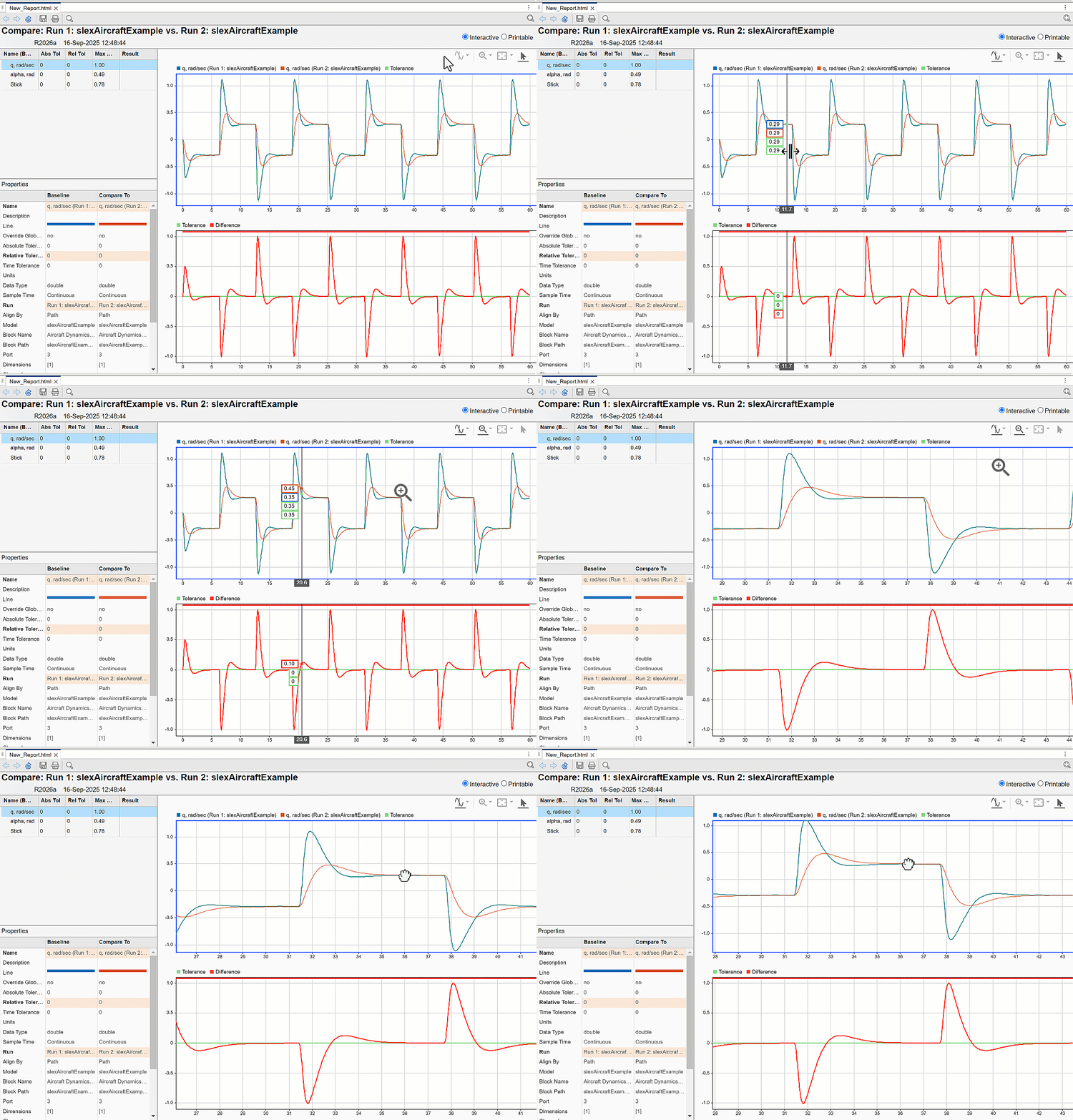
A generated comparison report. Data cursors, zooming and panning is displayed in the interactive plots on the right.

Accelerate JIT simulation with additional SIMD support

In R2026a, if your hardware supports the AVX2 or AVX512F SIMD instruction sets, you can use Hardware acceleration to speed up the simulation of just-in-time (JIT) models.

Run large-scale, system-level studies using parsim and Amazon Web Services (AWS)

The new example Scaling Virtual Calibration and System Design with parsim and AWS shows how to run large-scale, system-level studies using parsim and AWS.

 Functionality being removed or changed

The Simulation Data Inspector no longer exports data to the workspace by default when you create a new session or delete signals or runs

Behavior change

When you create a new session or delete runs or signals, the Simulation Data Inspector no longer exports data to the workspace before deleting signals or runs from the repository.

Component-Based Modeling

 Componentization Techniques for Simulink Models: Self-paced, interactive course available as part of Online Training Suite subscription

Componentization Techniques for Simulink Models is a new course that teaches you to:

  • Manage large Simulink models by organizing them into reusable components.

  • Select componentization strategies to enhance collaboration.

  • Build scalable model architectures.

  • Protect your models to help safeguard your intellectual property.

For more information, see Componentization Techniques for Simulink Models.

 Check for optimal model reference rebuild setting to avoid unnecessary compilations

To check that you are using the optimal model reference rebuild setting, in the Upgrade Advisor, run the Check if the model reference rebuild setting is optimal check.

Setting the Rebuild configuration parameter of the top model in a model hierarchy to If changes in known dependencies detected reduces the time required for change detection. The software automatically identifies most dependencies. However, in rare cases, to prevent invalid simulation and code generation results, you must explicitly specify dependencies on files that contain code executed by callbacks. For more information about known and specified dependencies, see Model dependencies.

For information about running checks in the Upgrade Advisor, see Upgrade Models Using Upgrade Advisor.

Create Model Hierarchy with Subsystems: Self-paced, interactive course available as part of Online Training Suite subscription

Create Model Hierarchy with Subsystems is a new course that teaches you to:

  • Reduce complexity and improve readability of Simulink models by grouping related blocks into subsystems.

  • Create and customize parameter dialog boxes for subsystems using masks.

  • Control the execution of your model by creating subsystems that execute in response to a control signal.

For more information, see Create Model Hierarchy with Subsystems.

Model System Components: Self-paced, interactive course available as part of Online Training Suite subscription

Model System Components is a new course that teaches you to:

  • Build larger projects for complex systems with multiple components.

  • Create and reference components as subsystems, separate models, or reusable libraries.

For more information, see Model System Components.

Check model componentization for faster model compilation

To speed up model compilation by converting subsystems to referenced models, in the Performance Advisor, run the Check model componentization check.

This check finds identical subsystems that have the same block diagram and interface. The check determines whether the subsystems satisfy at least one threshold criteria and converts the subsystems to referenced models where beneficial. The threshold criteria are the specified minimum number of copies and minimum number of constituent blocks.

This check is not run by default because it compiles the model hierarchy multiple times, which can be time consuming.

For more information about running checks in the Performance Advisor, see Improve Simulation Performance Using Performance Advisor.

Faster loading of model containing many instances of same referenced model

Loading a model that contains many instances of the same referenced model is faster in R2026a than in R2025b. The more times you reference the same model, the larger the performance improvement you experience.

For a simple example, suppose you create a model that references the vdp model many times. Open an example that uses the vdp model. Check that the vdp model is closed.

openExample("simulink_general/VanDerPolOscillatorExample")
close_system("vdp")

The following function creates a model that references the vdp model the number of times specified by num_instances. The function saves and closes the new model hierarchy and times how long it takes to load the top model.

function t = timingTest(num_instances)

% Create top model
topModel = "top";
new_system(topModel);
open_system(topModel);

% Add num_instances of vdp to top
refModel = "vdp";
for i = 1:num_instances
    add_block("simulink/Ports & Subsystems/Model", ...
        topModel+"/Model",MakeNameUnique="on", ...
        ModelName=refModel);
end

% Save and close top model
close_system(topModel,1);

% Measure performance of load_system function
tic;
load_system(topModel);
t = toc;

% Close and delete top model
close_system(topModel);
topFile = topModel+".slx";
delete(topFile);

end

Loading a model that contains 10 to 100 instances of a referenced model like vdp is about 1.9–2.8x faster than in the previous release.

This table provides the approximate execution times.

Number of InstancesR2025bR2026a
100.34 s0.18 s
200.43 s0.23 s
500.80 s0.40 s
1001.6 s0.57 s

This evaluation was performed on a Windows 11, AMD EPYC™ 74F3 @ 3.19 GHz test system.

For more information about model references, see Model Reference Behavior and Capabilities.

Faster saving for large model reference hierarchies

Saving a model hierarchy that contains many modified referenced models is faster in R2026a and R2025b than in R2025a. The more modified referenced models and levels of model hierarchy, the larger the performance improvements you experience.

The following function creates a vertical model reference hierarchy composed of the number of models specified by num_models. The function modifies each model in the hierarchy and times how long it takes to save the models. The function uses a temporary directory. After timing, the function closes the models and removes the temporary directory.

function t = timingTest(num_models)

% Navigate into temporary directory
currDir = pwd;
tempDir = tempname;
mkdir(tempDir)
cd(tempDir)

% Track created models
createdModels = cell(1,num_models);
topModel = "Model1";

% Create the hierarchy: Model1 -> Model2 -> ... -> ModelN
for i = num_models:-1:1
    mdl = sprintf("Model%d",i);
    createdModels{i} = mdl;
    new_system(mdl);
    open_system(mdl);
    if i < num_models
        refName = sprintf("Model%d", i+1);
        add_block("simulink/Ports & Subsystems/Model", ...
            mdl+"/Model",ModelName=refName);
    end
    save_system(mdl);
end

% Make all models in hierarchy dirty
cellfun(@(x) set_param(x,Description="Dirty"),createdModels);

% Measure performance of save_system function
tic;
save_system(topModel,SaveDirtyReferencedModels="on");
t = toc;

% Close created models
cellfun(@(x) close_system(x), createdModels);

% Remove temporary directory and created models
cd(currDir)
rmdir(tempDir,"s")

end

The performance improvement increases with the number of modified referenced models and levels of model hierarchy:

  • For a vertical model reference hierarchy that contains 10 modified models, saving the models is about 2x faster than in R2025a.

  • For a vertical model reference hierarchy that contains 50 modified models, saving the models is about 4x faster than in R2025a.

This table provides the approximate execution times.

Number of ModelsR2025aR2025bR2026a
101.5 s0.82 s0.86 s
203.6 s1.7 s1.6 s
306.4 s2.9 s2.4 s
5017 s4.6 s4.2 s

This evaluation was performed on a Windows 11, AMD EPYC 74F3 @ 3.19 GHz test system.

For more information about model references, see Model Reference Behavior and Capabilities.

Linearly interpolate outputs of model references configured to use local solvers

When a parent solver takes a step that does not correspond to a communication step for a local solver, Model blocks that reference models configured to use a local solver provide an interpolated output value to the parent solver. You can now configure Model blocks that produce real, double, continuous output signals to linearly interpolate these output values.

To configure a model reference to linearly interpolate output values, set the Output signal handling parameter of the Model block to Linear. For parent solver time steps that do not correspond to communication steps, the Model block provides outputs by linearly interpolating the output value from the last communication step and the value the local solver computed for the next communication step.

When you set Output signal handling to Auto, the software now selects linear interpolation in some cases. For details, see Auto output signal handling selects linear interpolation in some cases.

Linear output signal handling has these advantages over zero-order hold output signal handling:

  • Simulation results are closer to the results of a simulation that uses a single solver.

  • Output signal sample times do not change across the model reference boundary.

  • Retaining continuous sample time across the model reference boundary can result in fewer parent solver resets.

In previous releases, only zero-order hold output signal handling was supported for variable-step local solvers and for fixed-step solvers that have a smaller step size than the parent solver.

For more information, see Use Local Solvers in Referenced Models.

Use local solvers for models that reference hybrid models

Local solvers are now supported for referenced models that directly or indirectly reference another model that has both continuous and discrete sample times.

In previous releases, local solvers are not supported for such model references, with a couple exceptions.

For more information, see Use Local Solvers in Referenced Models.

Reference hybrid, fixed-step model from variable-step parent

A variable-step model can now reference a fixed-step, single-tasking model that has both continuous and discrete sample times.

For more information, see Specify Compatible Solver Settings.

Assign new bus objects and identify mismatches at bus element ports more easily

When a bus element port does not specify a Simulink.Bus object, you can now create and assign Simulink.Bus objects from the Property Inspector or port dialog box by clicking Create and assign bus objects for this bus hierarchy, compiling the model when needed. The software compiles the model and then creates and assigns the Simulink.Bus objects. In previous releases, creating and assigning Simulink.Bus objects to bus element ports requires multiple steps.

When you create Simulink.Bus objects after opening the Property Inspector or port dialog box, to update the Data type list, select Refresh data types from the list. In previous releases, clicking Refresh updates the entire dialog box, including the Data type list.

When a bus element port specifies a Simulink.Bus object and the incoming bus hierarchy does not match the specified bus object, the Property Inspector and port dialog box now display only the mismatched elements in red. Mismatched elements include:

  • Elements that are accessed by blocks but are missing from the bus object

  • Elements that are specified by bus objects but do not match incoming elements

  • Parents of mismatched elements

In previous releases, when an element does not match, the entire bus hierarchy is red, not just the mismatched elements.

For more information, see In Bus Element and Out Bus Element.

Propagate names between bus element ports and components more intuitively

When you connect an In Bus Element or Out Bus Element block to a port on a Subsystem block, a custom port or element name replaces a default port or element name. Previously, the software ignored element names when renaming.

For a custom name from a port on a Model block to replace a default port or element name at an In Bus Element or Out Bus Element block, the referenced model must be loaded. The names of the ports on a Model block are determined by the referenced model and are not changed.

For more information, see Connect Port Blocks to Subsystems.

Successively add bus elements to bus element ports

When you add an element to a bus in a bus element port, the selection remains on the parent instead of changing to the new element. You can now add multiple elements to a bus without reselecting the parent before adding each element.

For an example, see Specify Multiple Input Signals at One Port.

Initialize Model blocks by specifying initial operating points

You can now load a partial operating point for simulation by specifying the initial operating point of one or more Model blocks in the model hierarchy. When you specify an initial state or operating point for the top model, you can specify a Model block operating point to override the state or operating point information for the block.

In previous releases, you had to specify a complete operating point for the top model. The operating point of the top model initializes the entire model hierarchy.

You can configure multiple Model blocks in the same model hierarchy to save the final operating point or simulate from an initial operating point. By default, each Model block operating point is saved as a Simulink.op.ModelBlockOperatingPoint object in a property of the Simulink.SimulationOutput object returned by the simulation.

Saving and loading Model block operating points is not supported for Model blocks that:

  • Simulate in a mode other than normal mode

  • Reference a model that is referenced by another Model block in the hierarchy

  • Are part of a variant subsystem or variant assembly subsystem

Count all blocks used in system and its references using sldiagnostics

Using sldiagnostics, you can now count all blocks used in a system and its references by setting the CountBlocksInRefs option.

Merge Simulink cache file contents

When you generate multiple Simulink cache files for the same model, you can now merge the contents of those files in one Simulink cache file. To support the merge, platform-specific artifacts, such as simulation and code generation targets, must be unique. For example, the cached model reference simulation targets must have different releases or platforms than each other.

To merge Simulink cache file contents in a new file, use the slxcmerge function. For more information, see slxcmerge.

Easily copy subsystem content to new model after failed conversion

When the Model Reference Conversion Advisor fails to convert a subsystem to a model, the advisor now provides an option to copy the subsystem block diagram to a new model. The new model uses the configuration set from the original parent model. If you want to force the conversion and resolve errors manually after the conversion, use this option.

For more information about the conversion process, see Convert Subsystems to Referenced Models.

Models created from subsystems can retain Polyspace comments

When you convert a subsystem to a model, you can now retain Polyspace comments specified by the PolySpaceStartComment and PolySpaceEndComment block property tokens. To copy the Polyspace comments from the subsystem to the new model, use the Simulink.SubSystem.convertToModelReference function with CopyPolyspaceComments set to true.

For information about block property tokens, see Specify Block Properties.

Simulink Units: Ordinal units specifications now supported

Simulink now supports ordinal unit specifications, such as beaufort_wind_scale. Blocks now support units that provide relative ranking, but the intervals between the values are not evenly distributed.

Highlight bounded regions of Variant Start and Variant End blocks for enhanced visual representation

You can now highlight the blocks within a bounded region created by Variant Start and Variant End blocks to distinguish them visually from other components. This feature enables you to trace data flow and logic specific to each variant implementation in large and complex models.

Consider the slexVariantStartAndEnd model, which contains the Variant Start and Variant End blocks that define the bounded regions.

To identify the blocks within the bounded region created at Port 2 of the Variant Start block:

  1. In the Simulink Toolstrip, on the Debug tab, select Information Overlays > Start End Bounded Regions.

  2. On the Variant Start End Bounded Regions tab, expand slexVariantStartAndEnd/Variant Start and choose Port 2. Alternatively, click the output signal connected to Port 2 of the Variant Start block to highlight the blocks within its bounded region.

Block highlighting applies only to the model in which it is enabled and does not extend to the bounded regions in the referenced models. To highlight blocks within a bounded region of a referenced model, open the referenced model and select the Start End Bounded Regions option within that model. For more information, see Control Variant Condition Propagation using Variant Start and Variant End Blocks.
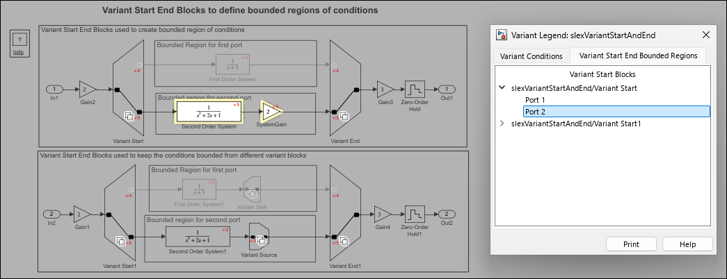
Highlighted blocks within the bounded region of port 2 of the Variant Start block in the slexVariantStartAndEnd model

Variant Manager for Simulink: Use instance-specific values for variant control variables

Starting in R2026a, Variant Manager supports instance-specific values for variant control variables when you define these variables in the model workspace and configure them as model arguments.

When you configure a variant control variable as a model argument and reference the model using multiple Model blocks, you can assign either the same value or different values to each instance of the variable in the model hierarchy. The instance-specific value for this variable can come from the model workspace of the referenced model, the parent model reference hierarchy, or a system mask applied to the referenced model. Variant Manager identifies this instance-specific definition and uses it when importing control variables, finding control variable usage, and activating the model.

For more information on the use of instance-specific values, see Configure Instance-Specific Values for Block Parameters in a Referenced Model.

Variant Manager for Simulink: Use variant control variables with the same name defined in multiple sources when generating configurations

When you automatically generate variant configurations by using Variant Manager or the Simulink.VariantManager.generateConfigurations function, you can use variant control variables with the same name defined in multiple sources, except in the preconditions to be applied when generating configurations.

In the Generate Configurations tab of the Variant Manager window, the Configure Control Variables table has a new Source column that shows the source of the control variables used by the model hierarchy. The generated configurations also identify variables with multiple definitions by their source.
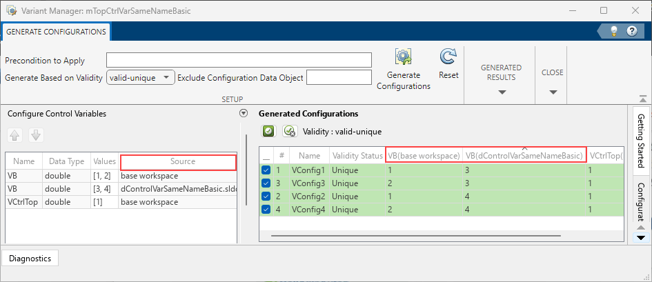
Generate Configurations tab of Variant Manager window shows the Source column in the Configure Control Variables table. The results pane shows the control variable name with the source name in the header column.

Variant Manager for Simulink: Open Variant Manager using Simulink.VariantManager.open function

You can now use the Simulink.VariantManager.open function to open Variant Manager from the MATLAB command line. You can provide a block diagram name, a block path, or a Simulink.BlockPath object as input to this function. You can also use this function to open the Simulink.VariantConfigurationData object dialog box to define and edit variant configurations and constraints without a Simulink model.

Variant Manager for Simulink: Analyze variant models using Simulink.VariantManager.analyzeModel function

You can use the Simulink.VariantManager.analyzeModel function to programmatically analyze variant configurations for a model. Specify either named variant configurations or variable groups as input to the function.

The function analyzes the model using the specified configurations and opens the variant analysis report. This is the default behavior if you do not specify an output argument in the function call. The function can also return a Simulink.VariantConfigurationAnalysis object as an output argument. You can call functions of this object to perform further operations on the analysis results.

For more information on Variant Analyzer, see Analyze Variant Configurations in Models Containing Variant Blocks.

Variant Manager for Simulink: Simulation support for models with variant configuration data without installing support package

Starting in R2026a, you can simulate models that have variant configurations defined and stored in an associated Simulink.VariantConfigurationData object without installing the Variant Manager for Simulink support package.

You can view the variant configurations and constraints saved in the Simulink.VariantConfigurationData object. If the object is defined in the base workspace, double-click the object or use the open function at the MATLAB command line. If the object is in a data dictionary, select the object in the Model Explorer. Selecting the object opens the Simulink.VariantConfigurationData dialog box in a read-only mode. For more information, see Manage Variant Configurations Without Simulink Model.
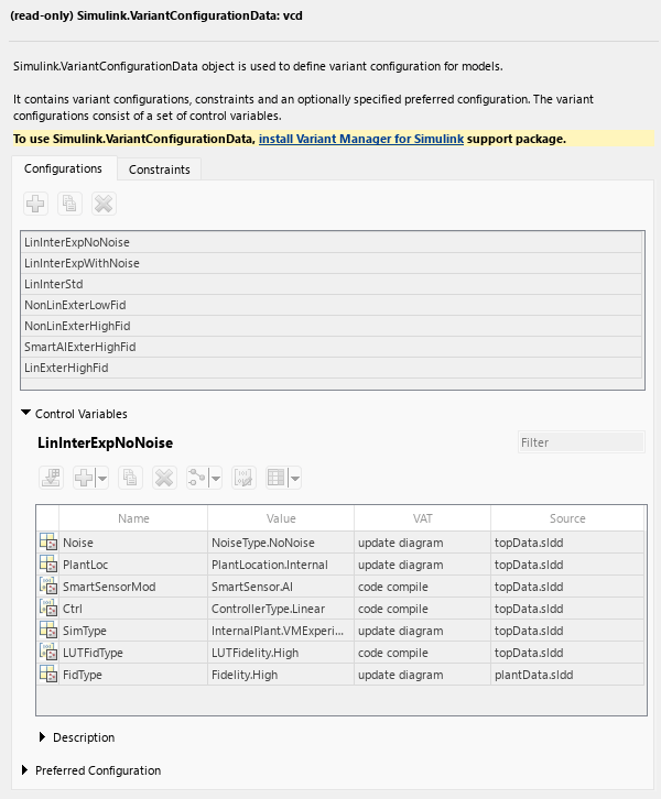
Simulink.VariantConfigurationData dialog box shows a read-only view of the configurations.

You can run single or multiple parallel simulations on the model programmatically without specifying a named variant configuration. For example, these commands run successfully without the support package installed:

openExample("slexVariantManagement.slx");
sim("slexVariantManagement.slx")
However, running a simulation using the Simulink.SimulationInput object by specifying a named variant configuration, as shown below, results in an error if the support package is not installed.
simInp = Simulink.SimulationInput("slexVariantManagement.slx")
simInp = setVariantConfiguration(simInp,'LinInterExpWithNoise')
sim(simInp,"ShowProgress","on");

Previously, since R2022b, you could not simulate models containing variant configurations unless you installed the Variant Manager for Simulink support package.

Variant Manager for Simulink: Reduce models containing Function Element and Function Element Call blocks

Variant Reducer now supports reducing models that contain Function Element and Function Element Call blocks.

Variant Manager for Simulink: Specify arguments of Simulink.VariantConfigurationData object functions using Name=Value syntax

Starting in R2026a, functions of the Simulink.VariantConfigurationData object support specifying input arguments using the Name=Value syntax. This enhancement improves usability and aligns the syntax with other functions provided by Variant Manager for Simulink. Functions of the Simulink.VariantConfigurationData object continue to support positional arguments, but it is recommended to use the Name=Value syntax instead.

For example, the following table compares the positional argument syntax and the newly supported Name=Value syntax for the addConfiguration function. Here, varconfigdata is a Simulink.VariantConfigurationData object.

Before R2026aFrom R2026a

addConfiguration(varConfigData, ...
 "InternalPlantConfig", ...
 "Internal Plant Controller", ...
 ctrlVarStruct);

addConfiguration(varConfigData, ...
 ConfigurationName="InternalPlantConfig", ...
 Description="Internal Plant Controller", ...
 ControlVariables=ctrlVarStruct);

Variant Manager for Simulink: Improved performance when activating named variant configurations

In R2026a, when you activate a named variant configuration in Variant Manager for Simulink, the operation completes sooner for large models that contain many referenced models compared to R2025b.
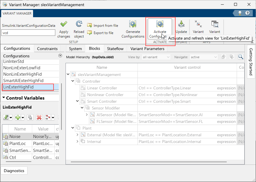
Variant Manger window highlights a named configuration and the Activate button.

Optimize block activation by propagating variant conditions through signal loops

In previous releases, variant conditions specified in variant blocks did not propagate to the blocks that form signal loops. The blocks forming these loops remained active during simulation and code generation. Starting in R2026a, variant conditions propagate through signal loops. The blocks inside and outside the loop along the signal path activate or deactivate based on their associated variant conditions. As a result, only blocks required for the active variant are simulated and included in the generated code, eliminating the unnecessary inclusion of inactive blocks.

For example, in this model, the variant condition V == 1 from the Variant Source block propagates to the Sum, Integrator, Gain, and Unit Delay blocks that form the signal loop and to the Constant block outside the loop. These blocks activate only when V == 1 evaluates to true.
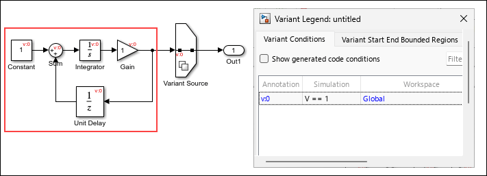
Blocks in signal loop and a connected Constant block are highlighted to show they are active only when the variant condition V == 1 evaluates to true.

Convert referenced subsystem to a regular subsystem from the Simulink Editor

You can now convert a Subsystem Reference block to a Subsystem block directly from the Simulink Editor by using either of these ways:

  • Right-click the Subsystem Reference block and select Convert to > Subsystem.

  • Select the Subsystem Reference block, go to the Subsystem Block tab, and select Convert > Convert to Subsystem.

Previously, you could convert a Subsystem Reference block to a Subsystem block only from the MATLAB Command Window.

For more information, see Convert Subsystem Reference Block to Subsystem Block in Convert Between Subsystems and Referenced Subsystems.

Change active variant during run time using Simulation object

Starting in R2026a, you can switch the active variant during simulation by using the setVariable or setBlockParameter function of a Simulation object to write to a variant control variable while simulation is paused. Previously, you could switch the active variant choice of a Variant Subsystem block during simulation or execution of the generated code only by using a Parameter Writer block to write to a variant control variable.

This code pauses a simulation, then demonstrates how to switch the active variant choice for different locations of the variant control variable.

% start simulation
mdl = "runtimeVariant";
open_system(mdl);
s = simulation(mdl)
 
% update variant control variable stored in a global workspace
s = setVariable(s,"V",0);
step(s,PauseTime=5);
s = setVariable(s,"V",1);

% update variant control variable that is a Simulink.Parameter object stored in a model workspace
s = setVariable(s,"M.Value",int32(1),"Workspace","runtimeVariant");
step(s,PauseTime=5);
s = setVariable(s,"M.Value",int32(2), "Workspace","runtimeVariant");

% update variant control variable stored in a mask workspace
s = setBlockParameter(s,"runtimeVariant/MaskSubsystem","V","1");
step(s,PauseTime=5);
s = setBlockParameter(s,"runtimeVariant/MaskSubsystem","V","2");

% update a variant control variable as a model argument
s = setBlockParameter(s,"runtimeVariant/Model", "ParameterArgumentValues", struct("V","1"));
step(s,PauseTime=5);
s = setBlockParameter(s,"runtimeVariant/Model", "ParameterArgumentValues", struct("V","2"));
 
% resume simulation
step(s,PauseTime=10);
out = stop(s);

For more information, see Control Active Choice of Variant Subsystem During Simulation or Execution of Generated Code.

Visualize connection between Parameter Writer block and base workspace or model workspace variables

Starting in R2026a, you can visualize the connection from a Parameter Writer block to a base workspace or model workspace variable in the Connectors tool. For example, you can now visualize the connection between a Parameter Writer block writing to a variant control variable in the base workspace and a Variant Subsystem block as the parameter owner block. Previously, when you selected Parameter Connectors, the Connectors tool displayed the connection from a Parameter Writer block only when the destination was a block parameter.

To display the connection to workspace variables, in the Connectors tool, select Parameter Connectors. Then, compile the model.

The Connectors tool is available in the Information Overlays menu on the Debug tab of the Simulink Editor.

For more information on using the Connectors tool, see Use Connectors Tool to Visualize Relation Between Blocks.

Generate code for Parameter Writer block with inlined parameters

Starting in R2026a, you can generate code for a Parameter Writer block, writing to a variable with non-auto storage class attributes, with inlined parameters by setting the model parameter to Inlined. Previously, you could only generate code for a Parameter Writer block when the model configuration parameter Default parameter behavior (Simulink Coder) was set to Tunable.

For example, you can now generate code for a Parameter Writer block that writes to the run-time variant control variable for a Variant Subsystem block regardless of the Default parameter behavior setting.

Use Parameter Writer block to initialize variant control value of variant parameter bank

In R2025a, you could use Parameter Writer blocks within an Initialize Function block to initialize Simulink.VariantControl objects associated with variant parameters (Simulink.VariantVariable) that have a startup activation time. Starting in R2026a, you can use variant parameter banks (Simulink.VariantBank) to group such variant parameters.

With this enhancement, the Parameter Writer block can initialize the variant control used by the variant parameter bank, enabling you to select the active choice of the bank at the start of simulation or during the initialization of generated code. You must define both the variant parameters and the variant parameter bank in the base workspace or in a data dictionary associated with the model. In the code generated by Embedded Coder, the Parameter Writer block initializes the Simulink.VariantControl object, which in turn selects the active value set from the variant parameter bank structure array. For an example, see Initialize Variant Control Value of Variant Parameter Bank Using Parameter Writer Block.

For information on code generation using variant parameter banks, see Group Variant Parameter Values and Conditionally Switch Active Value Sets in Generated Code (Embedded Coder).

Generate code for model that references protected model containing variant parameters with code compile activation time

In R2026a, you can generate code for a model that includes a protected model when the protected model contains variant parameters with code compile variant activation time. The generated code for the parent model does not contain preprocessor conditional statements for the declarations and definitions of these variant parameters. This code is similar to code generated for such a model when you set the variant parameter activation time to update diagram analyze all choices.

In this example, the parent model refers to a protected model that uses two variant parameters K and Kv, that use a variant control V, with code compile activation time.
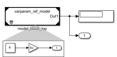
Parent model uses a protected model that contains two variant parameters.

When you generate code for this model using Embedded Coder, the code for the parent model defines the variant parameters without conditionally compiling them based on variant control V, and the code contains only the active choice of the variant parameters.

 /* File: varparam_top_model.h */

/* Model block global parameters (default storage) */
extern real_T rtP_K;                   /* Variable: K
                                        * Referenced by: '<Root>/model_block_top'
                                        */
extern real_T rtP_Kv;                  /* Variable: Kv
                                        * Referenced by: '<Root>/model_block_top'
                                        */
/* File: varparam_top_model_data.c */

/* Model block global parameters (default storage) */
real_T rtP_K = 2.0;                    /* Variable: K
                                        * Referenced by: '<Root>/model_block_top'
                                        */
real_T rtP_Kv = 3.0;                   /* Variable: Kv
                                        * Referenced by: '<Root>/model_block_top'
                                        */
Protected model code generation does not support preprocessor conditional statements, so the generated code for the protected model also considers only the active choice of the variant parameter.
/* File: varparam_ref_model.c */
/* Output and update for referenced model: 'varparam_ref_model' */
void varparam_ref_model(real_T *rty_Out1)
{
  /* Gain: '<Root>/Gain' incorporates:
   *  Constant: '<Root>/Constant'
   */
  *rty_Out1 = rtCP_Gain_Kv * rtCP_Constant_K;
}

If the parent model uses the same variant parameter as the protected model with code compile activation time, then the generated code for the parent model guards that variant parameter using the preprocessor conditionals #if and #elif.

In this example, the parent model also uses the variant parameter K.
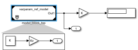
Parent model uses the variant parameter K that is also used by the protected model.

The code generator uses the macro V to emit #if and #elif guards that conditionally compile K.

/* File: varparam_top_model_has_vparam_types.h */

#ifndef V
#define V                              1
#endif
/* File: varparam_top_model_has_vparam.h */
/* Model block global parameters (default storage) */
#if V == 1 || V == 2

extern real_T rtP_K;                   /* Variable: K
                                        * Referenced by: '<Root>/model_block_top'
                                        */

#endif

extern real_T rtP_Kv;                  /* Variable: Kv
                                        * Referenced by: '<Root>/model_block_top'
                                        */
/* File: varparam_top_model_has_vparam_data.c */
/* Model block global parameters (default storage) */
real_T rtP_Kv = 3.0;                   /* Variable: Kv
                                        * Referenced by: '<Root>/model_block_top'
                                        */

#if V == 1

real_T rtP_K = 2.0;                    /* Variable: K
                                        * Referenced by: '<Root>/model_block_top'
                                        */

#elif V == 2

real_T rtP_K = 4.0;                    /* Variable: K
                                        * Referenced by: '<Root>/model_block_top'
                                        */

#endif

Improved error handling for models with variants and buses

Simulink no longer reports bus propagation errors for inactive variant paths or blocks with Variant activation time set to update diagram.

For more information on using Variant Subsystem blocks, see Implement Variations in Separate Hierarchy Using Variant Subsystems.

Specify value of Simulink.VariantControl as Boolean value

Starting in R2026a, you can specify the value of Simulink.VariantControl objects as Boolean values. You can also set the value of a variant control object to a Simulink.Parameter object with a Boolean value. This enhancement is supported for simulation and code generation workflows, including code generation targets such as AUTOSAR. For example,

vCtrl = Simulink.VariantControl(Value=true,ActivationTime="startup");
vCtrlSP = Simulink.VariantControl(Value=Simulink.Parameter(Value=true));
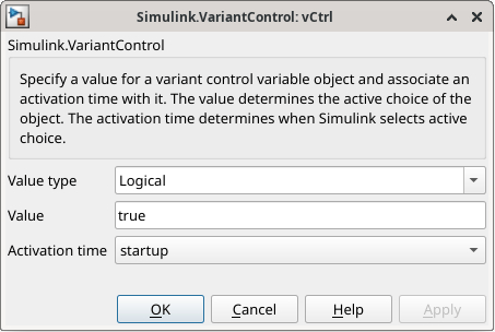
Variant control dialog box shows the type as logical and value as true.

This model uses a Simulink.VariantControl object vCtrl with a Boolean value to switch between the choices of a Variant Source block.
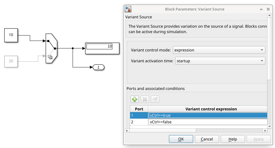
Model that contains a Variant Source block with two constant blocks as input is shown. The block parameter dialog box of the Variant Source block is shown.

This code snippet shows the definition of the variant control vCtrl and its usage in the model step function in the code generated using Simulink Coder.

/* Exported block parameters */
boolean_T vCtrl = true;                /* Variable: vCtrl
                                        * Referenced by:
                                        *   '<Root>/Constant'
                                        *   '<Root>/Constant1'
                                        *   '<Root>/vCtrl'
                                        */
/* Model step function */
void modelVCwithBool_step(void)
{
  /* SignalConversion generated from: '<Root>/Variant Source' */
  if (vCtrl) {
    /* Outport: '<Root>/Out1' incorporates:
     *  Constant: '<Root>/Constant'
     */
    modelVCwithBool_Y.Out1 = modelVCwithBool_P.Constant_Value;
  } else {
    /* Outport: '<Root>/Out1' incorporates:
     *  Constant: '<Root>/Constant1'
     */
    modelVCwithBool_Y.Out1 = modelVCwithBool_P.Constant1_Value;
  }
}

Group member definitions of integer-based enumerated types using Members argument

When defining integer-based enumerated types using the Simulink.defineIntEnumType function, you can use the new argument Members to group each member’s name, value, and description into a single cell array. The member description is a new and optional property.

Consider the enumeration named Colors with three members, Red, Yellow, and Green. Each member has an associated integer value and description.

NameValueDescription
Red0Stop!
Yellow1Prepare to stop!
Green2Go!

Use the Members argument to define the name, value, and description for each member of the enumerated type Colors in a single array.

Simulink.defineIntEnumType("Colors", ...
         "Members",{{"Red",0,"Description","Stop!"}, ...
               {"Yellow",1,"Description","Prepare to stop!"}, ...
               {"Green",2,"Description","Go!"}}, ...
         "Description"="Traffic light colors", ...
         "DefaultValue"="Red", ...
         "StorageType"="int16");

The generated code includes the description for each member as a comment next to the corresponding enumeration member.

typedef enum {
 Red= 0, /* Stop! (default value) */
 Yellow  /* Prepare to stop! */
 Green   /* Go! */} Colors;

Specify Callback Functions for Multiversion Co-Simulation Components in Block Dialog

You can now specify callback functions for Multiversion Co-simulation components in the Multiversion Co-simulation block dialog. These are the supported block callbacks and their corresponding model callbacks in Simulink.

  • CosimPreLoadFcn - PreLoadFcn

  • CosimPostLoadFcn - PostLoadFcn

  • CosimInitFcn - InitFcn

  • CosimStartFcn - StartFcn

  • CosimStopFcn - StopFcn

Before R2026a, only PreLoadFcn and PostLoadFcn were supported and had to be defined in a separate script. You can now manage component callbacks directly on the block dialog.
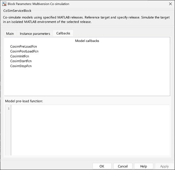
Multiversion Co-simulation block dialog callbacks

Simulink.importExternalCTypes: Enhanced Support For Custom Type Import and Compiler Flags

Starting in R2026a, the Simulink.importExternalCTypes function allows you to:

  • Generate a header file containing the type alias corresponding to the type signatures from an external header file using the SimulinkTypeAliasHeader argument.

  • Import types with type names that contain the original type signatures from an external header file using the UseFullyQualifiedName argument.

  • Add additional flags to the compiler command line using the CompilerFlags argument.

Access compiled port attributes without model recompilation

Starting in R2026a, you can access compiled port attributes — such as complexity, data type, units and width of data and state ports — in a previously compiled model without requiring the model to be in an active compilation state. This change saves time in cases where model compilation is time-consuming.

For a model that has been successfully compiled once before in the current MATLAB session, this enhancement makes accessing complexity, data type, units and width attributes simpler. The feval based compiled attribute access continues to work as before.

For example, this table compares the access pattern for complexity in a previously compiled model for versions R2025b and earlier with the versions R2026a and later.

R2025b and earlierR2026a and later

feval(gcs,[],[],[],"compile");
cs = get_param(gcb,"CompiledPortComplexSignals")
feval(gcs,[],[],[],"term");

cs = get_param(gcb,"CompiledPortComplexSignals")

Use Simulink Units with FMU block

Starting in 2026a, the input and output ports of the FMU Import block can read and propagate units. You can use signals with built-in and user-defined units at the block interface.

Simulink Support Package for Rust Code (April 2026)

Starting in R2026a, you can use the Simulink Support Package for Rust® Code to interface Rust code with Simulink. To use this support package, you must install this support package as an add-on. For more information, see Install Simulink Support Package for Rust Code.

Using the support package, you can:

 Functionality being removed or changed

Rebuild configuration parameter default value is now If changes in known dependencies detected

Behavior change

By default, new models set Rebuild to If changes in known dependencies detected instead of If changes detected. The new default value reduces the time required for change detection.

The software automatically identifies most dependencies. However, in rare cases, to prevent invalid simulation and code generation results, you must explicitly specify dependencies on files that contain code executed by callbacks. For more information about known and specified dependencies, see Model dependencies.

Rebuild and Never rebuild diagnostic configuration parameters will be removed

Warns

The Rebuild and Never rebuild diagnostic configuration parameters will be removed in a future release.

In the Configuration Parameters dialog box, these parameters have been moved under Advanced parameters at the bottom of the Model Referencing pane.

The software now issues warnings when:

  • You update, simulate, or build a model with Rebuild set to a value other than If changes in known dependencies detected.

  • In the MATLAB Command Window, you specify an UpdateModelReferenceTargets value other than "IfOutOfDate".

  • In the MATLAB Command Window, you specify a CheckModelReferenceTargetMessage value.

The future behavior will match the If changes in known dependencies detected setting of the Rebuild configuration parameter.

  • To rebuild model reference targets conditionally, set Rebuild to If changes in known dependencies detected. To check for changes in files that contain code executed by callbacks, use the Model dependencies configuration parameter. For more information, see Model dependencies.

  • To rebuild model reference targets unconditionally, remove the related Simulink cache files and model reference targets. For more information, see Manage Simulation Targets for Referenced Models and Manage Build Process Folders (Simulink Coder).

  • To avoid rebuilding model reference targets, convert the referenced models to protected models. For more information, see Protect Models to Conceal Contents (Simulink Coder).

UpdateThisModelReferenceTarget argument of slbuild function will be removed

Warns

The UpdateThisModelReferenceTarget name-value argument of the slbuild function will be removed in a future release. This argument lets you build the model reference simulation or coder target for only the specified model and not its referenced models.

To avoid rebuilding model reference targets for referenced models, convert the referenced models to protected models instead. For more information, see Protect Models to Conceal Contents (Simulink Coder).

To control what model reference targets build during simulation or code generation, use the strategies in this table instead.

UpdateThisModelReferenceTarget ValueRecommended Replacement
"IfOutOfDate" or "IfOutOfDateOrStructuralChange"

To rebuild model reference targets conditionally, set the UpdateModelReferenceTargets configuration parameter to "IfOutOfDate". To check for changes in files that contain code executed by callbacks, use the ModelDependencies configuration parameter. For more information, see Model dependencies.

"Force"

To rebuild model reference targets unconditionally, remove the related Simulink cache files and model reference targets. For more information, see Manage Simulation Targets for Referenced Models and Manage Build Process Folders (Simulink Coder).

Enable parallel model reference builds configuration parameter no longer has dependencies

Behavior change

The Enable parallel model reference builds configuration parameter no longer depends on the Rebuild and Never rebuild diagnostic configuration parameters. When Rebuild is set to Never, the software does not rebuild model reference targets, and the Enable parallel model reference builds configuration parameter does not start a parallel pool of workers.

Previously, the Enable parallel model reference builds configuration parameter was disabled when Rebuild was set to Never and Never rebuild diagnostic was set to None.

For more information, see Enable parallel model reference builds.

Port and parameter mismatch and Model block version mismatch configuration parameters will be removed

Still runs

The Port and parameter mismatch and Model block version mismatch diagnostic configuration parameters will be removed in a future release. After removal, Model blocks will refresh without diagnostics for port, parameter, or version mismatches. This behavior is the current default behavior.

To update your code, remove commands that interact with the ModelReferenceIOMismatchMessage and ModelReferenceVersionMismatchMessage configuration parameters.

For more information about Model block refreshes, see Refresh Model Blocks.

Models created from subsystems use referenced configuration sets with overridden parameter values

Behavior change

When you convert a subsystem to a model, and the parent model references a freestanding configuration set, the new model is more likely to reference the configuration set. Suppose the configuration set has parameter values that prevent the new model from being used as a referenced model. To support using the new model as a referenced model, the new model overrides the incompatible parameter values. The Model Reference Conversion Advisor lists the overridden parameters.

In previous releases, to support using the new model as a referenced model, the conversion copies a modified version of the configuration set to the new model.

For information about configuration references, see Share a Configuration with Multiple Models.

For information about the conversion process, see Convert Subsystems to Referenced Models.

Models created from subsystems retain initial conditions of bus element ports

Behavior change

When you convert a subsystem to a model, and the subsystem includes Out Bus Element blocks that specify initial conditions, the new model now retains these initial condition values.

In previous releases, the Initial output and Output when disabled block parameters are reset during the conversion process.

For information about initial conditions at bus element ports, see Specify Initial Conditions for Bus Elements.

For information about the conversion process, see Convert Subsystems to Referenced Models.

Model reference conversion detects unsupported device driver blocks

Behavior change

When you convert a subsystem to a model, the conversion now checks for device driver blocks, which are not supported in referenced models. When a subsystem contains a device driver block, the conversion now detects the issue and fails.

In previous releases, the conversion succeeds, but compiling or simulating the new model hierarchy results in an error.

For information about device driver blocks, see Structure of Device Driver System Object.

For information about the conversion process, see Convert Subsystems to Referenced Models.

Auto output signal handling selects linear interpolation in some cases

Behavior change

When you set the Output signal handling parameter of a Model block to Auto, the software selects the output signal handling based on the configuration of the local solver and the characteristics of the Model block outputs. The software now selects the new linear output signal handling option in some cases. With linear output signal handling:

  • Simulation results are closer to the results of a simulation that uses a single solver.

  • Model block output signals retain continuous sample time across the model reference boundary.

The table summarizes the output signal handling selection for Model blocks that set Output signal handling to Auto before R2026a and in R2026a.

Model Block OutputsLocal Solver ConfigurationAuto Selection Before R2026aAuto Selection in R2026a
Any continuous double outputsVariable-stepZero-order holdLinear
Fixed-step with smaller step size than parent solver

All outputs have one or both of these characteristics:

  • Sample time other than continuous

  • Data type other than double

Variable-stepZero-order hold
Fixed-step with smaller step size than parent solver
Any output supported by local solversFixed-step with larger step size than parent solverUse solver interpolant

find_system arguments and Simulink.FindOptions properties have been renamed

Behavior change

Several find_system arguments and Simulink.FindOptions properties have been renamed:

  • LookUnderModelBlocks has been renamed to SearchInsideModelReferences.

  • LookInsideSubsystemReference has been renamed to SearchInsideSubsystemReferences.

  • LookUnderMasks has been renamed to SearchUnderMasks.

  • FollowLinks has been renamed to SearchInsideLibraryLinks.

The previous names continue to work.

Variant Manager for Simulink: Consistent removal of test harnesses during model reduction

Behavior change

Starting in R2026a, when you reduce a model that has an associated internal or external test harness, Variant Reducer removes the harness and its association from the reduced model. The Variant Reducer summary report and the variant_reducer.log file provide information about the removed harnesses. Additionally, you can no longer use Variant Reducer or the Simulink.VariantManager.reduceModel function to reduce a test harness model. In previous releases, Variant Reducer handled models with external and internal test harnesses differently. The user interface and programmatic function did not clearly report how they processed test harnesses.

For more information on Variant Reducer, see Reduce Variant Models Using Variant Reducer.

Variant Manager for Simulink: Change in default reduction mode for models without variant configurations

Behavior change

For models without predefined variant configurations, Variant Reducer now sets Reduction mode to Current variant control values by default. This mode allows you to reduce the model based on the variant control variable values defined in the base workspace or data dictionary used by the model. Previously, the default reduction mode for such models was Specify variant control values.

For more information on Variant Reducer, see Reduce Variant Models Using Variant Reducer.

Enable simulation-time tuning of variant parameters in a protected model by specifying associated variant controls as tunable parameters

Behavior change

When you protect a Simulink model that uses variant parameters (Simulink.VariantVariable objects) with startup variant activation time, make the variant parameters tunable during simulation by specifying only the associated variant controls (Simulink.VariantControl objects) as tunable parameters. In previous releases, you also had to specify the variant parameters as tunable.

Variant parameters with a variant activation time other than startup are not tunable in protected models, so you cannot select their variant controls as tunable parameters.

For example, this image shows the two variant parameters K and Kv that use the Simulink.VariantControl object V.
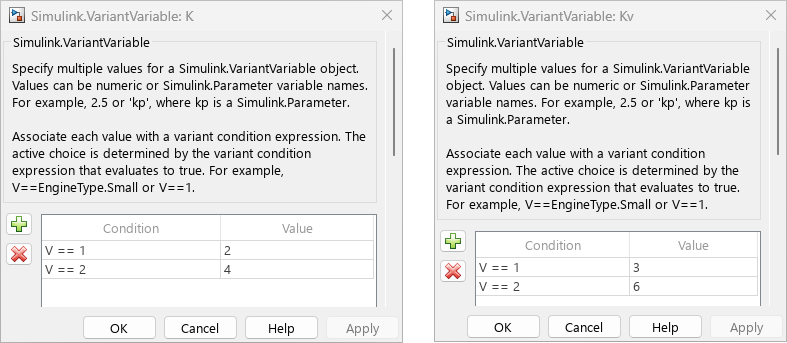
Simulink.VariantVariable dialog box shows the variant conditions and values for the variant parameters K and Kv.

When you protect the model that uses these variant parameters by using Protected Model Creator (Simulink Coder), select V as a tunable parameter for simulation to configure K and Kv as tunable.
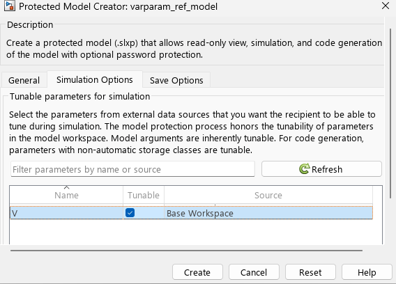
Simulation Options tab in the Protected Model Creator window shows the variant control V selected.

When you protect the model using the Simulink.ModelReference.protect (Simulink Coder) function, specify the Simulink.VariantControl objects by using the TunableParameters (Simulink Coder) name-value argument.

Simulink.ModelReference.protect(modelName,TunableParameters=["V"]);

When you get the list of tunable parameters for such a protected model using the Simulink.ProtectedModel.getTunableParameters (Simulink Coder) function, the function returns only the Simulink.VariantControl objects that you specified as tunable parameters.

The Simulink.ModelReference.protect function reports a warning if the specified variant control has a variant activation time other than startup.

Project and File Management

Comparison Tool: Save comparison reports as PDF/A file

Starting in R2026a, you can save comparison reports as a PDF/A file interactively and programmatically. PDF/A comparison reports are not supported on Linux. For more information, see Export, Print, and Save Model Comparison Results and visdiff (MATLAB).

Determine if file contains System Composer block diagram, Simulink test harness, or Subsystem block without loading file

The Simulink.MDLInfo has new properties to determine which type of model file a file without loading the file.

  • Use the SimulinkSubdomain property to find if the file contains a Simulink model or a System Composer block diagram without loading the file.

  • Use the IsTestHarness property to determine if the model file contains a Simulink test harness.

  • Use the IsSubsystem property to determine if the model file contains a Subsystem block.

Compare template to blank model template

You can now compare your model templates to the blank model template directly from the Simulink Start Page. For more information, see Compare Template to Blank Model Template.

Simulink Editor prompts when model is created using non-default built-in blank template

When you create a new model from the Simulink Stat Page using a built-in blank template that is different than the default Blank Model template, the Simulink Editor now informs you about the differences and provides a hyperlink to inspect differences. Clicking on the hyperlink launches an SLTX comparison to view the configuration settings differences between the templates.

Data Management

 Improved comparison and merge for Simulink data dictionaries

Starting in R2026a, Simulink provides improved side by side comparison and merging of data dictionaries using the Comparison Tool and adds support for resolving conflicts in data dictionaries using the Three-Way Merge Tool.

By using these tools, you can:

  • Clearly highlight changes, conflicts, and merge choices for Design Data and Architectural Data sections of data dictionaries.

  • More easily visualize differences between dictionaries and merge choices in the context of other, unchanged elements.

  • Using the Three-Way Merge Tool, manually select which version of each change you want in the target file.

To programmatically publish comparison reports for data dictionaries and to automate report generation for continuous integration (CI) workflows, use the visdiff function:

comparison = visdiff(slddFile1,slddFile2);
file = publish(comparison);
web(file)

For more information on data dictionary file comparison, see View and Revert Changes to Dictionary Data.

Signal Editor: Block and tool synchronization

The Open Signal Editor button in the Signal Editor block now opens a version of the Signal Editor tool that is synchronized with the Signal Editor block. In releases prior to R2026a, all instances of the Signal Editor tool had the same characteristics. For more information, see Differences Between the Signal Editors.
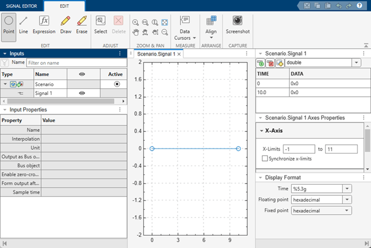
Signal Editor block default

The block version of the Signal Editor tool has these changes:

  • When you click Open Signal Editor, the Signal Editor tool now opens populated with the active scenario. The active plot shows the last signal in the scenario.

  • A new Active column in the hierarchy shows the active scenario for the block. To change the active scenario, click the associated button.

  • New input properties support the corresponding block parameters.

    Signal Editor BlockSignal Editor Interface

    Output as bus object

    Output a bus signal

    Bus object

    Select bus object

    Enable zero-crossing detection

    Enable zero-crossing detection

    Form output after final data value by

    Form output after final data value by

    Sample time

    Sample time

    Note

    The Interpolate data and Unit parameters of the Signal Editor tool are only reflected in the Signal Editor block when the block parameter Use properties from is set to Signal data in MAT file.

  • To change the active scenario in the Signal Editor tool, click the associated button in the hierarchy Active column, and then click Save. Closing the tool updates the Signal Editor block.

  • Block parameters become read-only when you open the Signal Editor tool. To change control from the Signal Editor tool to the Signal Editor block, close the Signal Editor tool.

  • To see parameter changes for an active signal from the Signal Editor block in the associated Signal Editor tool, click the active signal in the signal hierarchy.

Signal Editor: Updates

The Signal Editor has these updates:

  • The tool now supports multisignal and multiscenario selections in the Inputs signal hierarchy pane:

    • Select all signals with same name under all scenarios

    • Select all signals under same scenario

    • Select all scenario children

    • Select all scenarios

  • The tool has smoother selection and move point actions. You can now click and drag a point on the canvas. Prior to R2026a, to select and move a point, you clicked and released the point, and then clicked and dragged it.

  • The Supported File Types table has a new column, File Extension, that lists the file extensions supported by the respective import file type.

Programmatically compare model configuration sets

With R2026a, you can programmatically compare the parameter values in two model configuration sets by using the new isequal function for their two Simulink.ConfigSet objects. The function indicates whether the configurations are equal and, if they are not, returns a list of parameters that differ between the configurations. For more information, see Compare Simulink Model Configuration Parameter Values.

Type Editor enhancements to align with Interface Editor

To aid the transition between the docked Type Editor and Interface Editor as you navigate between Simulink models and architecture models, the Type Editor supports new functionality and has updated button icons.

  • When you create a type, you can enter a new name right away. In previous releases, you must double-click the default name to enter a new name.

  • To sort types, you can now click individual column headers. In previous releases, the Type Editor does not support sorting.

  • When you specify a bus object in the Type column, the Type Editor displays the bus hierarchy regardless of whether you include the Bus: prefix. In previous releases, the bus hierarchy displays only when you include the Bus: prefix.

  • When you rename a bus object, the Type Editor updates any references to the bus object in other bus objects. The Type Editor does not update references to the bus object in value types.

  • The Link external sources button has a new icon . The former Link external sources icon is now used by the Open standalone Type Editor button . This change aligns the button icons used by the Type Editor and the Interface Editor for similar actions. In previous releases, the Open standalone Type Editor button has a different icon .

For more information, see Type Editor and Interface Editor (System Composer).

 Functionality being removed or changed

Avoid overwriting data dictionary files that have changed since last load

Behavior change

Starting in R2026a, when you save a data dictionary file (.sldd) in Model Explorer that changed on disk since it was last loaded, Simulink provides these options:

  • Keep both — Simulink creates a copy of the data dictionary file on the disk, appending the filename of the copy with a suffix that you provide. Simulink then overwrites the original with your changes.

  • Overwrite — Simulink saves your changes and overwrites the data dictionary file on the disk with your changes.

  • Reload — Simulink discards your changes and reloads that data dictionary from the file on the disk. If the data dictionary is in a hierarchy of other data dictionaries, those dictionaries are also reloaded from the disk.

  • Cancel — Simulink does not save your changes.

You can also specify these options when saving a data dictionary from the command line by using the saveChanges function.

Previously, if the data dictionary file had changed on disk since the data dictionary was last loaded, your changes would overwrite the data dictionary file without notification.

For more information on Simulink data dictionaries, see What Is a Data Dictionary?

Model configuration set in data dictionary not allowed access to data in dictionaries not referenced by the dictionary containing the configuration set

Behavior change

In a Simulink data dictionary hierarchy, a model configuration set contained in a dictionary can no longer access data stored in another dictionary that is it not directly or indirectly referenced by the dictionary containing the configuration.

Regular expression support removed from Configuration Parameters dialog box search

The search box in the Configuration Parameters dialog box no longer supports regular expressions.

Block behavior depends on frame status of signal parameter removed from Configuration Parameters dialog box

Errors

The Block behavior depends on frame status of signal parameter inside the Diagnostics > Compatibility category of the Configuration Parameters dialog box has been removed.

Block Enhancements

 Enhanced C++ language support for C Function block

Starting in R2026a, the C Function block addresses the limitations mentioned in C and C++ Language Limitations and Limitations which were previously applicable to locally specified C and C++ custom code. To specify custom code locally, the Configure custom code settings Gear icon. parameter must be set to Use Block Custom Code.

Blockset Designer updates

In Blockset Designer, you can now change the implementation block name directly in the Implementation Block Name text box. In releases prior to R2026a, you had to click the Edit button to edit the implementation block name. For more information, see Change Implementation Block Name.

Model time variant linear implicit systems using Descriptor State-Space blocks

You can now model time variance in linear implicit systems using the Descriptor State-Space block by tuning the E, A, B, C, and D parameters during simulation.

The pattern of the mass matrix must remain fixed. When you tune the E parameter during simulation, only elements that have nonzero values in the initial matrix are tunable.

The values you can specify when you tune the A, B, C, and D parameters depend on whether you specify the initial value as a sparse or full matrix and the value of the new Parameter tunability parameter.

To tune these parameters using the Parameter Writer block, specify the parameters as full matrices.

Tune Data parameter of From Workspace blocks without rebuilding rapid accelerator simulation target

Tuning the Data parameter of From Workspace blocks no longer requires rebuilding the rapid accelerator simulation target. As a result, you can tune the parameter in rapid accelerator simulations that disable the up-to-date check and in applications deployed using Simulink Compiler.

To tune the Data parameter of a From Workspace block without rebuilding the rapid accelerator simulation target:

  1. Define the parameter value as a variable.

  2. Create a Simulink.SimulationInput or Simulation object to configure the simulation.

  3. Tune the parameter value using the setVariable function.

These requirements and limitations apply:

  • Tuned values must have the same format, numeric data type, complexity, and dimensions as the value of the parameter used to build the simulation target.

  • The variable used to define the Data parameter must not define any other parameters in the model.

  • Tuning input data for a bus or an array of buses is not supported.

  • Tuning the Data parameter is not supported for From Workspace blocks inside referenced models.

Change bus element port or function port associated with block

Editing the port name in an In Bus Element, Out Bus Element, Function Element Call, or Function Element block label can now assign the block and its element to a different port. Suppose your model has an input port named MyPort. You add an In Bus Element block, which corresponds with the default port, InBus. To associate the new block with MyPort instead of InBus, in the block label, double-click InBus and enter MyPort.

For more information, see In Bus Element, Out Bus Element, Function Element Call, or Function Element.

Bus Creator and Bus Selector block dialog boxes open and refresh faster

Both opening and refreshing a Bus Creator or Bus Selector block dialog box are faster in R2026a than in R2025b.

In R2025b, opening these dialog boxes for a large bus hierarchy might seem to make Simulink hang. In R2026a, these dialog boxes open faster, displaying a busy overlay while the bus hierarchy loads.

For example, create a bus hierarchy with 500 levels of hierarchy and 501 leaf elements.

% Open new model
mdl = "BusBlockPerformance";
new_system(mdl)
open_system(mdl)

% Create first bus
add_block("simulink/Sources/Constant",mdl+"/Constant");
add_block("simulink/Sources/Constant",mdl+"/Constant1");
add_block("simulink/Signal Routing/Bus Creator",mdl+"/Bus Creator");
add_line(mdl,"Constant/1","Bus Creator/1");
add_line(mdl,"Constant1/1","Bus Creator/2");

% Create bus hierarchy
prev_bus_blk = "Bus Creator";
for i = 1:499
    constant_blk = "Constant"+num2str(i+1);
    bc_blk = "Bus Creator"+num2str(i);
    add_block("simulink/Sources/Constant",mdl+"/"+constant_blk);
    add_block("simulink/Signal Routing/Bus Creator",mdl+"/"+bc_blk);
    add_line(mdl,constant_blk+"/1",bc_blk+"/1");
    add_line(mdl,prev_bus_blk+"/1",bc_blk+"/2");
    prev_bus_blk = bc_blk;
end

% Create and connect Bus Selector block
add_block("simulink/Signal Routing/Bus Selector",mdl+"/Bus Selector");
add_line(mdl,prev_bus_blk+"/1","Bus Selector/1");

The code to open and close the Bus Creator block dialog box for the top-level bus is about 2.2x faster than in the previous release.

function timingTestBusCreator
open_system("BusBlockPerformance/Bus Creator499");
close_system("BusBlockPerformance/Bus Creator499");
end

The approximate execution times are:

  • R2025b: 1.7 s

  • R2026a: 0.78 s

The code to open and close the Bus Selector block dialog box for the top-level bus is about 2.3x faster than in the previous release.

function timingTestBusSelector
open_system("BusBlockPerformance/Bus Selector");
close_system("BusBlockPerformance/Bus Selector");
end

The approximate execution times are:

  • R2025b: 1.8 s

  • R2026a: 0.79 s

The code was timed on a Windows 11, AMD EPYC 74F3 @ 3.19 GHz test system using the timeit function:

timeit(@timingTestBusCreator)
timeit(@timingTestBusSelector)

Scale magnitude of Complex to Magnitude-Angle block

To scale the magnitude of the Complex to Magnitude-Angle block by a factor of (1/CORDIC gain), select the Scale output by reciprocal of gain factor parameter.

Multiport Switch, Index Vector, Switch, and MinMax block select efficient output data type

The Multiport Switch (Simulink), Index Vector (Simulink), Switch (Simulink), and MinMax (Simulink) blocks have new Output data type inherit options to help select efficient output data types.

For more predictable output data type selection and control over selection priority, consider using the new Inherit: Keep MSB and Inherit: Keep LSB options instead of Inherit: Inherit via internal rule. For an algorithm that heuristically balances range and precision, consider using Inherit: Inherit via internal rule, which can cause undesired results.

Trigonometric Function block update

Starting in R2026a, the Trigonometric Function block algorithm has changed when the block has these settings.

Block ParameterSetting

Function

One of:

  • sin

  • cos

  • sincos

  • cos+jsin

Approximation method

Lookup

Angle unit

radian

For floating- and fixed-point data types in both simulation and code generation, the block now replaces calculations of u/(2*pi) with u*(1/(2*pi)).

  • In releases prior to R2026a, some intermediate results were stored in fixed-point data types equivalent to fixdt(0,WL,WL-3), where WL is the word length.

  • Starting in R2026a, some intermediate results are now stored in fixed-point data types equivalent to fixdt(0,WL,WL+2), where WL is the word length.

Existing models might experience a small output difference on the order of 10-16.

Neighborhood Processing Subsystem block supports custom output size

Before R2026a, the Neighborhood control block for the Neighborhood Processing Subsystem supported only these settings for the Output size parameter:

  • Same: The output matrix has the same dimensions as the input matrix.

  • Full: The output matrix is larger than the input matrix and contains an element for each neighborhood that includes at least one unpadded value from the input matrix.

  • Valid: The output matrix is smaller than the input matrix and contains elements for only the input matrix elements whose neighborhoods did not contain padded values outside the input matrix.

Starting in R2026a, you can generate other output sizes from the Neighborhood Processing Subsystem block. The Neighborhood block parameter Output size supports a new value, Custom, which enables a new Neighborhood block parameter, Padding size.

The Padding size parameter accepts a vector of nonnegative scalars that define the amount of padding for the start and end, respectively, of each dimension of the input matrix. For example, for a 2-dimensional input matrix, provide a vector of the form [a b c d] where each element is a nonnegative scalar. a defines the amount of padding at the start of the first dimension, b defines the amount of padding at the end of the first dimension, c defines the amount of padding at the end of the second dimension, and d defines the amount of padding at the end of the second dimension.

The following screenshot demonstrates the parameter behavior by passing a 5-by-5 matrix through Neighborhood Processing Subsystem blocks that have different padding sizes. Each subsystem uses a 1-by-1 neighborhood and returns the input value without modifying it. For the padded values, each subsystem uses the constant value 0.

Model that passes a 5-by-5 matrix through three Neighborhood Processing Subsystem blocks. Each element of the input matrix contains the value 1. The first subsystem has a padding size of "[0 0 0 0]" and produces a copy of the input matrix. The second subsystem has a padding size of "[1 0 2 0]" and returns a matrix that contains a row of zeros and two columns of zeros above and to the left of the input matrix. The third subsystem has a padding size of "[0 1 0 2]" and returns a matrix that contains a row of zeros and two columns of zeroes below and to the right of the input matrix.

Use custom padding sizes to configure the dimensions of the output data in image processing tasks.

Step block programmatic name updates

These Step block programmatic names have changed.

Previous NameNew Name
BeforeInitialValue
AfterFinalValue

Existing applications continue to work.

 Adding Signal Builder block to model warns

The Signal Builder block is no longer recommended. Use the Signal Editor block instead.

 Compatibility Considerations

For more information about the warning, see Adding Signal Builder block warns.

C Caller Block: Observe custom code global variables wirelessly using observers

Starting in R2026a, you can observe exported global variables used by a C Caller block using the Observer Port (Simulink Test) and the Observer Reference (Simulink Test) blocks. You can verify and validate those global variable values used in your external custom code without exposing these variables as C Caller block output in the main model. To use the observers, you must have a Simulink Test license. For more information, see Access Model Data Wirelessly by Using Observers (Simulink Test).

C Caller Block: Use dialog box buttons to add or delete global variables

Starting in R2026a, you can use the C Caller block dialog box buttons Add and Remove to add global variables from custom code or delete global arguments from the block, respectively. To automatically infer global variables from the custom code using the block dialog box, use the Magic wand button.

If block enhancements

Starting in R2026a, the If block uses a new parser that allows you to:

  • Modify the If block input port labels to meet your modeling requirements. This change allows you to tailor the logical expressions within the block using custom names. Previously, you could only use the default names such as, u1, u2, and so on for inputs.

    The default port label u1 of the If block is changed to a new label sig1.

  • Use a range of logical expressions that were not previously supported, including expressions that use:

    • Tunable parameters.

    • General MATLAB expressions, such as x1 > x2 + 5.

    • Data objects such as Simulink.Parameter, Simulink.Signal with custom storage classes. For more information, see Create and Apply Storage Class Defined in User-Defined Package (Embedded Coder).

    • Fixed-point data type.

    • Enumerated data type.

    • MATLAB structure arrays.

    • Expressions with:

      • Arithmetic functions — ceil, floor, abs, and sign.

      • Trigonometric functions — sin, cos, tan, asin, acos, atan, atan2, sinh, cosh, and tanh.

      • Exponential, logarithmic and root functions — log, log10, exp, and sqrt.

These capabilities are not supported for the Model Slicer tool in Simulink Check.

Discrete FIR Filter Block: Generate SIMD code for direct form transposed filter structure

Generate SIMD code for the Discrete FIR Filter block when you set the filter structure to Direct form transposed by using the model configuration parameter Leverage target hardware instruction set extensions. For more information, see Code Generation.

To generate SIMD code from the Discrete FIR Filter block, you must have an Embedded Coder license.

Discrete FIR Filter Block: Improved simulation speed for direct form transposed filter structure

The simulation speed of the Discrete FIR Filter block has improved when you set the Filter structure to Direct form transposed. You can see the improvement in simulation speed when the block:

  • Simulates in Normal mode

  • Simulates in Accelerator mode

  • Simulates in Rapid Accelerator mode

  • Belongs to a model reference and operates in Normal mode

  • Belongs to a model reference and operates in Accelerator mode

Discrete FIR Filter Block: Generate memory-efficient code

Generate memory-efficient code from the Discrete FIR Filter block when you set these parameters:

  • Filter Structure to Direct form

  • Input processing to Columns as Channels (frame based)

For more information, see Generate memory-efficient code in the Discrete FIR Filter block reference page.

Programmatically control cursors and get descriptive statistics for signals in the Record block and Playback block

Starting in R2026a, you can programmatically add and position cursors on plots in the Record block and Playback block. For example, add two cursors to the Playback block and position the cursors at 3 and 7 seconds.

set_param("MyModel/Playback","ShowCursor",2)
set_param("myModel/Playback","CursorPositions",[3,7])

You can also get descriptive statistics for signals in the Record and Playback blocks using the new signal ID parameter. To get a set of descriptive statistics for a signal using the signal ID, use Simulink.analytics.getMetrics. To get a single descriptive statistic, use Simulink.sdi.Signal object functions such as max and min.

pbSigIDs = get_param("myModel/Playback","SignalIDs");
>> sigStats = Simulink.analytics.getMetrics(pbSigIDs(1))
sigStats = 

  struct with fields:

           min: -0.9962
           max: 0.9996
    peakToPeak: 1.9957
          mean: 0.1744
        median: 0.3115
           std: 0.6704
           rms: 0.6863

To focus your analysis on a specific time range, combine cursor placement and signal statistics. Define the time span with cursors set either programmatically or interactively. To analyze signal statistics within this time span, use get_param to retrieve the cursor positions. Then use the positions as the start and end times in Simulink.analytics.getMetrics.

sigBounds = get_param("myModel/Playback","CursorPositions");
sigStats = Simulink.analytics.getMetrics(pbSigIDs(1),sigBounds(1),sigBounds(2))
sigStats = 

  struct with fields:

           min: -0.9962
           max: 0.6570
    peakToPeak: 1.6532
          mean: -0.3948
        median: -0.4646
           std: 0.5189
           rms: 0.6421
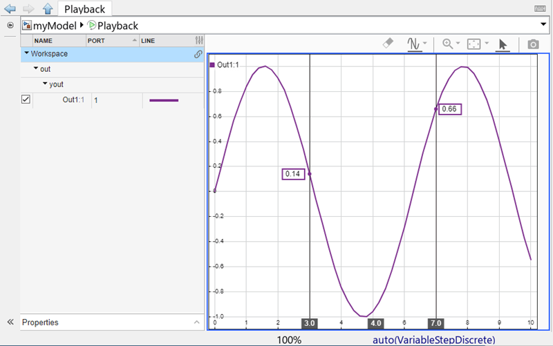
Playback block showing a sine wave with cursors at 3 and 7 seconds.

Add blocks to dashboard panels using quick insert menu

Dashboard panels are virtual dashboards to which you can add blocks from the Dashboard library (including the Customizable blocks library) or the Aerospace Blockset™ library. The panels float above the model canvas and follow you through the model hierarchy. Starting in R2026a, you can add blocks to dashboard panels using the quick insert menu.

To do so, enter edit mode. First, select the panel. Then, in the Simulink Toolstrip, on the Panels tab, click Edit Panels. If needed, resize the panel to make the panel big enough to hold the block you want to add by dragging the panel edges outward. Adding blocks that are bigger than the panel is not supported.

To add the block, double-click where you want to add the block. You must click a blank space on the panel. The quick insert menu appears. Start entering the name of the block you want to add. Select the block you want to add in the list of search results. The new block appears in the panel.

For more information about dashboard panels, see Getting Started with Dashboard Panels.
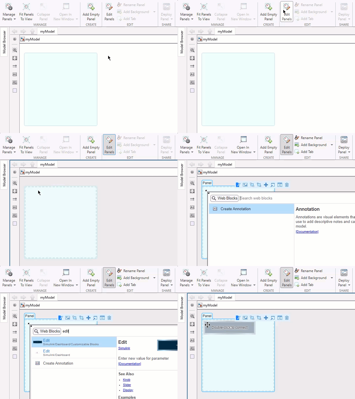
A model contains a blank dashboard panel. An Edit block from the Customizable Blocks library is added to the panel using the quick insert menu.

Use the customizable Edit block to change parameter or variable values

The Edit block connects to a parameter or variable value in your model. You can change the connected value before or during simulation by entering a new value in the edit box. When you use the version of the Edit block in the Customizable Blocks library, you can customize the appearance of the block to look like an edit box in an existing digital interface.

  • Choose from a list of WYSIWYG (what you see is what you get) fonts that look the same on all platforms.

  • Change the font size.

  • Change the text color.

  • Make the text bold, italic, or underlined.

  • Change the text position within the block.

  • Add a background image or choose a background color.

  • Add a foreground image.

Use the Edit block with other dashboard blocks to build an interactive dashboard of controls and indicators for your model.

Edit block with the number 42 entered in the edit box

Programmatically switch dashboard panel tabs

Dashboard panels can have multiple tabs. You can now programmatically switch which tab a panel displays using the simulink.dashboard.switchPanelTab function. For example, you can use this capability to create a dashboard that switches tabs when you click a button by entering the simulink.dashbaord.switchPanelTab function in the callback function that runs when you click the button.

simulink.dashboard.switchPanelTab(model,tab)

model is the handle or name of the top-level model containing the tab to which you want to switch. Specify the handle as a scalar, and the name as a string or character array. For information about how to get a model handle, see Get Handles and Paths. tab is the name of the tab to which you want to switch, specified as a string or character array. To use the simulink.dashbaord.switchPanelTab function, the model you specify in the input arguments must be open. Loading the model is not sufficient.
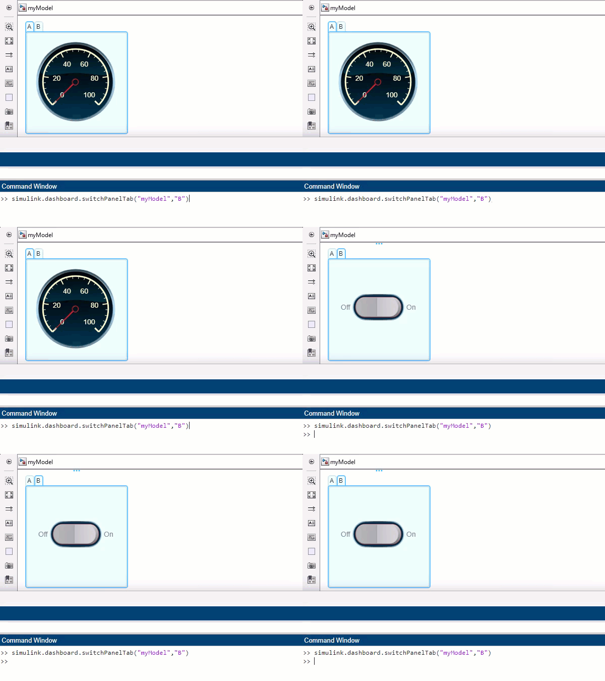
The model named myModel contains a dashboard panel with two tabs, respectively named A and B. The panel displays tab A. The command simulink.dashboard.switchPanelTab("myModel","B") is entered in the command window. The panel displays tab B.

Programmatically check whether a block is a dashboard block

Dashboard blocks are blocks from these libraries:

  • Dashboard library (including the Customizable Blocks sublibrary)

  • Aerospace Blockset library

You can now programmatically check whether a block is a dashboard block using the simulink.dashboard.isDashboardBlock function.

tf = simulink.dashboard.isDashboardBlock(block)

block is the block handle or block path. For information about how to get a block handle or path, see Get Handles and Paths.

If the block is a dashboard block, the function outputs 1. If not, the function outputs 0.

Use bulk clipboard operations on mask parameters

Starting in R2026a, you can select multiple parameters from Mask Editor and use keyboard shortcuts or mouse pointers for clipboard operations. You can use bulk clipboard operations within the same mask or across multiple masks, which is helpful when you deal with large scale mask definitions. Bulk clipboard operations preserve the properties of the mask parameters, such as constraints and default values. Simulink retains callbacks associated with the mask parameter, if you save them within the mask. However, Simulink does not retain callbacks when you save them in a separate callback file.

Mask Editor: Enhanced constraint manager user interface to manage constraints

Starting in R2026a, you can define and manage all types of parameter and port constraints by using the enhanced Constraints tab in Mask Editor.

Enhancements to the Constraints tab include:

  • Add all types of parameter and port constraints from the Constraint Gallery panel on the left side of the Constraints tab instead of selecting the constraint type from the toolstrip.

  • Simulink displays predefined constraints, called as Commonly Used Constraints, in the Constraint Browser panel. You can associate these constraints with mask parameters without creating them manually.

  • To avoid unintended changes, shared constraint files are locked. To modify a shared constraint file, click Edit File on the toolstrip.

  • Associate parameters and ports to their respective constraints by using the Associations section of the Constraints tab. Previously, you associated constraints to parameters from the Parameters and Dialog tab.
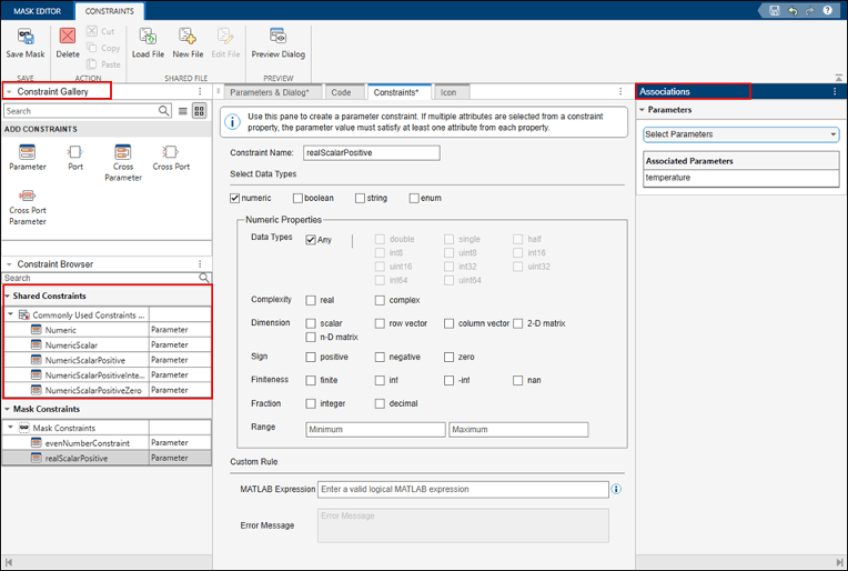
Constraint manager displays a parameter constraint associated to a parameter temperature

For more information, see Author Parameter and Port Constraints Using Standalone Constraint Manager.

MATLAB System properties are validated in the mask dialog box when focus moved to another control

MATLAB System properties with validation functions such as mustBeNonpositive and mustBeMember are validated in the mask dialog box of a MATLAB System block when focus is moved to another control.
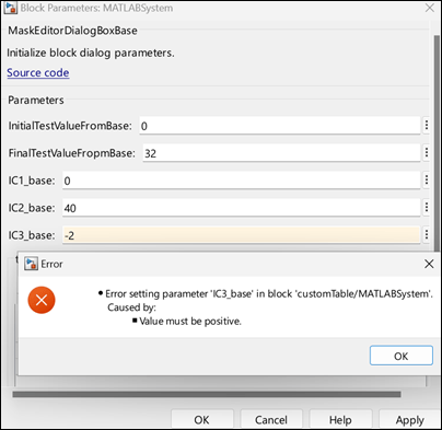
Mask dialog box of a MATLAB System block. An error is displayed when the parameter IC3_base is set to a negative value.

Use fully qualified name to invoke custom functions in a mask callback file

When you save a mask callback file with a model, use the fully qualified names to invoke custom functions. If the callback file resides in a folder within the model, to avoid path-related errors, reference the function with its full path. For example, if the name of the model is engine.slx, the mask callback is vehicles.m, and the custom function name is calculateForce, then invoke the function as engine.vehicles.calculateForce() in the mask callback file.
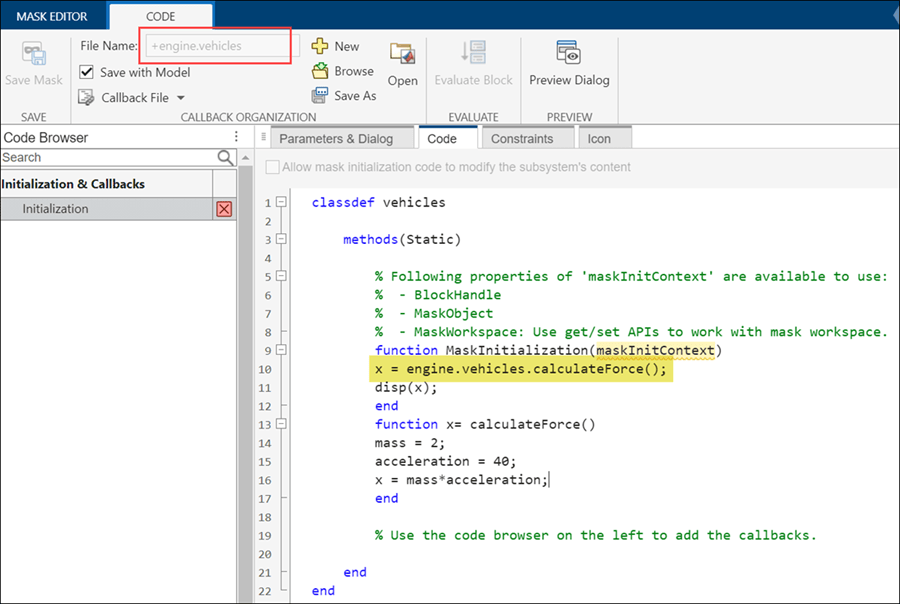
Code tab of the Mask Editor displaying callback saved in a callback file.

Enhancements to Graphical Icon Editor

Graphical Icon Editor has these enhancements:

  • Default authoring mode for block icons — Graphical Icon Editor is now the default authoring mode to design masked block icons. To switch to mask drawing commands, in the Authoring Mode section of the toolstrip, click Graphical and then select Drawing Commands.

  • Customize shape of block frame — To customize the shape of the block frame, in the Icon Properties pane go to the Transform section, and select a shape from the Frame list. Click edit icon to modify the frame as desired and then click close button. Preview the icon in Simulink to view the modified block frame.

  • Quick insert element shapes — Search for and insert shapes on the canvas. Double-click the icon canvas and type the name of a shape. A drop-down list of available shapes appears in the drop-down list. Select a shape from the list to insert it into the canvas. Alternatively, in the Tools pane, select Shape Finder to search and insert shapes.

  • Add port labels to block icons — To specify a port label, in Tools pane, select Port Label.

  • Properties pane enhancements — Updates to the Icon Properties, Element Properties and Text Properties panes make it easier to navigate and set various properties. You can also automatically generate port labels and associate parameters and expressions with text elements.

For more information, see Graphical Icon Editor Overview.
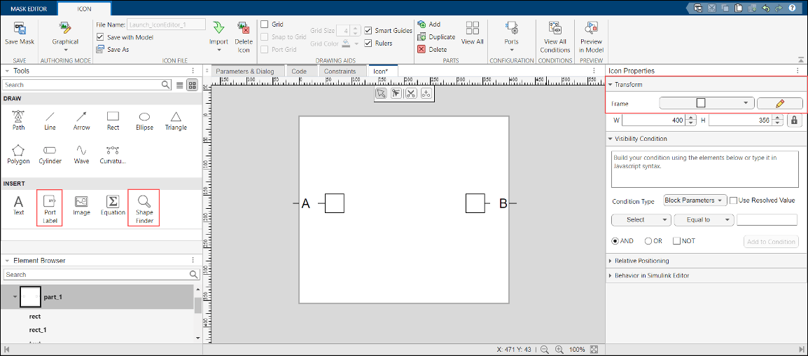
View of Graphical Icon Editor

Define block mask type in a MATLAB System class

Starting in R2026a, you can use the Type property of matlab.system.display.Header class to specify the type of block mask in a MATLAB System class. The type property helps you to identify blocks having a specific mask type within a model.

For example, you can set the mask type of a block to Aero and filter blocks having mask type set as Aero. For more information, see matlab.system.display.Header.

Display mask parameters in a nested structure using the Parameter Tree container

Use the Parameter Tree container in the Mask Editor to display mask parameters in a nested structure. The Parameter Tree container supports Group Box containers and Edit, Check Box, Popup, and Combo Box parameters.
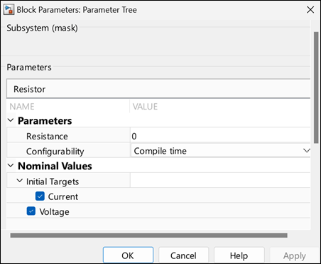
Parameter tree displaying parameters in a nested structure.

For more information, see Use Mask Containers to Group Parameters on Mask Dialog Box. To programmatically create and group mask parameters in a parameter tree container, use methods of Simulink.dialog.ParameterTree class.

Associate predefined constraints with mask parameters

Starting in 2026a, Simulink displays predefined constraints in the Constraints tab of the Mask Editor. You can associate these constraints with mask parameters without creating them manually. These constraints are available only for the Parameter Constraint type. The available constraints include:

  • Numeric

  • NumericScalar

  • NumericScalarPositive

  • NumericScalarPositiveInteger

  • NumericScalarPositiveZero

Constraints tab of the Mask Editor. The predefined constraint NumericScalarPositive is applied to a mask parameter.

The predefined constraints are read-only, and you cannot modify their rules. To associate a constraint with a mask parameter, select the parameter from the Associations section.

For more information, see Use Port Constraints to Validate Input and Output Signals.

Customize custom table parameter in MATLAB System block

To customize a custom table parameter within a MATLAB System block, use the matlab.system.display.Table class in the System object™ class definition file. You can specify the column type as Edit, Popup, or Check Box. For Popup column type, use the TypeOptions property to list the Popup options. Additionally, you can set the Evaluate option for the column to evaluate any MATLAB expression present in the cell.

For more information, see Create Table Parameter for MATLAB System Block.

Banner notification to synchronize System object mask definition XML file

When you modify a MATLAB System class associated with a MATLAB System block, the corresponding mask definition XML file can become outdated. Starting in R2026a, when you modify a MATLAB System class, a notification banner prompts you to open the Mask Editor and perform Save Mask. This action updates the mask definition in the XML file.

Notification on a stale mask customization

 Functionality being removed or changed

Adding Signal Builder block warns

Warns

The Signal Builder block is no longer recommended. Adding the Signal Builder block to a model now returns a warning:

Warning: Signal Builder block will be removed in a future release.

Old lookup table blocks being removed

The obsolete versions of these blocks will be removed in a future release. Use the listed replacement blocks instead.

Obsolete BlockReplacement Block

PreLookup Index Search

Prelookup

Interpolation (n-D) Using PreLookup

Interpolation Using Prelookup

Lookup Table

1-D Lookup Table

Lookup Table (2-D)

2-D Lookup Table

Existing models will continue to run until removal.

S-Function blocks will no longer support non-contiguous inputs

Still runs

Starting in R2026a, S-Function blocks support only contiguous inputs. Contiguous input functions provide faster access and improved performance by removing the need for a double pointer to access signals. It is recommended to use the ssSetInputPortRequiredContiguous function to specify input signal type and then access input signals by using the contiguous input functions ssGetInputPortSignal and ssGetInputPortRealSignal instead of ssGetInputPortSignalPtrs and ssGetInputPortRealSignalPtrs, respectively.

Three Dashboard library blocks will be replaced with equivalents from Customizable Blocks library

Behavior change in future release

The Rocker Switch, Slider Switch, and Toggle Switch blocks in the Dashboard library will be replaced with their more customizable equivalents from the Customizable Blocks library in a future release. The new blocks will look the same as the blocks they replace and behave the same in the model. The options for configuring and customizing the blocks will change. The block types will also change.

Block Parameters dialog box table for connecting dashboard blocks will be removed

Still runs

In a future release, connecting blocks from the Dashboard library or the Customizable Blocks library using the table in the Block Parameters dialog box will no longer be supported. Use connect mode instead. For information about connect mode, see Connect Dashboard Blocks to Simulink Model.

Imported and exported type handling in C Function block

Behavior change

  • Imported type handling — Starting in R2026a, if you do not have a header file available with simulation-compatible type definitions for imported enumerated, bus, or alias types, the block cannot resolve these types and issues an error. To resolve this error, select the Imported type headers are not available for simulation parameter in the C Function block dialog box.

    Previously, if the C Function block could not find type definitions for enumerated, bus, or alias types, the block would automatically generate the type definitions for simulation purposes.

  • Exported type handling — Starting in R2026a, if you specify header files containing type definitions for enumerated, bus, alias types for simulation while that type is exported, you might receive a parser error indicating that the types are already defined. To resolve this error, select the Exported types are defined in simulation custom code headers parameter in the C Function block dialog box.

    Previously, if the C Function block was able to find the type definition for enumerated, bus, or alias types, the block did not regenerate type definitions for simulation.

Connection to Hardware

Support model referencing for driver blocks on Arduino hardware

Starting R2026a, you can use all the driver blocks from Simulink Support Package for Arduino Hardware library inside a model reference. A model reference is a reference to another model using a Model block. These references create model hierarchy and each referenced model has a defined interface that specifies the properties of its inputs and outputs.

For more information on how to use model referencing with Arduino driver blocks in Simulink, see Model Reference Support for Arduino Driver Blocks in Simulink.

Detect state of touch pins on Arduino-compatible ESP32 hardware

This release introduces the ESP32 Touch Sense block for Simulink Support Package for Arduino Hardware. You can use the built-in 10-channel capacitive touch sensor module on the ESP32 board to sense the state of capacitive touch pins on Arduino-compatible ESP32 WROOM and WROVER boards. The block also provides a raw sensor value that represents the capacitance value at the pin you touch.

For more information on capturing images using the ArduCam OV2640 camera module with Arduino-compatible ESP32 hardware, see Capture Images with Touch Sense Using ArduCam OV2640 Camera Module and Arduino Compatible ESP32 Hardware.

Support for handling serial interrupt on Arduino SAMD hardware

Starting R2026a, Simulink Support Package for Arduino Hardware supports handling serial interrupts for the SAMD family of Arduino hardware. The support package introduces Serial Receive and Serial Transmit blocks that supports serial communication interface (SERCOM) interrupt handler. You can access these new blocks from the Advanced > SAMD library.

For more information on configuring SERCOM properties, see Sercom properties. For more information on implementing motor speed control using IMU data and SERCOM serial interrupts on Arduino, see IMU-Based Motor Speed Control on Arduino Using SERCOM Serial Interrupts.

Support added for ThingSpeak and MQTT on Arduino UNO R4 Wi-Fi hardware

Starting R2026a, Simulink Support Package for Arduino Hardware supports deploying a Simulink model containing these blocks on Arduino UNO R4 Wi-Fi board:

Support added for built-in LED Matrix on Arduino UNO R4 Wi-Fi hardware

Starting R2026a, Simulink Support Package for Arduino Hardware introduces the 12x8 LED Matrix block to configure and control the 12x8 built-in LED matrix on Arduino UNO R4 Wi-Fi board. You can use this block to display graphics. To create a frame to illuminate a target pixel on the built-in LED, use the 12x8 Matrix block and check individual check boxes.

Support added for BLE on Arduino UNO R4 Wi-Fi and Nano RP2040 Connect hardware

Starting R2026a, Simulink Support Package for Arduino Hardware supports deploying a Simulink model containing BLE Send and BLE Receive blocks on Arduino UNO R4 Wi-Fi and Nano RP2040 Connect boards. You can now send and receive data using the Bluetooth® low energy (BLE) protocol on your Arduino UNO R4 Wi-Fi and Nano RP2040 Connect boards.

For more information on configuring BLE properties, see BLE properties.

Support for on-board CAN on Arduino UNO R4 hardware

Starting R2026a, Simulink Support Package for Arduino Hardware supports deploying a Simulink model containing On-board CAN Receive and On-board CAN Transmit blocks on Arduino UNO R4 Wi-Fi and Minima boards.

Support for secure MQTT data communication on Arduino-compatible ESP32 and Raspberry Pi Pico W hardware

Starting R2026a, Simulink Support Package for Arduino Hardware supports establishing a secure MQTT connection between the server and a client using certificate-based authentication. You can now configure MQTT parameters such as specifying an SSL certificate and add a broker client key to authenticate the connection to the server.

For more information on configuring MQTT properties, see MQTT properties.

For more information on securely publishing and subscribing to messages on a Mosquitto™ broker using MQTT blocks on Arduino, see Securely Publish and Subscribe to Messages on Mosquitto Broker Using Arduino Hardware and Generate SSL/TLS Credentials for Mosquitto MQTT Broker.

MATLAB Function Blocks

Identify assumed doubles in MATLAB function report

When you do not specify a size for the output of a MATLAB Function block, Simulink assumes that input variables have type double during size propagation. Starting in R2026a, the MATLAB function report identifies these variables by using the indicator double (assumed). See MATLAB Function Reports. Use this indicator to help you to debug downstream issues in your code. For example, this indicator can help you to identify if a function passes an assumed double to a function that does not expect a double. To prevent assumed doubles, explicitly specify the sizes of all output variables.

Input Argument Validation: Use multiple repeating input arguments in non-entry-point functions

Starting in R2026a, you can use arguments (MATLAB) blocks in non-entry-point functions that contain multiple repeating input arguments. See Generate Code for arguments Block That Validates Input and Output Arguments.

In previous releases, MATLAB Function blocks supported only a single repeating input argument to a non-entry-point function.

Use handle classes that have custom copy functionality

Starting in R2026a, MATLAB Function blocks can contain MATLAB functions that use subclasses of the matlab.mixin.Copyable (MATLAB) abstract class. These subclasses inherit:

  • A public copy (MATLAB) method that makes a shallow copy of a subclass instance

  • A protected copyElement (MATLAB) method that you can override to control the copy behavior of your subclass

MATLAB Function blocks support both the copy and copyElement methods. MATLAB Function blocks also support the NonCopyable property attribute, which you can use to indicate that you do not want to copy a particular property value. See Implement Copy for Handle Classes (MATLAB).

Code generation for more toolbox functions

In R2026a, you can generate code for additional toolbox functions and objects. For a list of all functions and objects that are supported for code generation, see:

These are links to the release notes of some toolboxes that added code generation support in R2026a:

Simulink

Starting in R2026a, you can use the new coder.findOrError function to find the indices and values of nonzero elements in an array. Unlike the find function that always returns variable-length vectors in code generation, the coder.findOrError(X,n) function call returns vectors of fixed length n if n is a constant during code generation. If the array X contains fewer than n nonzero elements, coder.findOrError(X,n) produces either a compile-time or a run-time error.

Image Processing Toolbox

See C Code Generation: Generate code from additional functions using MATLAB Coder.

Signal Processing Toolbox

See Deep Learning: Code generation support for inverse short-time Fourier transform.

Statistics and Machine Learning Toolbox

See:

Wavelet Toolbox

See Deep Learning: Code generation for continuous wavelet transform.

 Functionality being removed or changed

Size propagation errors can occur due to ambiguous variable data types

Errors

As a result of improvements that support additional function use in the MATLAB Function block, if your output variables inherit their data type, the block can generate an error during size propagation. To resolve this error, explicitly define the variable data type. Set the Type property to a value other than Inherit: Same as Simulink.

Changes to generation and placement of included header files for models that contain blocks that call functions that specify header file inclusions

Behavior change

Starting in R2026a, when a model includes a MATLAB Function block, MATLAB System block, or MATLAB function in a Stateflow chart that calls the coder.cinclude or coder.ceval function to specify header files, the code generator no longer includes the specified header files in these locations:

  • By default, in the generated header file model.h.

  • In the generated header or source file for a subsystem, unless the call to coder.cinclude or coder.ceval is in that subsystem.

Previously, when a MATLAB function called coder.cinclude or coder.ceval from within a model, the header file #include statements in the generated code included header files specified in the function call, which could lead to unnecessary header file inclusions and cause compilation issues.

For more information, see Integrate C Code by Using the MATLAB Function Block and Model Configuration Parameters: Code Generation Custom Code (Simulink Coder).

R2025b

Bug Fixes

Quality and stability improvements

R2025b delivers quality and stability improvements, building on the new features introduced in R2025a.

R2025a

New Features, Bug Fixes, Compatibility Considerations

 Straighten signal lines while moving or resizing blocks

Starting in R2025a, when moving or resizing a block with three or more ports straightens a signal line that connects the block to a nearby block with one or two ports, the signal line remains straight as you continue to move or resize the block. The affected signal lines are highlighted in green. Signal lines with branches or Simscape connections are not affected.

This functionality is an extension of the functionality that, when you drag or resize a block with three or more ports, preserves existing short, straight lines that connect to blocks with one or two ports. Starting in R2025a, when you move blocks using the keyboard, the functionality is turned off.

When you move or resize blocks with your pointer, you can temporarily turn the functionality off by holding down the space bar. When you release the space bar, the functionality turns back on. To turn the functionality off across MATLAB sessions, in the Simulink Editor, on the Modeling tab, under Environment, clear Preserve Alignment. To turn the functionality back on, select Preserve Alignment.

A Subsystem block connects to three Inport and three Outport blocks with short signal lines. The signal lines connecting the Inport blocks and one of the Outport blocks are straight. The other two signal lines connecting to the Outport blocks have a bend. The block moves up, straightening one of the signal lines. The signal line remains straight as the block continues moving. The block then stretches downwards, straightening the other signal line. The signal line remains straight as the block continues to resize.

Compare diagnostic messages from different run-time operations of a model using the new Comparator

Use the Comparator in the Diagnostic Viewer to easily identify new diagnostic messages that a model generates during various run-time operations. The Comparator can compare diagnostic messages between any two operations within the same MATLAB session, across different sessions, or even across different MATLAB versions. To compare diagnostic messages from different sessions, you can save the diagnostic messages from an operation as a baseline file and import it later for comparison with diagnostic messages generated from a subsequent operation.

To use the Comparator, select Comparator from the drop-down menu on the left side of the Diagnostic Viewer.

By using the Comparator you can:

  • Compare diagnostic messages between any two run-time operations. The operations must be of similar type. For example, diagnostic messages from a simulation operation must be compared with diagnostic messages from another simulation operation.

  • View the count of the diagnostic messages that have been added and removed between operations.

  • View newly added diagnostic messages.

  • Copy the comparison report to the clipboard in text and JSON formats.
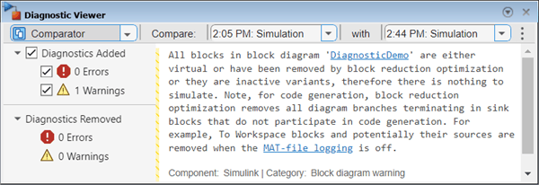
Diagnostic Viewer displaying the Comparator. At the top, there are drop-down menus for selecting simulation stages to compare. The left side displays the count of diagnostics that have been added and removed. The center pane presents the newly added diagnostic messages.

For more information on using the Comparator, see Compare Diagnostic Messages Between Model Simulations.

To programmatically compare diagnostic messages from various run-time operations of a model, use functions of sldiagviewer.DiagnosticReceiver object and sldiagviewer.Comparator namespace. For more information, see Compare Diagnostic Messages Between Model Simulations Programmatically.

Access Model Finder from Simulink Toolstrip and Start Page

In addition to using the modelfinderui function, starting in R2025a you can open the Model Finder user interface from these locations:

  • Simulink Toolstrip — In the Modeling tab, in the Evaluate & Manage section, click the down arrow next to Find and then select Model Finder.

  • Simulink Start Page — In the Learn menu, click Model Finder.

Apply search filters, customize views, and index projects using Model Finder functions

Filter search results and customize their layout by using these name-value arguments of the modelfinder function:

  • filters — Starting in R2025a, filtering search results using name-value argument blocks is not supported. Instead, use the name-value argument filters to narrow down the search results by specifying criteria such as MathWorks® product names, model locations, block types, or external referenced files. To specify filters, create a ModelFinderFilter object. For information on how to create and search using filters, see Search Models with Additional Filters.

  • view — Customize the layout of Model Finder search results. Choose between viewing results as a list of examples with their supporting models or as a list of models only. For more information, see the name-value argument view.

Additionally, when you register a folder using the modelfinder.registerFolder function and it contains a PRJ project file, Model Finder indexes the project and its models in the database.

Access Library Browser from linked blocks in models

Starting in R2025a, you can open the Library Browser directly from the context menu of a linked library block in a model. The Library Browser displays the tree view of the library containing the linked library block, with the block highlighted. This context menu option enables you to manage and browse related blocksets efficiently and is available for all libraries added to the Library Browser.
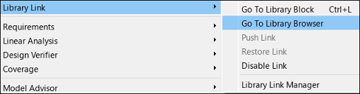
Context menu of a linked block highlighting the Go To Library Browser option.

Programmatically resize blocks to fit displayed values

These Simulink blocks display a parameter value on their block icons:

When the blocks are too small to display the full parameter value, the blocks display a placeholder letter instead, for example, -K-. A model that contains many blocks displaying placeholder letters can be difficult to work with, and resizing all the affected blocks takes time.

You can now programmatically resize blocks of the listed block types to be large enough to display their values using the Simulink.BlockDiagram.resizeBlocksToFitContent function. For example, to resize all blocks of the listed block types in a model named myModel, run this command.

Simulink.BlockDiagram.resizeBlocksToFitContent("myModel")
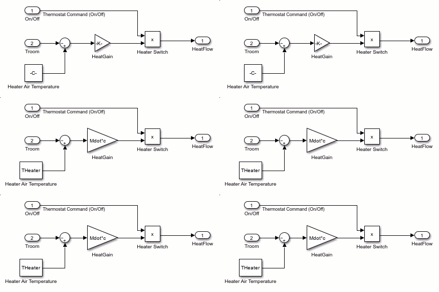
A model contains a Constant block that displays -C- and a Gain block that displays -K-. When the Simulink.BlockDiagram.resizeBlocksToFitContent function runs,

Get block paths and port paths using context menu

To programmatically edit a block or port, in the input arguments of the function you want to run, you must specify the block or port using a handle or path. A path is a string (preferred) or character vector that specifies the location of the block or port in the model hierarchy relative to the root level of the model. For example, suppose you have a model named myModel containing an Inport block and a Scope block with three ports. This command connects the port on the Inport block to the bottom port on the Scope block using the port paths "myModel/Inport/1" and "myModel/Scope/3", respectively.

Simulink.connectBlocks("myModel/Inport/1","myModel/Scope/3")

You can now get the block paths and port paths for your commands interactively. In your model, right-click a block or port and select Copy Path. Then, paste the path into your command. Remember to add quotes around the pasted text to convert the text into a string or a character vector. For more information about getting and using paths, see Get Handles and Paths.
The Matlab Command Window displays part of the command to programmatically connect the Inport block to the Scope block. The path of the bottom port of the Scope block is missing. A Simulink window appears. In the Simulink Window, the pointer right-clicks the bottom port of the Scope block and selects Copy Path. The path is pasted at the end of the command in the Matlab Command Window. The command is completed and executed. In the Simulink window, the Inport and Scope block are connected with a signal line.

Model elements you select for conversion to signal lines or Goto and From blocks can include nonconvertible model elements

Since R2024a, you can convert Goto and From blocks to signal lines, and you can convert signal lines and buses to Goto and From blocks. To perform such a conversion, select the blocks, or signal lines and buses, you want to convert. In the Simulink Toolstrip, open the Goto, From, Signal Line, or Multiple tab. In the Conversion section, click Convert to Signal or Convert to Goto/From.

In R2024a and R2024b, if the model elements you select for conversion include anything other than Goto blocks, From blocks, signal lines, and buses, or if your selection includes both blocks and signal lines or buses, or if any model element in your selection does not meet these criteria, the conversion is not supported:

  • The signal lines, buses, or blocks are fully connected.

  • The signal lines, buses, or blocks are all in the same location in the model hierarchy, meaning either all in the top level of the hierarchy or all in the same component.

  • The signal lines or buses are not connected to any Goto or From blocks.

Starting in R2025a, if any select model elements meet the criteria, you can perform the conversion regardless of whether the selection also includes additional model elements that do not meet the criteria. During the conversion process, the software ignores model elements that do not meet the criteria. As such, when you drag to select the model elements you want to convert, you no longer need to avoid selecting or to deselect elements that do not meet the criteria.
An Inport block connects to a Goto block, and a From block connects to an Outport block. The pointer selects all four blocks, and in the toolstrip, clicks the Convert to signal button. The Goto and From blocks convert into a signal line connecting the Inport block to the Outport block.

Filter diagnostics based on model components in the Diagnostic Viewer

Starting in R2025a, when you simulate a model that has referenced models and referenced subsystems, the Diagnostic Viewer provides filters to select specific model components and view their diagnostics. The filters enable you to determine whether diagnostics originate from the model or from any of its referenced files and focus on diagnostics for selected components only. You can view the filters in the Filter By pane in the Diagnostic Viewer.

To open the Filter By pane, click Filter in the Diagnostic Viewer. You can then select to view diagnostic messages from the model or any of its referenced models and referenced subsystems.
Diagnostic Viewer with the Filter by pane on the left, displaying a list of model components with two referenced models selected, and the Diagnostics Message pane on the right, showing the diagnostic messages generated from the selected referenced models.

For more information, see Filter Diagnostics Based on Model Components.

Simulation Analysis and Performance

 Improved Scope and new scope container to dock all scopes in one window

The Scope and Floating Scope and Scope Viewer blocks in Simulink have a new user interface that you can use to access settings and measurements of the scope. The scope is now more responsive and its performance is improved. Use the new scope container to dock multiple scope windows into a single window and to manage and organize the scopes. The scope container also enables you to view all the scopes in the model in a single window.

Key improvements to the Scope and Floating Scope and Scope Viewer blocks are:

  • Streamlined user interface: Easy access to all the general scope settings from the Scope tab and all the measurement settings from the Measurements tab of the new scope toolstrip.

  • New scope container: A single window providing a unified view for all the scope displays in the model, enabling you to manage and organize multiple scopes in one place.

  • Updated settings panel: Updated panel consolidates all general and style settings of the scope. To open the panel, click Settings in the Scope tab of the toolstrip.

Scope Tab

Measurements Tab

 Run multiple rapid accelerator simulations faster by using fast restart

You can now use fast restart to run multiple rapid accelerator simulations faster. Fast restart saves time in rapid accelerator simulations by loading the rapid accelerator executable only once, for the first simulation you run after enabling fast restart. The rapid accelerator executable remains loaded for subsequent simulations you run while initialized in fast restart. Enabling fast restart for rapid accelerator simulations has the same effect as disabling the RapidAcceleratorUpToDateCheck parameter. The software does not check whether the rapid accelerator executable is up to date and never rebuilds the rapid accelerator executable.

For more information, see Script Iterative or Batch Simulations Using Fast Restart.

Fast restart is not supported for rapid accelerator simulations you run from a user interface, such as the Simulink Editor, or by using the set_param function with the SimulationCommand name-value argument to start the simulation. In prior releases, fast restart was supported only for normal and accelerator mode simulations.

Select multithreading co-simulation mode using the Performance Advisor

You can now use the Performance Advisor to select the optimal multithreaded co-simulation mode for a model that contains thread-safe Simulink components. To enable multithreading for your model, set the Multithreadedsim model parameter to one of these values:

  • force - Enable multithreading.

  • auto - Allow Simulink to select the optimal setting based on computational load for the first time step.

  • off - Disable multithreading.

For example, to set the parameter as auto for model MTCoSimModel, run this code in the command window:

set_param('MTCoSimModel','Multithreadedsim','auto');

The Performance Advisor check Select Multithreaded Co-Simulation setting compares the auto and force settings for your model. You can find this setting in the Performance Advisor under Checks that require simulation to run category in the Simulation checks. This check compares the simulation time of the model with both settings and advises which setting is optimal for your model.
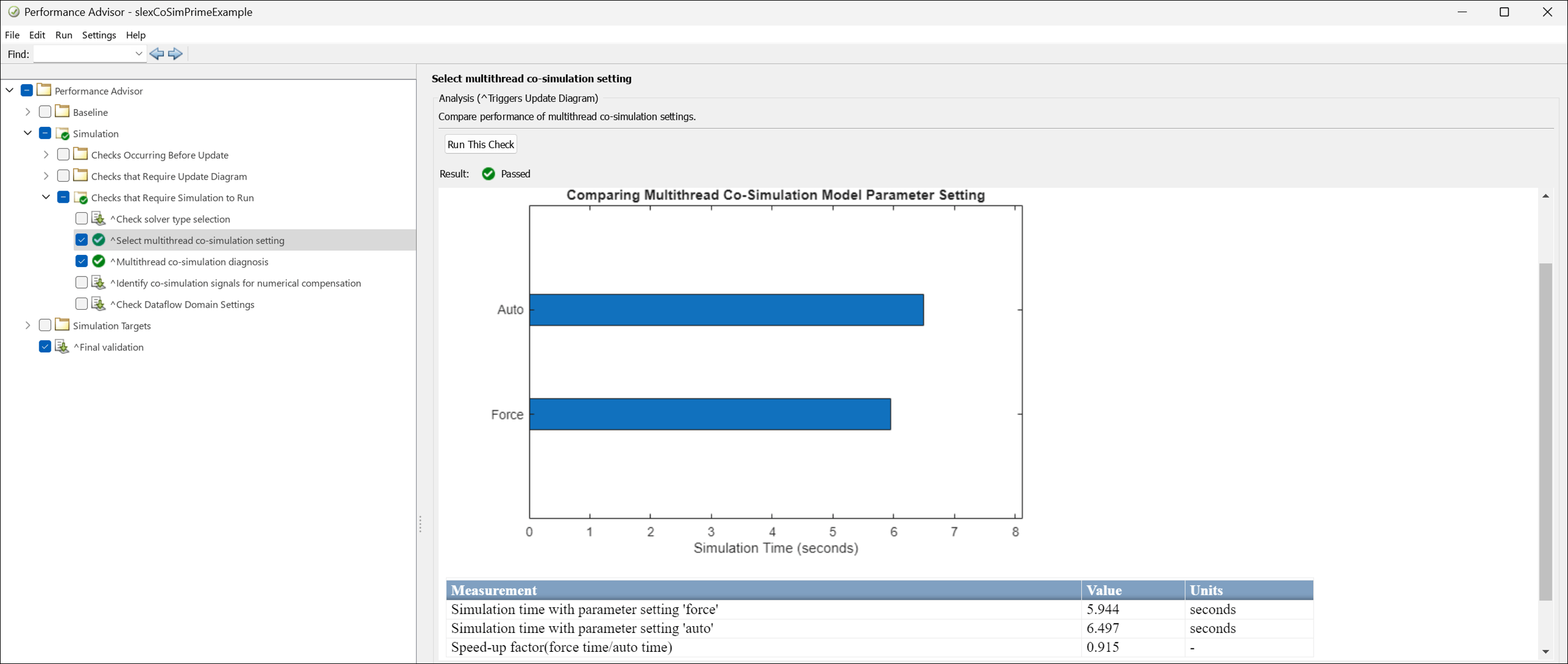
The Performance advisor shows multithreaded simulation comparison between auto and force

Python Importer: Improve simulation performance of Python class methods integrated into Simulink

Python Importer generates blocks that integrate Python class methods into Simulink. Starting in R2025a, the simulation performance of the blocks generated by Python® Importer is improved through the use of C-wrappers to call the specified Python class methods. Doing so:

  • Enhances the simulation performance of the blocks.

  • Enables simulation in rapid accelerator mode.

  • Supports simulation in model reference with accelerator mode.

To enable this feature, on the block dialog of the generated block, set the Simulate Using: parameter as Code generation.
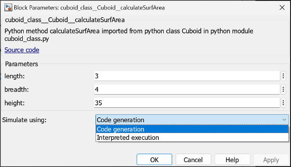
Python block dialog with simulation mode selected as code generation

Use delay blocks with multithreaded co-simulation

Starting in R2025a, you can use the Unit Delay and Delay blocks with thread-safe Simulink components to enable multithreaded co-simulation. Use these blocks to break the dependency of thread-safe blocks on non-thread-safe upstream blocks.

Prior to R2025a, a thread-safe block that depended on a non-thread-safe block could not be multithreaded.

Run simulations from initial operating points while modifying models between simulations

By enabling flexible operating point initialization, you can simulate a model from an initial operating point after making structural changes to the model between simulations. To enable flexible operating point initialization, set the new Operating point contents checksum mismatch model configuration parameter to warning or none.

To identify structural changes in a model, the software compares the contents checksum of the model to the contents checksum in the Simulink.op.ModelOperatingPoint specified as the initial state of the simulation.

  • When you enable flexible operating point initialization, if the contents checksum of the model does not match the contents checksum of the initial operating point, the software initializes the simulation using as much information as possible from the operating point.

  • When flexible operating point initialization is disabled, as in prior releases, if the contents checksum of the model does not match the contents checksum of the initial operating point, the software issues an error.

By default, flexible operating point initialization is disabled because simulation results can differ significantly between simulations initialized using only a portion of the operating point information and simulations that run from the start without an initial operating point. For more information, see Speed Up Simulation Workflows by Using Model Operating Points.

To understand how the simulation is initialized using the data in the specified operating point, you can:

  • Inspect the Simulink.SimulationMetadata object returned with the simulation results. The ModelInfo property includes a structure named OperatingPointMismatches that provides information about specific differences between the model and the operating point, including details about unused operating point data and paths of uninitialized blocks in the model.

  • Configure the software to issue warnings that provide information about specific differences between the model and the initial operating point by setting the Operating point contents checksum mismatch parameter to warning.

Log model operating points to MAT file during simulation

You can now log model operating points during normal, accelerator, and rapid accelerator simulations. To ensure that the logged operating point data is saved if the simulation issues an error or MATLAB crashes during simulation, the operating points are logged to a MAT file. By logging operating points, you can:

  • Recover from crashes faster by resuming the simulation from an operating point logged before the crash.

  • Debug errors that occur in long-running simulations faster by starting a simulation debugging session from an operating point logged before the error occurred.

  • Run a single simulation to save the model operating point at each transition point in simulations that have predetermined and structured phases. You can then save time by using the appropriate operating point in subsequent simulations so that each simulation runs only the relevant phases.

Before R2025a, you could save the operating point of a model only at the end of simulation or on demand by calling the get_param function while paused in simulation. If the simulation issued an error or MATLAB crashed during simulation, no operating point data was saved. For more information, see Speed Up Simulation Workflows by Using Model Operating Points.

Improved performance for solving algebraic loops that have multiple algebraic variables

Models with algebraic loops that have multiple algebraic variables show improved performance in the execution phase of simulation. The improvement in simulation execution time is directly proportional to the number of algebraic variables involved in a given algebraic loop.

To evaluate the performance improvement for a model, run an equivalent simulation of the model in R2024b and R2025a and compare the execution time captured in the simulation metadata. For example, consider the model sldemo_hydcyl4, which has an algebraic loop that involves five algebraic variables. To check the number of algebraic loops and the number of algebraic variables in each loop, open the model and use the Simulink.BlockDiagram.getAlgebraicLoops function.

mdl = "sldemo_hydcyl4";
openExample("simulink_general/sldemo_hydcyl4Example",SupportingFile=mdl)
Simulink.BlockDiagram.getAlgebraicLoops(mdl)
 AlgebraicLoop with properties:

                   Model: [1×1 Simulink.BlockDiagram]
                      Id: [0 1]
    VariableBlockHandles: [5×1 double]
            BlockHandles: [28×1 double]
            IsArtificial: 0

To evaluate the performance improvement for the model, run this code in R2024b and R2025a.

set_param(mdl,MaxStep="1e-4");
nRuns = 10;
for k = 1:nRuns
    out = sim(mdl);
    t(k) = out.SimulationMetadata.TimingInfo.ExecutionElapsedWallTime;
end
exectime = min(t);

The code:

  1. Sets the maximum step size for the variable-step solver to 1e-4.

    The small maximum step size makes the performance improvement more apparent for the simple model.

  2. Simulates the model ten times in a loop.

  3. Populates an array with the execution time of each simulation.

  4. Takes the minimum simulation execution time to compare between releases.

The simulation runs about 19% faster in R2025a, with these approximate simulation times:

  • R2024b: 0.21 s

  • R2025a: 0.17 s

This evaluation was performed on a Windows 11, AMD EPYC 74F3 @ 3.19 GHz test system.

Set breakpoints on outputs of root-level input ports while stepping block by block

You can now add breakpoints to outputs of root-level input ports while debugging a simulation block by block. When you add a breakpoint to the output of a root-level input port, the simulation pauses when the output value of the port satisfies the breakpoint condition. Set breakpoints on the outputs of root-level input ports when you want to investigate or debug model behavior in response to specific input values.

Root-level input ports include input ports created using Inport and In Bus Element blocks at the root level of either a top model or a referenced model.

  • You can set breakpoints on the outputs of both unique and duplicate root-level input ports.

  • You can set breakpoints on input ports of subsystems, but the breakpoints do not pause the simulation and appear as invalid in the block diagram.

  • Breakpoints on buses are not supported. Setting breakpoints on an input port created using an In Bus Element block is supported only when the port loads a leaf signal with scalar values.

    For more information about signal breakpoint limitations, see Breakpoints List.

  • Breakpoints on the outputs of root-level input ports of referenced models inside variant subsystems are supported only for the active variant choice.

In previous releases, you could add breakpoints on the outputs of root-level input ports, but the breakpoints did not pause the simulation and appeared as invalid in the block diagram. To pause the simulation based on the signal value, you had to add a breakpoint on the block that produces the signal the port receives.

Enable Stateflow and MATLAB Function block debugging from the Breakpoints List

Using the new Debug Stateflow charts and MATLAB Function blocks option, you can enable the Allow setting breakpoints during simulation model configuration parameter from the Breakpoints List. With the Allow setting breakpoints during simulation parameter enabled, you can:

  • Add breakpoints in Stateflow charts, State Transition Table blocks, Truth Table blocks, and MATLAB Function blocks during simulation.

  • Step into and out of Stateflow charts, State Transition Table blocks, and MATLAB Function blocks while stepping block by block through simulation.
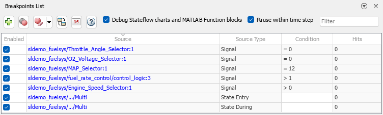
The Breakpoints List shows several signal breakpoints and Stateflow breakpoints in the model named sldemo_fuelsys. Both the Debug Stateflow charts and MATLAB Function blocks and the Pause within time step options are selected.

Trace and highlight signals through bus element ports and model reference variants

You can now trace and highlight signals through bus element ports and through the active variant choice in model reference variants.

For more information about signal tracing and highlighting, see Highlight Signal Sources and Destinations and sltrace.

SIMD Simulation Targets: Support hardware acceleration on Apple silicon Macs

You can now leverage single instruction, multiple data (SIMD) instructions to accelerate simulations on Apple silicon Macs.

For more information, see Hardware acceleration.

Log data directly to an MLDATX file

Log data directly to an MLDATX file instead of the workspace using model settings. To log data to an MLDATX file, in the Configuration Parameters dialog box, in the Data Import/Export pane, specify a filename with an .mldatx extension in the Log data to file text box. Logging data to an MLDATX file typically results in a smaller file size. The MLDATX file created when you select Log data to file is similar to a Simulation Data Inspector session file but contains only the data for a single run without view or comparison information.
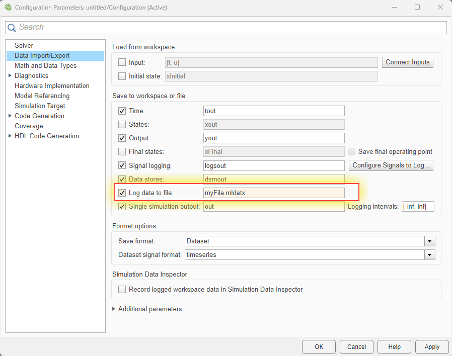
The Configuration Parameters dialog box with the Log data to file option highlighted

Query MLDATX file descriptions and types

MLDATX files can store many different types of data, including Simulation Data Inspector sessions, Signal Analyzer sessions, and Simulink test results. You can now query MLDATX file types and descriptions.

  • To determine the type of MLDATX file, use the matlabshared.mldatx.getType function.

    matlabshared.mldatx.getType("myFile.mldatx")
    ans =
    
        'Simulation Data Inspector File'
  • To get a description of the data contained in an MLDATX file, use the matlabshared.mldatx.getDescription function.

    matlabshared.mldatx.getDescription("myFile.mldatx")
    ans =
    
        'Contains Simulation Data Inspector data.'

Configure Simulation Data Inspector comparisons to ignore signal unit mismatches

Before R2025a, the Simulation Data Inspector always compared signals units when comparing signals. Now, you can specify the name-value argument "Units=Ignore" in the Simulink.sdi.compareRuns and Simulink.sdi.compareSignals functions to ignore signal unit mismatches. When you do not specify the Units name-value argument as"Ignore", the Simulation Data Inspector compares signal units only when both the baseline and comparison signals have units.

Choose whether to export data to the workspace when clearing the Simulation Data Inspector

Before R2025a, the Simulink.sdi.clear function always exported data from the Simulation Data Inspector repository to the workspace before deleting runs. Now, to reduce the time needed to clear the Simulation Data Inspector repository, you can choose not to export data to the workspace before deleting.

Simulink.sdi.clear(Export=false)

Stream fixed-point data to a MATLAB callback function during simulation

Use the data access functionality in the Instrumentation Properties dialog box of a logged signal with fixed-point data to stream that data to a MATLAB callback function during simulation.

Post-process parsim and batchsim simulation results

Starting in R2025a, you have multiple options to post-process parsim and batchsim simulation results.

You can specify a location path for the simulation results while running parsim and batch simulations with the simulink.multisim.DesignStudy object. You can use the OutputLocation name-value pair with the parsim and batchsim functions when using the simulink.multisim.DesignStudy object for your simulation inputs.

To allow parallel post-processing of the simulation results, you can now use a custom MATLAB datastore, MultisimDatastore. MultisimDatastore can iterate over and post-process multiple completed simulations.

 Functionality being removed or changed

Support for ModelDataLogs format has been removed

Errors

Data stored in the ModelDataLogs format, including data stored in Simulink.ModelDataLogs, Simulink.Timeseries, Simulink.TSArray, and Simulink.SubsysDataLogs objects, is no longer supported. Use another supported format, such as Dataset, instead.

Live streaming no longer supported in XY visualizations

Behavior change

To avoid scalability issues, data is no longer streamed to XY visualizations in the Simulation Data Inspector, Record block, or XY Graph block.

Component-Based Modeling

 Simulate referenced models using variable-step local solvers

You can now configure a referenced model to use a variable-step local solver. Since the local solver feature shipped in R2022a, only fixed-step local solvers were supported. When you use a variable-step local solver, the Communication step size parameter of the Model block specifies when the parent and local solvers exchange data. Within the interval between hit times for the communication step size, the variable-step local solver determines the size of each local step based on the dynamics of the continuous states in the referenced model and the tolerance values you specify for the local solver.

When you use a variable-step local solver, only Zero-order hold input and output signal handling are supported. Variable-step local solvers do not support:

For more information about local solvers, see Use Local Solvers in Referenced Models. For an example of using a local solver, see Improve Simulation Performance by Using Local Solvers.

 Python Code Block: Bring Python code into Simulink

Starting in R2025a, you can use the Python Code block to integrate your existing Python code into Simulink. This block enables you to import or write native Python code directly within the block dialog box. You can use the block dialog box to define block input ports, output ports, parameters, and persistent variables that interface with the Python code. For an example of using Python code, see Integrate Low Pass Filter Python Code into Simulink Using Python Code Block.

To integrate Python code using the Python Code block, in the block dialog box:

  • In the Ports and Parameters table, define input ports, output ports, parameters, and persistent variables.

  • On the Initialize tab, perform one-time setup tasks like importing class from module and initializing the class.

  • On the Output tab, specify the code for defining the outputs of the block at every time step.

  • On the Terminate tab, specify tasks for the block to perform before the end of simulation.
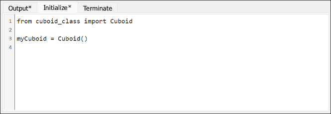
    Python block initialize pane

    Python block output pane

Zero-crossing detection, instance parameter, operating point, and fast restart support for fixed-step and variable-step local solvers

Both fixed-step and variable-step local solvers now support:

  • Zero-crossing detection

  • Instance parameters in all simulation modes

  • Saving final operating points and loading initial operating points in normal mode simulations

  • Fast restart for normal mode simulations

Since the local solver feature shipped in R2022a, local solvers have not supported zero-crossing detection, saving and loading operating points, or fast restart. Model arguments were supported only in normal mode simulations. For more information, see Use Local Solvers in Referenced Models.

Simulink Units: Physical quantity-only specifications now supported

Simulink now supports physical quantity-only unit specifications. This support enables blocks to accept any kind of unit for the Unit parameter specification using the format inherit@physical quantity, @physical quantity, or an expression of units, also known as derived units. For more information, see Physical Quantity-Only Specifications.

Connect In Bus Element and Out Bus Element blocks to components by port name

When you connect multiple In Bus Element or Out Bus Element blocks to a Subsystem or Model block at once, the software now connects the ports based on port name matches before other criteria.

To connect multiple In Bus Element or Out Bus Element blocks to a Subsystem or Model block at once:

  1. Select the In Bus Element or Out Bus Element blocks.

  2. Press Ctrl and click the Subsystem or Model block.
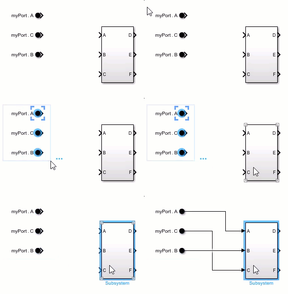
The video shows three In Bus Element blocks labeled myPort.A, myPort.C, and myPort.B simultaneously connecting to the same Subsystem block, which has input ports named A, B, and C. The block labeled myPort.A connects to port A, the block labeled myPort.C connects to port C, and the block labeled myPort.B connects to port B.

The software continues to connect Subsystem and Model blocks based on port name matches before other criteria.

For more information, see Connect Blocks.

Simplify component interfaces with bus element ports programmatically

To simplify subsystem and model interfaces with bus element ports, you can now use these functions:

  • simplifyInterfacesWithBusPorts — Update a model or subsystem file to use bus element ports for buses at the model and subsystem interfaces.

  • createBusPort — Create a bus element port from a Bus Creator or Bus Selector block connected to a port block.

For more information, see simplifyInterfacesWithBusPorts and createBusPort.

Faster rebuild checks for model hierarchies with changes in referenced models

When you modify a referenced model without changing its interface or making changes to its parent models, the model reference rebuild checks are now faster. This performance improvement applies when the referenced model and its parent models simulate in accelerator mode and the Rebuild configuration parameter of the top model in the model hierarchy is set to If changes in known dependencies detected. In this scenario, the rebuild checks no longer check for structural changes in the parent models.

For example, open and simulate a model hierarchy. The simulation generates model reference simulation targets for the referenced models that simulate in accelerator mode.

openExample("aeroblks_hl20/HL20ProjectWithOptionalFlightGearInterfaceExample")
openProject("asbhl20");
simIn = Simulink.SimulationInput("asbhl20");
simIn = setModelParameter(simIn, SimulationMode="accelerator");
simOut = sim(simIn);

Modify a referenced model in a way that does not affect its interface. For example, change how to process the inputs of a Sum block.

load_system("asbhl20_FCSApp")
set_param("asbhl20_FCSApp/Sum3", Inputs="+-|")
save_system("asbhl20_FCSApp")

In this example, when you simulate the model hierarchy again, the parent model simulation target code recompiles about 4x faster than in the previous release.

simOut = sim(simIn);

The build summaries indicate that the approximate code recompilation times are:

  • R2024b: 13.7 s

  • R2025a: 3.57 s

This evaluation was performed on a Windows 11, AMD EPYC 74F3 @ 3.19 GHz test system.

For information on how to identify interface changes and structural changes, see Determine Why Simulink Accelerator Is Regenerating Code.

Choose diagnostic action to take when find_mdlrefs function finds invalid referenced model names

To control whether the find_mdlrefs function provides an error, warning, or no diagnostic for invalid model names, set InvalidModelNames to "error", "warning", or "ignore".

For more information, see find_mdlrefs.

find_mdlrefs function lets you specify filename with extension

When you specify a filename for the first argument of the find_mdlrefs function, you can now specify the filename with or without the extension. Previously, you could not specify a filename with an extension.

For more information, see find_mdlrefs.

Search under model blocks in model hierarchy using the Simulink.findBlocks and find_system functions

When you use the Simulink.findBlocks and find_system functions, you can now set the LookUnderModelBlocks option to enable search under blocks in a model hierarchy. For example, find_system("mymodel",LookUnderModelBlocks=on,BlockType="Constant") searches for Constant blocks under all blocks in the top-level model mymodel and its referenced models.

Simulink cache file information is more complete

Simulink cache file information now includes the compiler used to generate each build artifact, when applicable and available. To get the compiler information for a build artifact, open the Simulink cache report or use the slxcinfo function.

When you build a model hierarchy, the build log now helps you diagnose why the build did not unpack a Simulink cache file. For example, the build log now lets you know when the software is unable to find a Simulink cache file for a referenced model.

For more information about Simulink cache files, see Share Simulink Cache Files for Faster Simulation.

Pre-configured color palettes in Sample Time Legend

Starting in R2025a, Simulink provides two pre-configured sample time color palettes.

  • The color blind accessible palette provides a color palette that is more accessible.

    simulink.sampletimecolors.applyPalette('color blind accessible(built in)')

  • The classic color palette provides more colors for different sample times than the default color palette. The classic palette contains come of the legacy sample time colors from prior to R2023b release.

    simulink.sampletimecolors.applyPalette('classic(built in)')

Define variant control variables for Initialize Function, Reset Function, Reinitialize Function, and Terminate Function blocks in mask and model workspaces

Previously, variant control variables for Initialize Function, Reset Function, Reinitialize Function, and Terminate Function blocks could originate from the base workspace or a data dictionary. Attempts to use variant control variables from the mask or model workspaces resulted in errors. Starting in R2025a, you can define variant control variables for these blocks in the mask or model workspaces when the Generate preprocessor conditionals parameter is set to off. Using mask and model workspace variables as variant control variables limits the scope of the variables. Limiting the scope helps avoid name conflicts and establishes clear ownership of the variable between the blocks.

Consider a model Vehicle that compares the fuel efficiency of petrol and diesel engine configurations for cars and trucks under various driving conditions. The model includes model reference blocks Truck_Configuration and Car_Configuration, which reference the Truck and Car models, respectively. Within the Truck_Configuration block, there are two Initialize Function blocks for petrol and diesel engines to adjust parameters such as fuel consumption, throttle, and bias for each engine type. Similarly, the Car_Configuration includes the engine settings for cars. Each model uses a variant control variable, cfg, defined in their respective model workspaces. In the Truck model, cfg is set to 1, activating the petrol configuration, while in the Car model, cfg is set to 2, activating the diesel configuration. Previously, you could define cfg in the base workspace or in a data dictionary only, which prevented the use of different values for cfg in separate models. In this example, with the model workspace, cfg is scoped individually within each model, allowing for different values in the car and truck configurations.

When using mask and model workspace variables as variant control variables in the variant blocks, the generated code contains only the active choice. This occurs because support for these workspaces is available only when the Generate preprocessor conditionals parameter is set to off, which corresponds to setting the update diagram variant activation time.

For information on how to limit the scope of variant control variables using mask and model workspaces in variant blocks, see Approaches to Control Active Variant Choice of a Variant Block Using Mask or Model Workspace.

Define variant control variables in reusable subsystems in mask workspaces

In previous releases, variant control variables for a variant block with the Variant activation time parameter set to startup, located within a reusable subsystem, could only originate from the base workspace, model workspace, or a data dictionary. Attempts to use variables from the mask workspace of the reusable subsystem resulted in errors.

Starting in R2025a, these variables can now originate from the mask workspace of a reusable subsystem. This enhancement enables you to encapsulate and manage variant control variables effectively within the subsystem.

For information on how to define variant control variables in the mask workspace, see Control Structural Variations Using Mask Parameters and Model Arguments.

Access compiled properties of inactive blocks

Starting in R2025a, you can access the compiled properties of inactive blocks that are connected to variant blocks with the Variant activation time parameter set to update diagram analyze all choices or code compile. In previous releases, setting the Variant activation time parameter to update diagram analyze all choices or code compile resulted in empty compiled properties for inactive blocks.

This table lists the compiled properties returned for different activation times:

Variant activation timeCompiled properties for model
update diagramCompiled properties only for active choices are available.
update diagram analyze all choicesCompiled properties for active and inactive choices are available.
code compileCompiled properties for active and inactive choices are available.
startupCompiled properties for active and inactive choices are available.
runtimeCompiled properties for active and inactive choices are available.

Consider the Variant Sink block in the slexVariantSourceAndSink model that has the Variant activation time parameter set to code compile. The variant control variable W controls the variant choices in this block. The first variant choice activates when the variant control expression W == 1 evaluates to true, and the second variant choice activates when the variant control expression W == 2 evaluates to true. To compile the model with the first variant choice active and the second variant choice inactive, set the value of W to 1, and then initiate the compilation phase using this command in the MATLAB Command Window. For more information on how to run specific phases of the model, see Use Model Name as Programmatic Interface.

slexVariantSourceAndSink([],[],[],"compile");

The first variant choice becomes active and the second variant choice becomes inactive.
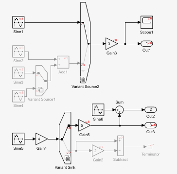
Model in compilation phase with a Variant Sink block connected to an inactive Gain block

You can then retrieve the compiled information of inactive blocks for properties listed in Programmatically Specify Block Parameters and Properties.

For example, to retrieve the structure of port widths of the Gain2 block, which is inactive, use this command.

get_param(gcb,"CompiledPortWidths");

Of all the properties, CompiledPortDesignMin and CompiledPortDesignMax require blocks to be active to determine the minimum and maximum values that a block's ports can accommodate during simulation. These properties return empty values for inactive blocks.

Input to output mapping in Variant Subsystem blocks with no active variant choices

Starting in R2025a, the Variant Subsystem block includes a new Built-in passthrough choice parameter and a renamed Built-in empty choice parameter in the Block Parameter dialog box for handling scenarios when none of its variant choices are active. These updates also apply to the Convert Subsystem to Variant Subsystem dialog box.

  • Built-in passthrough choice — When you select the new Built-in passthrough choice parameter, Simulink adds a nonmodifiable variant choice entry to the Variant choices table with its variant control set to (default). This entry enables the input port values to be assigned to the output ports when no variant choice is active. This entry does not appear as a visible variant choice in the Variant Subsystem block. This functionality applies to Variant Subsystems that:

    • Have only data ports, with no other types of input and output ports

    • Have an equal number of data input and output ports for variant choices

    • Have input and output ports that exactly match the ports of variant choices

    Programmatically, use the PassThrough parameter to assign the input port value to the output port when no variant choice is active.

    set_param(gcb,PassThrough="on")

    The generated code remains consistent with the Allow zero active variant controls parameter from previous releases, except that it now assigns input port values to the output port in the else condition.

  • Built-in empty choice — The Allow zero active variant controls parameter is now renamed to Built-in empty choice. When you select this parameter, Simulink adds a nonmodifiable variant choice entry to the Variant choices table with its variant control set to (default). This entry enables the output port to continue grounding to zero when no variant choice is active, as in previous releases. This entry does not appear as a visible variant choice in the Variant Subsystem block

    Programmatically, you can use the AllowZeroVariantControls parameter to ground the output when no variant choices are active. However, AllowZeroVariantControls will be removed in a future release. Instead, use the EmptyChoice parameter:

    set_param(gcb,EmptyChoice="on")

    The generated code remains consistent with the Allow zero active variant controls parameter from previous releases, where zero is assigned to the output port in the else condition.

Block Parameters dialog box of a Variant Subsystem block displaying the new Built-in passthrough choice and the renamed Built-in empty choice parameters. The selected Built-in passthrough choice parameter creates a default variant choice in the Variant choices table

If you export a model containing a Variant Subsystem block with either the Built-in empty choice or Built-in passthrough choice parameter selected to an earlier release, the Variant Subsystem in the exported model has the Allow zero active variant control parameter selected.

For more information, see Manage Variant Components to Pass Specified Values from Inactive Variant Subsystems with No Active Choice (Simulink Coder).

Resolve memory contentions in Variant Subsystems with automatic signal conversion

Previously, when the Outport blocks of a Variant Subsystem block received signals from a single source, errors due to memory contention could occur. The error included a Fix button, prompting you to insert a Signal Conversion block at the source of the Outport blocks to resolve the incompatibility issue.

Starting in R2025a, Simulink inserts the Signal Conversion block at the source of the Outport blocks to temporarily store signal data in memory, allowing signals to be processed sequentially, thus eliminating the need for manual fixes.

Reduce overhead and irrelevant diagnostic messages by suppressing callbacks for inactive variant choices and commented blocks

Previously, Simulink executed block callbacks whenever the modeling action associated with the callback occurred, regardless of whether the block was active or uncommented. Starting in R2025a, Simulink suppresses block callbacks for inactive variant choices of Variant Subsystem blocks with the update diagram activation time and for commented blocks during operations such as loading, compiling, simulating, saving, and closing the model. This enhancement reduces computational overhead and prevents unnecessary diagnostic messages from blocks that do not impact the current iteration of the model.

This change applies to the block callbacks, including the LoadFcn callback, as listed in the table below. For example, Simulink does not execute the LoadFcn callback for inactive variant choices, even when you attempt to find the active and inactive variant choices by using the @Simulink.match.allVariants match filter in the find_system function.

While other block callbacks require certain modeling actions to execute, you are not required to perform actions, such as reloading the model, for the LoadFcn to execute in each iteration. Simulink automatically runs the LoadFcn callback of a block whenever it determines that the block is active or is uncommented. Once Simulink executes the LoadFcn in an iteration, it is not triggered again if the block becomes inactive and then active in subsequent iterations, as it is already executed to avoid redundant executions.

This table lists the suppressed block callbacks for inactive variant choices of Variant Subsystem blocks with the update diagram activation time and the commented blocks. For detailed information on these callbacks, see Block Callbacks.

Block Callback ParameterWhen Callback Executes
ContinueFcnBefore the simulation continues
InitFcnBefore the block diagram is compiled and before block parameters are evaluated
LoadFcnAfter the block diagram is loaded
ModelCloseFcnBefore the block diagram is closed
PauseFcnAfter the simulation pauses
PostSaveFcnAfter the block diagram is saved
PreSaveFcnBefore the block diagram is saved
StartFcnAfter the block diagram is compiled and before the simulation starts
StopFcnAt any termination of the simulation

Suppression of block callbacks does not apply in these scenarios:

  • Callbacks for these block-specific operations such as cut, copy, paste, and delete are not suppressed. For detailed information on these callbacks, see Block Callbacks.

    Block Callback ParameterWhen Callback Executes
    ClipboardFcnWhen the block is copied or cut to the system clipboard
    CloseFcnWhen the block is closed using the close_system function
    CopyFcnAfter a block is copied
    MoveFcnWhen the block is moved or resized
    NameChangeFcnAfter a block name or path changes
    OpenFcnWhen the block is opened
    ParentCloseFcnBefore closing a subsystem containing the block
    PreCopyFcnBefore a block is copied
    PreDeleteFcnBefore a block is graphically deleted
    UndoDeleteFcnWhen a block deletion is undone
    DeleteChildFcnAfter a block or line is deleted in a subsystem
    SCDConfigFcnAfter the configuration of the System Composer model changes
    DeleteFcnAfter a block is graphically deleted
    DestroyFcnAfter a block is graphically deleted
  • The callbacks for blocks within models or subsystem files inside a commented or an inactive Model block or Subsystem Reference block are not suppressed.

  • The mask initialization and mask parameter callbacks are not suppressed. For the list of applicable callbacks, see Author Mask Initialization and Callbacks and Mask Parameters.

Detect undefined variant control variables in Variant Source and Variant Sink blocks during edit-time

Starting in R2025a, Variant Source and Variant Sink blocks issue errors for undefined variant control variables during model editing. The blocks indicate errors with a red highlight around the border. To see a description of the issue, pause on the highlighted block. You can then click the error symbol to open the notification dialog box that lists predefined fixes. Select the most appropriate fix to resolve the issue, and click the Fix button. Depending on the chosen solution, you may need to provide additional information to resolve the error. After the fix is applied, the red border disappears, indicating the issue is resolved. If the fix is unsuccessful, a failure message is displayed.

Consider a model that contains a Variant Source block Controller, which has two input ports.
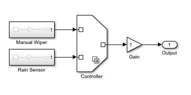
Model containing a Variant Source block, Controller

In the Block Parameters dialog box of the Controller block, specify the variant control expressions enumController.manual == 1 and enumController.sensor == 1. The expressions use the enumeration class enumController and its enumeration values, which are not defined.
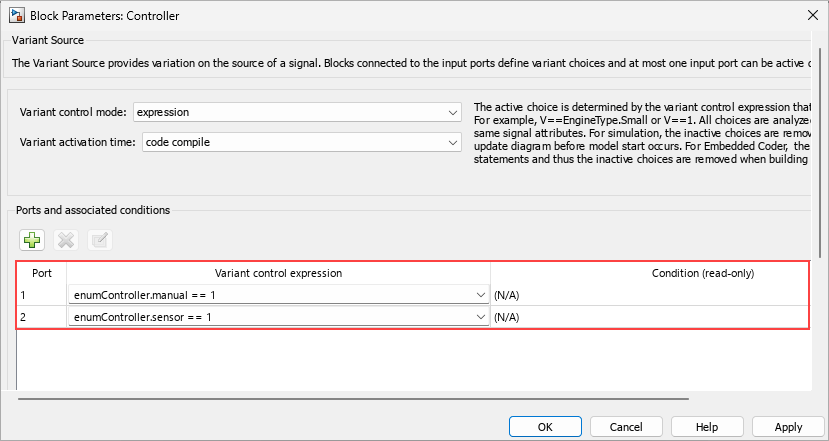
Block Parameters dialog box of the Controller block with variant control expressions enumController.manual == 1 and enumController.sensor == 1

After applying the changes, when you close the Block Parameters dialog box, a red highlight appears on the border of the block indicating that the enumController class is invalid. Pause on the block and then click the error symbol. From the notification dialog box, select the fix that corresponds to Create a new enumeration type.
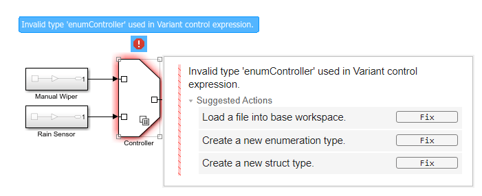
Variant Source block Controller is outlined in red, indicating an error. An error symbol above the block provides a detailed description of the issue. A notification dialog box lists predefined solutions to resolve the error.

In the Create New Enumerated Type dialog box, specify the required details for the enumeration class enumController, and then click Create.
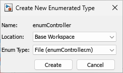
Create New Enumerated Type dialog box displays the enumerated class location set to the base workspace, with the type specified as enumController.m

Navigate through the explorer to specify the location where the model is stored, or choose a location already added to the MATLAB path to create the enumController enumeration class in the file enumController.m. The enumeration class is an integer-based enumeration derived from the built-in data type int32. It includes two enumeration values manual and sensor with underlying integer values 0 and 1, respectively. The values are organized alphabetically.

classdef enumController < Simulink.IntEnumType
    enumeration
        manual(0)
        sensor(1)
    end
    methods (Static)
        function retVal = getDefaultValue()
            retVal = enumController.manual;
        end
    end
end

Make any necessary changes according to your requirements. Once the changes are applied, the red highlight on the border disappears, indicating the issue is resolved.

Simulate and generate code for models with variant parameters in model workspace

Starting in R2025a, simulation and code generation is supported for models that define variant parameters (Simulink.VariantVariable objects) in the model workspace. To simulate or generate code from such models, set the ActivationTime property of the Simulink.VariantControl object used as the variant control variable for the variant parameter to update diagram, update diagram analyze all choices, or startup. The objects associated with the variant parameter object such as the Simulink.VariantControl object, the Simulink.Parameter object used to set the Specification property, and any Simulink.Parameter objects used as values of the variant parameter must be defined in the model workspace along with the parameter.

For more information, see Configure Variant Parameter Values for Instances of Referenced Models and Generate Code for Instance-Specific Variation of Variant Parameter Values in Model Reference Hierarchy (Simulink Coder).

Configure code generation for variant parameters in model workspace using Code Mappings editor

You can use the Code Mappings Editor — C (Embedded Coder) to configure the code generation attributes for ERT-based and GRT-based targets for Simulink.VariantVariable and Simulink.VariantControl objects defined in the model workspace of a model. The objects are listed in the Code Mappings editor if:

  • The Simulink.VariantControl object has its Value property set to a Simulink.Parameter object.

  • The Simulink.VariantVariable has its Specification property set to a Simulink.Parameter object.

If the model is configured to use a data code interface, you can specify a storage class defined in the Embedded Coder Dictionary that is associated with the model. If the model uses service code interfaces defined in a shared Embedded Coder Dictionary, you can map the Simulink.VariantVariable and Simulink.VariantControl objects to parameter tuning and parameter argument tuning service interfaces, which enables you to configure the parameters to be tunable in the generated code.

The Parameters tab of the Code Mappings editor shows the variant parameters and the associated objects, grouped by category. Variant parameter and variant control objects that are defined in the base workspace are in the External Parameter Objects category. For variant parameters, Storage Class is set to read-only because it is derived from the Specification object associated with the parameter.
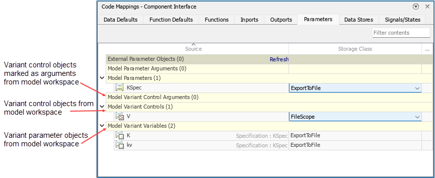
Code mappings editor shows variant parameter and dependent objects

These functions provide programmatic support for Simulink.VariantVariable and Simulink.VariantControl objects in the code mappings programming interface.

FunctionPurpose
setModelVariantControl (Simulink Coder)

Set code mapping properties of Simulink.VariantControl objects

getModelVariantControl (Simulink Coder)

Get code mapping properties of Simulink.VariantControl objects

getModelVariantVariable (Simulink Coder)

Get code mapping properties of Simulink.VariantVariable objects

You can now use these values for the elementCategory argument of the find (Embedded Coder) function, which finds model elements in the code mapping categories.

Argument valuePurposeExample
"ModelVariantControls"Find Simulink.VariantControl objects present in the model code mappings
% Find Simulink.VariantControl objects 
% with ExportedGlobal storage class from code mappings
cm = coder.mapping.api.get(modelname);
find(cm,"ModelVariantControls",StorageClass="ExportedGlobal");
"ModelVariantControlArguments"Find Simulink.VariantControl objects set as model arguments and present in the model code mappings
cm = coder.mapping.api.get(modelname);
find(cm,"ModelVariantControlArguments");
"ModelVariantVariables"Find Simulink.VariantVariable objects present in the model code mappings
cm = coder.mapping.api.get(modelname);
find(cm,"ModelVariantVariables");

For an example, see Configure Code Generation for Variant Parameters in Model Workspace Using Code Mappings Editor (Simulink Coder).

Generate code for variant parameters with code compile activation time defined in a data dictionary linked to a subsystem file

Starting in R2025a, you can generate code for variant parameter (Simulink.VariantVariable) objects with variant activation time set to code compile when they are defined in a data dictionary linked to a subsystem file. Previously, code generation was supported for such variant parameters only for variant activation times other than code compile.

 Specify separate memory sections, header, and definition files for the parameter structure array and pointer used by a variant parameter bank

Before R2025a, when you grouped variant parameters in a model using variant parameter banks (Simulink.VariantBank objects), you could specify only a single memory section to place the structure array that groups the parameter values and the pointer that selects the active set of values from the array. The code generator placed the declarations and definitions of both the array and the pointer in the same header and definition files that you specified.

Starting in R2025a, you can specify separate memory sections, header, and definition files to place the structure array and pointer in the generated code. You can also specify a type qualifier that is applied to the declaration and definition of the array and pointer variables in the code.

To support these enhancements, the Simulink.VariantBank class has two new properties, AllChoicesCoderInfo and ActiveChoiceCoderInfo. The Simulink.VariantBankCoderInfo class has a new property named Qualifier.

For an example on variant parameter banks, see Group Variant Parameter Values and Conditionally Switch Active Value Sets in Generated Code (Embedded Coder).

 Compatibility Considerations

The BankCoderInfo property of the Simulink.VariantBank class will be removed. Use the AllChoicesCoderInfo and ActiveChoiceCoderInfo properties instead. If your existing code sets the BankCoderInfo property, Simulink uses this value to automatically set the value for the AllChoicesCoderInfo and ActiveChoiceCoderInfo properties.
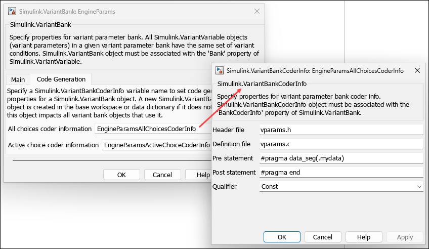
Dialog boxes of variant bank and variant bank coder info

Set value of Simulink.VariantControl object and values of Simulink.VariantVariable choices to mathematical expressions

You can set the value of a Simulink.VariantControl object and the values of a Simulink.VariantVariable object to mathematical expressions and then use Embedded Coder to generate code that preserves these expressions.

  1. Create a Simulink.Parameter object or an object of a class that inherits from Simulink.Parameter.

  2. Set the Value property of the object to the expression by using the slexpr function.

  3. Use the object to set the value of the variant control or the values of the choices of a variant parameter.

For relevant code generation capabilities and considerations, see Code Generation of Parameter Objects With Expression Values (Embedded Coder). For an example, see Use Mathematical Expressions as Values of Simulink.VariantControl Objects and Simulink.VariantVariable Choices.

Use variant parameter banks in model reference hierarchy

You can simulate and generate code for a model reference hierarchy that uses a variant parameter bank (Simulink.VariantBank) to group variant parameters (Simulink.VariantVariable objects) used by models across the hierarchy. Previously, when you used Embedded Coder to generate code that switches parameter banks using a pointer variable, model reference hierarchy was not supported. Starting in R2025a, the code generator identifies all variant parameters in a variant parameter bank within the base workspace or data dictionaries visible to the model hierarchy and includes them in the parameter bank definition. The header file that contains the type definition of the variant parameter bank is generated in a shared utilities folder slprj/target/_sharedutils, where target is the name of the system target file for code generation. This mechanism enables sharing the variant parameter bank across multiple models in the hierarchy. For an example, see Generate Code for Variant Parameter Banks in Model Reference Hierarchy (Embedded Coder).

Use Parameter Writer block to initialize variant control value of variant parameter

You can use Parameter Writer blocks within an Initialize Function block to initialize Simulink.VariantControl objects associated with a variant parameter (Simulink.VariantVariable) with startup activation time. For an example, see Initialize Variant Control Value of Variant Parameter Using Parameter Writer Block.

Variant Manager for Simulink: Support for Subsystem files

You can now launch Variant Manager on a Subsystem block diagram and define variant configurations for the block diagram by using the Variant Manager for Simulink software support package. Variant Manager supports operations such as:

  • Importing variant control variables, defining and activating variant configurations, defining constraints, and finding control variable usage in a configuration

  • Visualizing and interacting with the model hierarchy

  • Composing top-level configurations using referenced component configurations

  • Defining a variant configuration data object for the Subsystem block diagram to save the variant configurations and constraints, and exporting the object to a MAT file or MATLAB script file for reuse

Variant Manager does not support these functionalities with Subsystem block diagrams from the user interface or from the MATLAB Command Window.

  • Generating variant configurations automatically

  • Obtaining compile-time information using Update Model

  • Using Variant Reducer and Variant Analyzer

Variant Manager for Simulink: Support for variant parameters, and Variant Start and Variant End blocks when generating variant configurations

When you generate variant configurations automatically by using Variant Manager or the Simulink.VariantManager.generateConfigurations function, the process also supports these modeling elements:

  • Variant parameters (Simulink.VariantVariable objects) that are defined in the base workspace or data dictionaries linked to the model

  • Variant Start and Variant End blocks

The auto-generation process identifies variant control variables used by these modeling elements and includes their possible combinations when generating variant configurations for the model.

Variant Manager for Simulink: View variant configuration definition in Simulink Test Manager results and reports

When using a variant configuration to run a test case or test iterations in Simulink Test Manager, you can view the definition of the applied variant configuration in the test case results and test iteration results. This enhances traceability from test results to the variant configuration definition used during testing.

To view this definition in the Simulink Test Manager user interface, double-click the test case or iteration result in the Results and Artifacts pane and check the Variant Configuration Details section in the results tab. Alternatively, access the VariantConfiguration property in the sltest.testmanager.TestCaseResult (Simulink Test) and sltest.testmanager.TestIterationResult (Simulink Test) classes to view this data. Additionally, the test results report generated with the sltest.testmanager.report (Simulink Test) method includes the variant configuration definition. For an example, see Run Tests for Variant Models Using Variant Configurations.
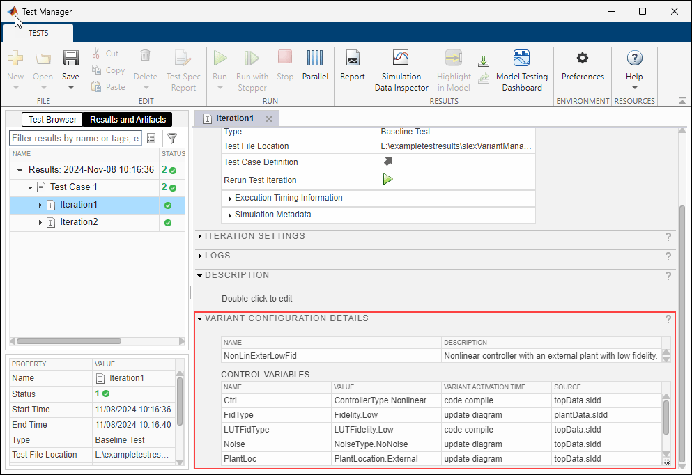
Simulink Test Manager window showing the iteration results with variant configuration details

Variant Manager for Simulink: Define constraints by using referenced component configurations

Starting in R2025a, you can use Variant Manager to define constraints for variant configurations of a top-level model by using predefined variant configurations of referenced components in the model hierarchy. In this way, you can define constraints as condition expressions that include names of referenced component configurations. You can also combine configuration names with variant control variables in the condition expression. Previously, you could specify condition expressions using only the variant control variables used by the model hierarchy.

The function isConfigActive checks if a specified variant configuration is the active configuration for a model. Use this function to specify a component configuration name when defining the constraint, either from the Variant Manager user interface or by using the addConstraint function.

For steps to define a constraint using component configurations from Variant Manager, see Set Up Constraints by Using Component Configurations View.

To verify if a constraint is satisfied by a model and the referenced components in its hierarchy, use the function Simulink.VariantManager.validateConstraint.

Variant Manager for Simulink: Create variant banks to group variant parameters from Variant Manager

Variant Manager now supports creating variant banks to group variant parameters from the Bank view in the Variant Parameters tab. You can either create a new variant bank for the parameters or add them to an existing variant bank. To associate a parameter or a group of parameters with a variant bank, in the Variant Parameters without a variant bank section, on the header row of the required group, click the Create Simulink.VariantBank button . Alternatively, right-click the row and select Create Simulink.VariantBank from the context menu. For more information, see Create Variant Banks for Variant Parameters from Variant Manager.

Variant Manager for Simulink: Support for Variant Assembly Subsystem reduction

Variant Reducer now supports reduction of models that contain Variant Assembly Subsystem blocks. For a Variant Assembly Subsystem block in expression mode that uses an enumeration to add variant choices, Variant Reducer generates reduced enumeration definitions that retain only the members corresponding to the retained variant configurations. Depending on the definition in the parent model, the reduced enumeration is defined either in a class file, in a reduced data dictionary, or in the PostLoadFcn callback of the reduced model using the function Simulink.defineIntEnumType for in-memory enumerations in the MATLAB workspace.

Hide implementation details of custom library blocks to prevent accidental changes

To prevent any accidental changes to your custom library blocks, you can now disable the option to view their implementation details.

To hide the implementation details, select the Subsystem block in the custom library, and then in the Subsystem Block tab in the Simulink Toolstrip, click 'Look Inside' is Allowed in the Look Inside section. This disables the option to view the implementation details of the Subsystem block, both through the user interface and programmatically by using open_system(blk,"force"), where blk is the full name or path of the block in the open or loaded model. These changes apply only to the selected block within the library and not the entire library.

For more information, see Hide Library Block Details in Create Custom Library.

Import types from C++ code into Architectural Data section of Simulink data dictionary

Starting in R2025a, you can use the new DataDictionarySection argument for the Simulink.importExternalCTypes function or DataDictionarySection property of Simulink.CodeImporter.Options class to import types from C++ code into the Architectural Data Editor section of a data dictionary. When importing types that are defined under namespaces, the namespaces are synchronized with the C++ Namespace code generation property of the architectural data type. In previous releases, you could import data types only into Design Data section.
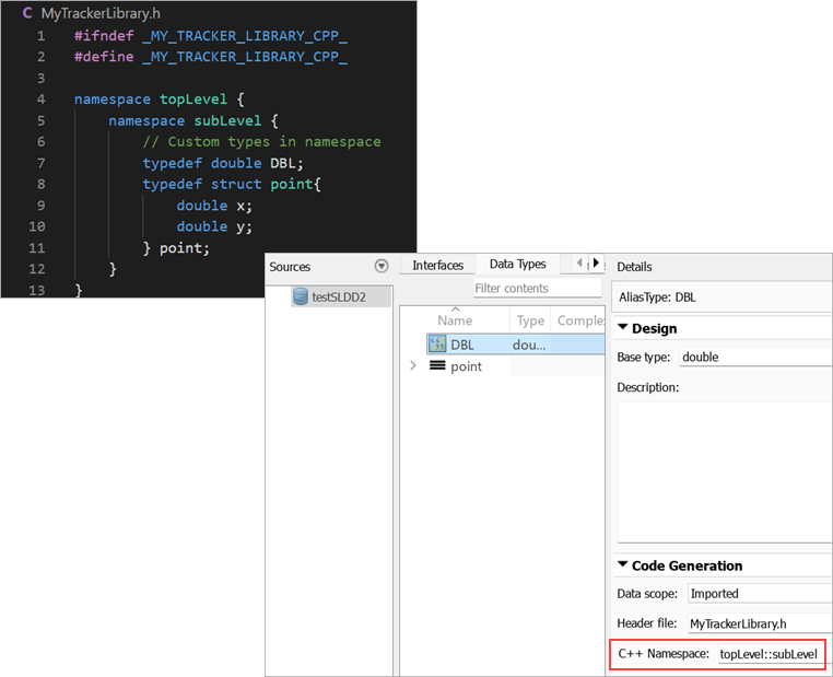
The Architectural Data section of a data dictionary shows imported C++ code namespaces.

New example migrating to a service-oriented architecture

A new example shows how to migrate a signal-based model to a service-oriented architecture. For more information, see Migration to Service-Oriented Architecture Using Model-Based Design.

Use Simulink.VariantControl object to specify active variant of VariantSubsystem block with runtime variant activation time

You can now use a Simulink.VariantControl object to specify variant condition expressions in a Variant Subsystem block with runtime variant activation time. By specifying the ActivationTime property of the object as 'runtime', you can change the active variant of a Variant Subsystem block during simulation or during execution of generated code by modifying the value of the Simulink.VariantControl object through a Parameter Writer block. In addition, when a Variant Subsystem block has Variant activation time set to Inherit from Simulink.VariantControl, the block can now inherit a variant activation time of runtime from its variant control variables of type Simulink.VariantControl.

For more information, see Control Active Choice of Variant Subsystem During Simulation or Execution of Generated Code.

Pass different values for variant control variable to instances of Model block by configuring Simulink.VariantControl object as model argument

When you use a Simulink.VariantControl object as a variant control variable in a Variant Subsystem, Variant Sink, Variant Source, or Variant Start block, you can now configure the variant control variable as a model argument and pass different values for the variable to each instance of a Model block. Similarly, when you use a Simulink.VariantControl object as a variant control variable in a Simulink.VariantVariable object, you can configure the variant control variable as model argument and pass different values to each instance of a Model block to have different values for the Simulink.VariantVariable object in the child model. You can generate code for a Simulink.VariantControl object used as a model argument with variant blocks or with variant parameters.

When you configure a Simulink.VariantControl object as a model argument:

  • The object must be in the model workspace.

  • The value of the object must be a Simulink.Parameter object or a numeric type.

  • ActivationTime property must be set to startup or runtime.

To configure a Simulink.VariantControl object as a model argument, in the Model Explorer, select Argument for the object.

For more information, see Control Active Choice of Variant Subsystem During Simulation or Execution of Generated Code.

Control run-time variant control variables from external code by using the C API

Previously, when you used a Variant Subsystem block with the Variant activation time parameter set to runtime, you modified the variant control variable used to switch the active variant choice by using a Parameter Writer block within the model. In R2025a, you can also modify the control variable from external code by using the C API interface. To enable C API code generation for control variables, select the model configuration parameter Generate C API for: parameters (Simulink Coder).

For more information on run-time variants, see Control Active Choice of Variant Subsystem During Simulation or Execution of Generated Code.

For more information on using the C API interface, see Get Started with C API (Simulink Coder).

 Functionality being removed or changed

Models created from subsystems avoid implicit signal resolution

Behavior change

When you convert a subsystem to a model and the parent model has the Signal resolution configuration parameter set to Explicit and implicit or Explicit and warn implicit, the configuration set of the new model changes Signal resolution to Explicit only. This change avoids implicit signal resolution to Simulink.Signal objects in the new model.

For more information, see Convert Subsystems to Referenced Models and Signal resolution.

Model reference conversion detects unsupported Parameter Writer block configurations

Behavior change

When you convert a subsystem to a model, the conversion now checks for Parameter Writer blocks that write to:

  • A block outside the subsystem

  • A base workspace variable used outside the subsystem

  • A model workspace variable

When a Parameter Writer block writes to one of these destinations, the conversion now detects the issue and fails. In previous releases, the conversion succeeds, but compiling or simulating the new model hierarchy results in an error.

For more information about the conversion process, see Convert Subsystems to Referenced Models.

For more information about Parameter Writer blocks, see Parameter Writer.

find_mdlrefs function honors KeepModelsLoaded value when error occurs

Behavior change

When the software encounters an error while executing the find_mdlrefs function, the KeepModelsLoaded value now determines whether the software closes the models that the function loads. By default, the software closes the models that the function loads.

For more information, see find_mdlrefs.

find_mdlrefs function consistently provides output model names as 1-by-n cell array

Behavior change

The find_mdlrefs function now consistently provides the output model names as a 1-by-n cell array. Previously, when the function returned no model names, the output was a 0-by-1 cell array instead of a 1-by-0 cell array.

New warning for always false default variant choices

Warns

Starting in R2025a, Simulink issue a warning if a variant block has a variant choice set to (default) that is never active during simulation or code generation, helping identify potentially unintended configurations within the model. In previous releases, Simulink did not issue a warning.

Consider a model containing a Variant Source block with three variant choices, where the third choice is set to (default). The variant control variable associated with the block is V. The variant control expressions for the first and the second choices are V ~= 1 and V ~= 2, respectively.

If you set V to 1 and simulate the model, V ~= 2 evaluates to true during simulation, activating the second variant choice. If you set V to 2, the first choice becomes active. However, if V is set to any value other than 1 or 2, both the first and second choices become active, which results in an error since only one choice should be active at a time. In all scenarios, regardless of the value of V, the default variant choice always evaluates to false, making it never active. For such configurations, where the default variant choice is always false, Simulink issues a warning.

For more information, see Default Variant Choice.
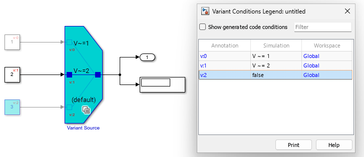
Model containing a Variant Source block with three variant choices, where the third default choice is always false

BankCoderInfo property of Simulink.VariantBank class replaced with AllChoicesCoderInfo and ActiveChoiceCoderInfo

Behavior change

The BankCoderInfo property of the Simulink.VariantBank class will be removed. Use the AllChoicesCoderInfo and ActiveChoiceCoderInfo properties instead to specify code generation attributes for the parameter data array and the pointer variable corresponding to a variant parameter bank. If your existing code sets the BankCoderInfo property, Simulink uses this value to automatically set the value for the AllChoicesCoderInfo and ActiveChoiceCoderInfo properties.

Parameterized library links will be removed

Still runs

Support to modify parameter values in linked library blocks in models will be removed in a future release. To modify the parameter values, you must either disable the library links or change the parameter values in the parent library blocks. For information on disabling library links, see Disable or Break Links to Library Blocks.

Simulink no longer converts value of Simulink.VariantControl objects with startup activation time and integer-convertible double data type to int32

Behavior change

Before R2025a, when you specified the value of a Simulink.VariantControl object with startup variant activation time as an integer-convertible double data type, Simulink implicitly converted the value to int32. In R2025a, this conversion is no longer performed. When you generate code for models that use such variant controls, the code generator declares the variant control variable to be of double data type instead of int32.

Project and File Management

Simulink Comparison and Merge Tools: Updates to the engine and user interface

Starting in R2025a, the Simulink Comparison Tool and Three-Way Merge Tool have new user interfaces that include improvements and new features.

Improvements include:

  • Algorithm updates to improve how the reports display Simulink parameter and structure comparisons

  • Algorithm updates to support more Stateflow elements merging, state transition tables, and Simulink Code mappings comparisons

  • Showing model workspace variable comparison in the two and three-way merge reports

  • Expanded support to display text comparisons for Simulink parameter values, such as LoadFcn and CloseFcn

  • Improved line and segment manual and automatic merges. Segment merges are now handled by their owning lines.

  • Support for find in Simulink three-way merge reports

Simulink Comparison and Merge Tools: Simplify reports using Quick Filters

Starting in R2025a, when you compare or merge files you can simplify the reports using the Quick Filters pane. For more information, see Filter Comparison Report Using Quick Filters.

Comparison and Merge Tools: View tag and branch details for files under source control

Starting in R2025a, when you compare or merge files under source control, the comparison and merge tools include source control information such as the branch name and tags in the files details.
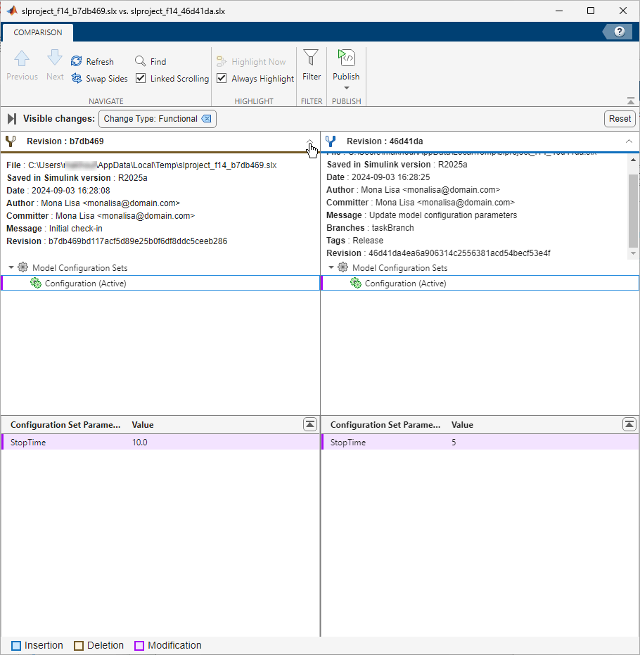
Comparison report shows details for compared files such as tags and branches.

Simulink Comparison: Improved published reports

Starting in R2025a, the printable report you publish from a model comparison is easier to scan and read. Improvements include:

  • Text formatting and highlighting when comparing MATLAB Function blocks and Simulink code parameters, such as LoadFcn callbacks

  • Displaying icons next to node names and screenshots for internal test harnesses and Stateflow subcharts

  • Bigger default font, clearer subsection titles, and page numbering in PDF reports

For more information on how to generate a comparison report, see Export, Print, and Save Model Comparison Results.

Variable Comparison: Compare model workspace variables using new user interface

Starting in R2025a, you can compare variables in the model workspace with improved usability. For more information, see Compare Duplicate Workspace Variables.

Simulink Templates: Pin Simulink template groups

Starting in R2025a, you can pin a group of templates to appear first in the available template groups. If you pin more than one group, Simulink orders them by the most recently pinned.
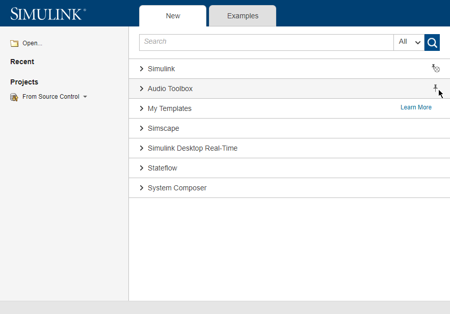
Simulink Start Page shows the list of template groups and Pin and Unpin buttons.

For more information about creating templates, see Create Template from Model and Create Templates for Standard Project Settings.

Upgrade Advisor: Justify or fix failed checks with improved usability

The Upgrade Advisor user interface now includes a simplified toolstrip with these new features.

  • Filter Checks – Filter checks by status, such as Failed, Passed, or Justified.

  • Justify – Justify the violations. Justifications allow you to add a rationale for violations that you observe during the Upgrade Advisor analysis.

  • Fix – Fix the violations automatically when possible.

  • Reports – Export Upgrade Advisor analysis reports in HTML, PDF, and DOCX formats.

For more information, see Upgrade Models Using Upgrade Advisor.

Source Control: Reload Simulink models modified by source control operations

Starting in R2025a, the Simulink Editor automatically reloads models that have been modified by source control actions, such as switching Git branches, performing a Git pull, or executing an SVN update.

You can disable this behavior by adjusting the source control settings. For more information, see Configure Source Control Settings.

Simulink API: Ignore missing project files when exporting projects

You can now ignore missing project files when using Simulink.exportToVersion to export a project to a previous version by setting the AllowMissingFiles argument to true.

Automerge Examples: Set up Simulink automerge in GitLab CI/CD pipeline

This example provides scripts to enable Simulink automerge using GitLab® CD/CD. For more information, see Set Up Simulink Automerge in GitLab CI/CD Pipeline.

Design Evolution Manager: Delete multiple evolution trees

In the Design Evolution Manager app, you can delete two or more evolution trees at the same time. To delete multiple evolution trees, Shift+click to select the evolution tree names in the Tree Browser pane, then click Delete Tree.

Design Evolution Manager: Filter files in comparison view

In the Design Evolution Manager app, when you select two evolutions for comparison, you can filter files in the File Explorer pane using the new Added, Deleted, and Changed buttons.

Data Management

Generate common waveforms with Live Editor

Use the Generate Waveform task to quickly generate signal data from common waveforms. The task also automatically generates code that becomes part of your live script. To add the Generate Waveform task to a live script in the MATLAB Editor, on the Live Editor tab, select Task > Generate Waveform.
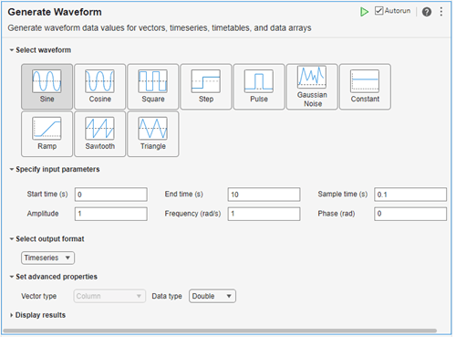
Generate Waveform task in Live Editor

In a code block in the script, type a relevant keyword, such as generate waveform, vector, timeseries, timetable, input, signal, or source. From the completed command completions, select Generate Waveform from the suggested command completions. For more information about Live Editor tasks, see Add Interactive Tasks to a Live Script.

Signal Editor tool updates

The Signal Editor tool has these updates:

  • Replace a signal with a waveform — In the Inputs hierarchy pane, right-click on the signal you want to replace, select Replace the signal with from the context menu, and select one of these waveforms.

    • Constant

    • Step

    • Pulse

    • MATLAB expression, which starts the Author and Replace Signal Data dialog box.

  • Copy and paste signal names, properties, and data

    • To copy all signal information, including name, properties and data, in the Inputs hierarchy pane, right-click on the signal you want to replace and select Copy. Then paste in another area of the Inputs hierarchy pane. In the hierarchy pane, you can paste to the same scenario, a different scenario, or outside a scenario.

    • To copy signal data and time only, in the signal pane, copy the signal and data from the table and paste it into another row and/or column of the signal pane. The size of the pasted data and signal must match the size of the copied signal and data.

    • To replace all signal data with the contents of the clipboard, copy signal data from another source, such as a Microsoft Excel spreadsheet or another Signal Editor signal data table, and then in the signal pane, right-click and select Replace signal data with > Clipboard data. Note:

      • Signal data table and clipboard data table must have the same number of columns.

      • The first column of the clipboard data table must be monotonically increasing.

      • The data type of the existing signal data must be able to cast to the clipboard data.

  • Update a signal in the signal pane. If the signal value is outside the plot area, apply Fit to view to the plot associated with the signal in the signal pane without leaving the signal pane. To apply Fit to view to the associated plot from the signal pane, in the signal pane press Spacebar.

  • The signal data table now accepts hexadecimal (0x) and binary (0b) data formats. To see the data in hexadecimal or binary, the Display Format parameter now lets you set the display format for floating-point and fixed-point data to binary or hexadecimal.

  • To zoom out on the plot, use the Ctrl+- shortcut. Prior to R2025a, the shortcut was Ctrl+PgDn.

For more information, see Work with Basic Signal Data.

createInputDataset allows no compile

The createInputDataset function now enables you to omit the update diagram step when generating dataset objects for root-level Inport or bus element ports in a model. Set the name-value argument UpdateDiagram to false.

Root Inport Mapper user interface updates

The Root Inport Mapper user interface now presents scenario mapping results in separate tabs, enabling you to visually organize these results. Prior to R2025a, all scenario mapping results were presented in one pane.

Tunable enumerated data types in generated code

Starting in R2025a, when you import an enumerated data type definition that is defined in a header file that is external to the MATLAB environment, you can control whether the enumeration values are tunable in generated code. Tunable enumerated values enable you to share data type definitions, for example, that are provided in a master data dictionary, between applications. As required, you can change, add, and reorder the enumerated values in generated code to align with requirements of each application.

For more information, see Configure Enumerated DataTypes for Tunability in Generated Code, Use Enumerated Data in Simulink Models, Simulink.defineIntEnumType, and Simulink.importExternalCTypes.

Parameter Quantization Advisor: Simplified application of settings and app data refresh

The Parameter Quantization Advisor app has simplified application of toolstrip settings and refresh of data in the app. When you adjust settings in the app, the Parameter Quantization Advisor applies the Detect precision loss settings to the model. Data in the app is refreshed when the app is relaunched, when you update the model, or when you click the Refresh Data button.

Open Parameter Quantization Advisor app from Simulink model

In addition to opening the Parameter Quantization Advisor app from the Diagnostic Viewer, there are two new ways to open the app from a Simulink model:

  • Open the app from the Simulink toolstrip. On the Debug tab, under Diagnostics, click Parameter Quantization Advisor.

  • Use the model name to open the Parameter Quantization Advisor app from the MATLAB Command Window:

    parameterQuantizationAdvisor("model_name")

Simulate models that use enumerations in MATLAB namespaces

Starting in R2025a, you can simulate Simulink models that use an enumerated type that is derived from Simulink.IntEnumType and is defined inside a MATLAB namespace. When generating C code for simulation targets, Simulink prefixes the enumerations with the MATLAB namespace. When generating C++ code for simulation targets, Simulink generates the enumerations in a namespace.

For more information, see Use Enumerated Data in Simulink Models.

Simulink.io.SignalBuilderSpreadsheet now supports csv files with headers

The Simulink.io.SignalBuilderSpreadsheet class now supports csv files with headers.

Log data to file with simulation object

Starting in R2025a, you can log data to file when using the simulation object. Use the setModelParameter function on the simulation object to set the LoggingToFile to 'on'.

sm = simulation('model')
sm = setModelParameter(sm,LoggingToFile='on')
start(sm)

Platform mapping selections moved to View tab on Architectural Data Editor toolstrip

Starting in R2025a, in the Architectural Data Editor, the Native platform option has been renamed to Architectural Data and moved to the View tab of the Architectural Data Editor toolstrip.

 Functionality being removed or changed

Classic initialization mode will be removed

Still runs

The Classic option for the Underspecified initialization detection configuration parameter will be removed in a future release. Use the Simplified option instead. For more information, see Underspecified initialization detection. Simplified initialization mode helps to avoid unexpected simulation results and improves consistency. For more information about how to switch from classic to simplified initialization mode, see Convert from Classic to Simplified Initialization Mode.

Changes to model configuration parameter programmatic behavior

Behavior change

When you interact with model configuration parameters programmatically:

  • For Simulink.ConfigSet and Simulink.ConfigSetRef objects, when accessing the Name or Description properties by using the get_param and set_param functions, the parameter name argument is case sensitive.

  • For model configuration parameters with cell array values, get_param returns an empty 1-by-0 cell array when the value is empty. Previously, get_param returned [] when the value was empty.

Display of Alignment property in Simulink.CoderInfo object to include new int32 data type specification

Behavior change

Previously, the data type of the Alignment property of a Simulink.CoderInfo object was double and was not included in the displayed value of the property. In R2025a, the data type is int32 and is included in the displayed value.

For example, compare the displayed value of P in R2024b and in R2025a.

In R2024b:

P=Simulink.Parameter;
P.CoderInfo.StorageClass = 'ExportedGlobal'; 
P.CoderInfo.Alignment = 2;
P.CoderInfo.Alignment
ans = 
      2 

In R2025a:

P=Simulink.Parameter;
P.CoderInfo.StorageClass = 'ExportedGlobal';
P.CoderInfo.Alignment = 2;
P.CoderInfo.Alignment
ans = 
      int32
      2 

There is no impact to how you set the value of the Alignment property. However, scripts that check the data type of the property in addition to its value might require modification to accommodate this change.

Simulink.SignalRTWInfo and Simulink.ParamRTWInfo objects no longer supported

Errors

Support for Simulink.SignalRTWInfo and Simulink.ParamRTWInfo objects has been removed. MAT, MDL, and SLX files that store these objects no longer load. To specify information needed to generate code for signal, state, or parameter data, use a Simulink.CoderInfo object. To convert these deprecated objects stored in a MAT, MDL, or SLX file to Simulink.CoderInfo objects, resave the file in a release earlier than R2025a.

MAT files with data objects incompatible with previous versions of MATLAB

Behavior change

Starting in R2025a, MAT files that contain data objects such as Simulink.Parameter, Simulink.Signal, Simulink.LookupTable, or Simulink.Breakpoint objects are incompatible with previous versions of MATLAB. For example, when you export a model to a version of MATLAB earlier than R2025a, if the model loads a MAT file from a PostLoad callback, the MAT file fails to load in the earlier version. To access the data in earlier versions of MATLAB, move the data to a MATLAB program file (.m) or data dictionary before export.

Changes to matlab.io.saveVariablesToScript and Simulink.saveVars behavior

Behavior change

Previously, when you used matlab.io.saveVariablesToScript or Simulink.saveVars to save workspace variables, if a data object in the workspace contained a large array, the function saved the entire object to a MAT file. Starting in R2025a, these functions save only the numeric values of these objects to a MAT file and write the rest of the data object to a MATLAB program file (.m). For the matlab.io.saveVariablesToScript function, a large array is an array with more elements than the number of elements specified by the MaximumArraySize argument which, by default, is 1000.

Using the Simulink.saveVars function is not recommended. Use matlab.io.saveVariablesToScript instead.

Block Enhancements

Specify port, signal, and execution attributes more easily for bus element ports and function ports

You can now specify port, signal, and execution attributes more easily with In Bus Element, Out Bus Element, Function Element Call, and Function Element blocks.

  • To toggle the display of port, signal, and execution attributes, click Show attributes or Hide attributes. Port, signal, and execution attributes now appear on tabs. The Show attributes button replaces the buttons that appear when you pause on a bus, signal, or message name in a previous release.

  • When you specify execution attributes, a parenthetical now appears next to the name of the corresponding bus, signal, or message. To display the specified attributes, click Specify execution attributes.

  • To edit the port name, double-click the name of the top-level bus, signal, or message. Alternatively, on the Port tab, specify Port name.

  • To change block colors, click Set color of blocks associated with selected elements and select a standard color or specify a custom color.

  • To create a Simulink.Bus object using the Type Editor, on the Signal tab, click Open Type Editor.

  • Dims mode is now named Dimensions mode.

For more information, see In Bus Element, Out Bus Element, Function Element Call, or Function Element.

New design for editing bus element port attributes in the Property Inspector

Specify Bus Creator block parameter values more easily and intuitively

The Bus Creator block now provides more intuitive and streamlined editing for block parameter values.

  • Specify block parameter values in the Property Inspector. When you specify block parameter values in the Property Inspector or Block Parameters dialog box, the changes now apply immediately.

  • To reorder the input elements, select one or more top-level elements from the Inputs list. Then, drag the elements to a new position.

  • Filtering supports regular expressions by default.

  • When you find the source blocks of input elements, the source blocks are now selected instead of highlighted. The Property Inspector displays the parameters of the source block that has focus.

  • To specify the source of output bus element names, the Element names menu replaces the Use names from inputs instead of from bus object check box.

For more information and a complete description of the changes, see Bus Creator.
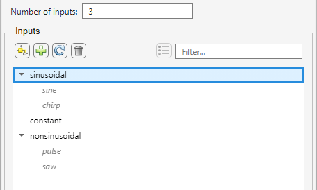
New design for editing Bus Creator block parameters in the Property Inspector

Relational Operator and Logical Operator blocks support Inherit: Inherit via back propagation

The Relational Operator and Logical Operator blocks now support the option Inherit: Inherit via back propagation for the Output data type parameter.

Signal Editor block updates

Starting in R2025a, the Signal Editor block has these updates:

  • The Interpolate data parameter is now enabled by default.

    Note

    If the Signal Editor block is the source for a new Simulink Test or Simulink Design Verifier™ test harness model, the Interpolate data parameter is off by default.

  • The new Use properties from lets you specify the source of signal property definitions.

Blockset Designer updates

The Blockset Designer has these changes:

  • Blocks may now have library block names that differ from their implementation block name. The implementation block name is the name assigned to the block when it is originally authored.

    To change the library block name in the top-library and sublibraries, in the Blockset Browser pane, right-click the block and select Rename.
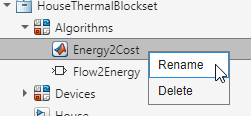
    Block rename

    For more information, see Change Library Block Name.

  • To change the implementation block name, click the Edit button of the Block Path parameter.

    Blockset Designer Edit button for implementation block

    For more information, see Change Implementation Block Name.

Lookup Table blocks update

The Remove protection against out-of-range input in generated code parameter has been replaced by the Assume input is within range parameter for these blocks. The programmatic name, RemoveProtectionInput, remains the same.

For the Interpolation Using Prelookup block, the Remove protection against out-of-range index in generated code parameter has been replaced by Assume index is within range. The programmatic name, RemoveProtectionIndex, remains the same.

For simulation, these changes now cause out-of-range input or index values to always be flagged. This change lets you identify modeling issues before code generation. In releases prior to R2025a, out-of-range input or index values were clipped. If the input was below the lower boundary, the input value was changed to be the same as the lower boundary of the valid input range.

Code generation behavior does not change.

Change parameter value by selecting from list of options on Radio Button block

Starting in R2025a, you can model radio buttons using the Radio Button block from the Customizable Blocks library. The Radio Button block controls the value of the connected parameter. For information about how to connect the block, see Connect Dashboard Blocks to Simulink Model.

Selecting a radio button option assigns the value associated with that option to the connected parameter. To select an option on the Radio Button block during simulation, click the icon or text of the option you want to select. To select an option when the simulation is not running, click the Radio Button block to select the block, and then click the option icon or text.

You can customize the Radio Button block from the Customizable Blocks library using the Design tab in the Property Inspector.

  • Change the value that each option assigns to the connected parameter.

  • Change the text and the font color of the option labels.

  • Add or remove options.

  • Change the icon that represents a selected or cleared radio button.

  • Change on which side of the label the icons are located.

  • Add a border around the list of options and a title above the list.

  • Change the border thickness and the color of the border and title.

  • Add a background image to the block, or choose a background color.

  • Add a foreground image to the block.

Radio Button block

Change parameter value by selecting from options in drop-down list of Combo Box block

Starting in R2025a, you can model combo boxes using the Combo Box block from the Customizable Blocks library. The Combo Box block controls the value of the connected parameter. For information about how to connect the block, see Connect Dashboard Blocks to Simulink Model.

Selecting an option from the combo box drop-down list assigns the value associated with that option to the connected parameter. To select an option during simulation, click the Combo Box block to expand the drop-down list, and then select the option. To select an option when the simulation is not running, click the Combo Box block to select the block, click the block again to expand the drop-down list, and then select the option.

You can customize the Combo Box block from the Customizable Blocks library using the Design tab in the Property Inspector.

  • Change the value that each option assigns to the connected parameter.

  • Change the text and the font color of the option labels.

  • Add or remove options.

  • Change the chevron icon of the drop-down list.

  • Change the number of visible entries in the drop-down list.

  • Change the background color and border color of the drop-down list.

  • Change the colors of the background, border, and font of the highlighted entry in the drop-down list.

  • Add a background image to the block, or choose a background color.

  • Add a foreground image to the block.

Combo Box block

Push callback button with one click instead of two when simulation is not running

When a Simulink block from the Dashboard or Customizable Blocks library is active, you can interact with the gadget the block represents. For example, you can push a button or flip a switch. When a block is inactive, you can only interact with the block. For example, you can move or resize the block. To interact with the gadget when a block is inactive, you can temporarily activate the block by clicking the block. When you deselect the block, the block becomes inactive again.

By default, all blocks from the Dashboard and Customizable Blocks libraries are active during simulation. Blocks promoted to a dashboard panel are also active when the panel is open in its own window or docked and unlocked. In previous releases, the blocks are inactive in all other cases. Specifically, when the simulation is not running, a Callback Button block in the model canvas or in a panel that is neither open in its own window nor docked and unlocked is inactive. To push the button, you must click the block twice: once to temporarily activate the block, and once to push the button.

Starting in R2025a, Callback Button blocks for which at least one of the callbacks triggered by pushing the button has a nonempty value are always active, regardless of whether the simulation is running. This change means when the simulation is not running, you can push callback buttons with a single click. When the simulation is not running, you can move and resize active Callback Button blocks.

There is also a new keyboard shortcut for interacting with active blocks. Clicking an active Callback Button block or an active block from the Dashboard or Customizable Blocks library that is connected to a parameter or variable value both selects the block and interacts with the gadget the block represents. For example, clicking an unselected active connected Push Button block both selects the block and pushes the button. You can now select the block without interacting with the gadget by pressing Shift and then clicking the block. Similarly, you can open the Block Parameters dialog box by pressing Shift and then double-clicking the block.

Updated dashboard panel deployment process generates smaller app files

The process for deploying dashboard panels as standalone or web apps is changing in R2025a. The updated deployment process generates apps with smaller file sizes. For information about the updated process for deploying apps, see Deploy Dashboard Panel as App.

Limit data logged by Record block

Limit the size of data logged by the Record block by specifying signal values to log. You can specify signal values to log using two new parameters:

  • Decimation — Log every nth signal value.

  • Limit data points to last — Log only the last n signal values.

Export data to a Parquet file using the Record block

Use the Record block to export data from scalar and multidimensional signals, as well as data from buses or arrays of buses, to a Parquet file. The Record block logs and can export real and complex data of any built-in data type, as well as enumerations, strings, and fixed-point data. The Record block can also export messages to a Parquet file as double values. When exporting to a Parquet file, you can configure shared or individual time columns, set row groups by height or size, and choose the compression used when saving the file.
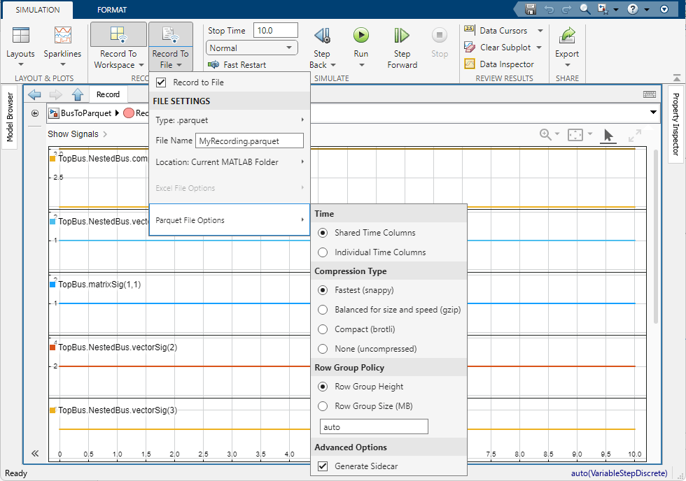
The Record block with the Record To File menu open to show the Parquet File Options menu.

View a table of data in the Playback block

Before R2025a, data added to the Playback block could only be visualized in a sparklines visualization. Now, you can view plotted signals in a table. The Playback block table supports real or complex signals with fixed or variable dimensions, enumerations, strings, discrete and continuous signals, messages, multidimensional signals expanded to channels, buses, and arrays of buses.

The Playback block with a two plot layout. In the upper subplot, the Cosine Wave, Line, and Sine Wave signals are plotted in a sparklines visualization. In the lower plot, these signals are displayed in a table.

MATLAB System block supports unbounded variable-size signals

Starting in R2025a, the MATLAB System block supports unbounded variable-size signals.

C Function block: Support for Simulink strings

Starting in R2025a, C Function block input and output ports support Simulink strings. To specify Simulink strings for a port, set the corresponding symbol data type to string in the Ports and Parameter Symbols table. For more information, see Port and Parameter Symbols.

C Function block: Code coverage support for local custom code

Starting in R2025a, the C Function block supports code coverage for custom code that is locally specified in the block dialog box. To locally specify your C/C++ code in the C Function block dialog box, use the Simulation Custom Code and the Code Generation Custom Code in the Simulation section and the Code generation section, respectively. For more information, see Configure custom code settings.

If block: New expression table and expression editor

Starting in R2025a, the If block has a new Expressions table with action buttons that allow you to manually add, remove, and move expressions. In the new table, each row represents an else if expression, making it easy to visualize and parse. Previously, the block had a single Elseif expression field containing comma-separated list of all the else if expressions.

Additionally, the new Expression editor box allows you to edit complex expressions.
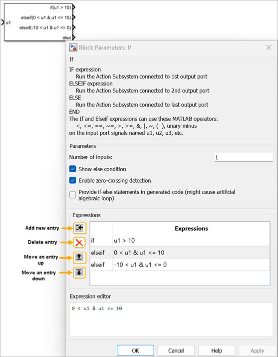
Updated expression fields and new expression editor forIf block.

If block: Include if-else statements in generated code

Starting in R2025a, the new Provide if-else statements in generated code parameter allows you to include if-else statements in the code generated from an If block. Selecting this parameter prevents inclusion of switch-case statement in the generated code and enhances readability of the code.

Neighborhood Processing Subsystem, Array Processing Subsystem, and Pixel Processing Subsystem blocks support MATLAB Function blocks

Starting in R2025a, you can use MATLAB Function blocks inside Neighborhood Processing Subsystem, Array Processing Subsystem, and Pixel Processing Subsystem blocks. Use MATLAB Function blocks to implement neighborhood processing algorithms, such as those that perform image processing tasks, in MATLAB code.

Use cross-port parameter constraints to establish relationships among ports and parameters within the same masked block

Create constraints among the ports and parameters within the same masked block. For example, you can constrain the data type of an input port signal and an edit parameter. Create constraints using the predefined rules such as Same Data Type, Same Dimensions, and Same Complexity and then associate the ports and parameters to the constraints.

To create cross-port parameter constraints, in the Mask Editor, click Constraints, specify the name of the constraint, set the rules, parameter conditions, and associate the ports and parameters appropriately. For more information Validate Port Signals and Parameter Values Using Cross Port Parameter Constraints.

Create a structure of mask parameters to simplify tuning

Starting in R2025a, you can create structure of mask parameters and associate it with the masked block to simplify parameter tuning and data management.

To create a structure containing parameter names and their current values for any masked block, use get_param with the argument ParameterValuesStruct.

<structName> = get_param(<blockName or handle>,"ParameterValuesStruct")

To associate a structure that contains parameter names and values with a masked block, use set_param with the ParameterValueStructname-value argument.

set_param(<blockName or handle>,"ParameterValuesStruct","<structName>")

For parameters which do not support variable names as values like popup, radio button and checkbox, set the parameter value in the struct and then use the set_param function.

For multiple masked blocks within a model, create nested structure. To create and associate a nested struct as per the model hierarchy, use the set_param with the model name as an input argument.

set_param(modelName,"ParameterValuesStruct","<structName>")

Nontunable parameters of a child block can no longer refer to a tunable mask parameter of its parent

Starting in R2025a, the value of a nontunable parameter of a child block cannot refer to a tunable mask parameter of its parent. An error is displayed when you attempt to edit the value of the child block's parameter.

Search and filter mask parameters and their prompts in Mask Editor

Use the Parameters and Dialog pane of the Mask Editor to search and filter parameters, dialog controls, and containers based on name or prompt. Refine the search results based on mask parameter properties, such as Type, Evaluate, Tunable, and Visible.
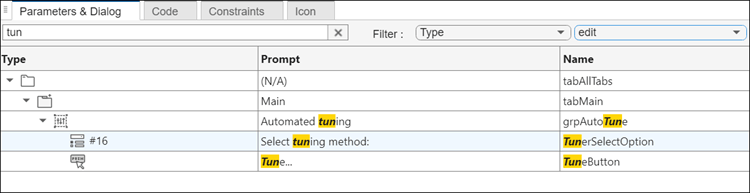
Parameters and dialog tab of Mask Editor showing the filter and search fields.

Enhancements to mask enumeration parameters referring to external enumerations

Starting in R2025a, mask enumeration parameters referring to external enumeration class support enumeration classes derived from int32, int16, int8, uint32, uint16, and uint8 as well apart from the existing enumeration classes. You can also reference enumeration classes derived from Simulink.IntEnumType and Simulink.Mask.EnumerationBase inside namespaces as the options of a popup parameter.

Mask parameter callback execution is optimized

Starting in R2025a, Simulink optimizes the execution of mask parameter callbacks. It no longer re-executes a parameter callback if it has already run once when opening the mask dialog box. Previously, all mask parameter callbacks were executed each time you opened the dialog box.

Enhancements to Graphical Icon Editor

Graphical Icon Editor has these enhancements:

  • Integrated view of visibility conditions on a block icon— Access a unified view of all visibility conditions on a block icon in the Condition Editor window. In the Dynamization section of the toolstrip, click Edit Condition to view and edit the visibility condition. Additionally, search for specific conditions using the search box.
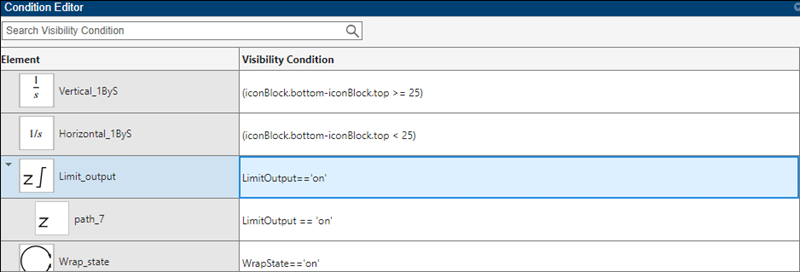
    Condition Editor window showing visibility conditions of an integrator block

  • Rename a masked block icon— Use the Save As option on the Graphical Icon Editor toolstrip to rename a masked block icon.

  • View an enhanced preview of masked block icon— The preview feature is enhanced with improved grid lines, annotations, and other options to visualize icons against different Simulink canvas colors.

  • View all icon parts in a block icon— Click view all parts iconin the Element Browser for an integrated view of all the parts in a block icon. To edit a specific part, double-click the part.
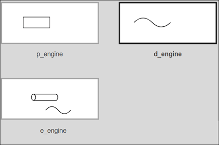
    Icon canvas showing all parts of a block icon

Add hidden properties of a System object class file to the Mask Editor

Use the Base Class Property parameter in a System object mask to add hidden properties of a system object class to the Mask Editor. The property continues to be hidden in the mask dialog.

Table properties in system object class translates to custom table in Mask Editor

Starting in R2025a, table properties in system object class translates to custom table parameter in system block mask.

String values now supported as model arguments

Simulink.Parameter objects and MATLAB variables with string values in a model workspace can now be configured as model arguments.

Enhancements for deploying and simulating FMU with constant periodic clocks

In R2025a, FMU blocks with constant periodic clocks are enhanced for simulation and performance. You can now:

  • Generate code for models containing the FMU.

  • Simulate models with the FMU in rapid accelerator mode for faster simulation speeds.

  • Include the FMU in a model reference and simulate it in accelerator mode, allowing for greater modularity and faster simulation performance.

  • Create hierarchical model designs by generating nested FMUs.

Generate code for FMU from its source code

Starting in R2025a, you can generate code for an FMU generated from Simulink using its packaged source code. Source-code based code generation is the default setting for nested FMUs, ERT target, GRT target, and rapid accelerator simulation mode. Before R2025a, the generated code for an FMU had a dependency on its platform-specific compiled binary file.

Note

This feature applies only to FMUs generated from Simulink from R2025a onwards. It is not supported for FMUs generated from Simulink prior to R2025a or for FMUs generated by other tools.

To generate code based on the source code of your FMU, in the Code Generation tab of the FMU block dialog, set the Call FMU function using option as source code.
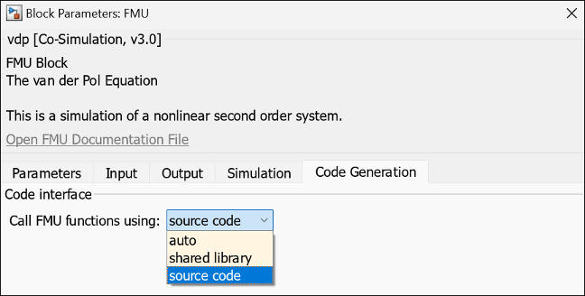
FMU block dialog with call FMU function using set to source code

String to Enum block generates more efficient code

The String to Enum block now generates more efficient code for enumerations by generating a shared function for each enumeration type. Prior to R2025a, this block generated inlined code for enumerations.

Import and simulate FMUs with windows 32-bit DLLs

You can now import and simulate FMUs containing windows 32-bit DLLs in Simulink using the FMU block. To do so, in the Simulation tab of the FMU block dialog, set the Simulate FMU using: parameter as x86-windows.
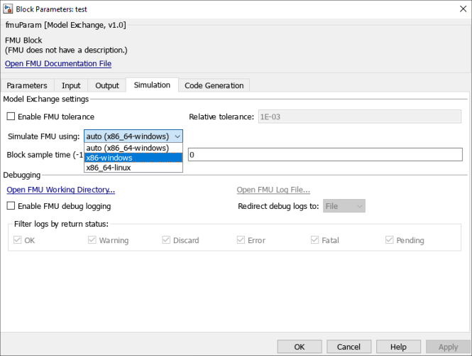
FMU block dialog with simulate FMU using drop-down selecting x86-windows

Generate test harness models for blocks in Python Importer

Starting in R2025a, you can select whether to generate test harness models for blocks in Python Importer. Use the test harness model to run tests and validate the block that imports your specified python code.

To enable generation of test harness, in the Python Importer wizard's Create Simulink Library page, select Automatically create test harness for all imported functions option.

Note

This feature requires the Simulink Test license.
Python importer with test harness creation selected

Extract Bits block update

The Extract Bits block Number of bits and Bit indices parameters now accept only scalar positive integers.

Import FMU with calculated parameters

The FMU block now supports import of calculated parameters. The values of these parameters are derived from other parameters or are determined at run-time. You can see the calculated parameters of an FMU in the Parameters tab of the FMU block dialog.

 Functionality being removed or changed

Access to Simulink Scope through MATLAB Graphics API has been removed

The underlying graphics of the Simulink Scope block have changed. You cannot access or modify the Simulink Scope block through the MATLAB Graphics API.

To display the scope data in a MATLAB Graphics window, use the Print to Figure functionality in the Scope tab of the Scope block toolstrip.

Floating Signal Selection has been removed

The floating signal selection feature (Lock button used to enable the selection of multiple signals) in the Floating Scope block has been removed. To connect signals to your floating scope, use the existing signal selector (signal selector icon on floating scope) instead. For more details, see Add Floating Scope Block to Model and Connect Signals.

Ability to dock Scopes to MATLAB desktop has been removed

The ability to dock the Simulink Scope and Floating Scope and Scope Viewer to the MATLAB desktop has been removed. Use the new scope container instead. For more information, see Scope Window Management.

If you have a model created in R2024b or a previous release with four or more open scopes, and you open that model in R2025a, the opened scopes automatically dock in the scope container window.

Lookup Table blocks Remove protection against out-of-range input in generated code parameter replaced

The Remove protection against out-of-range input in generated code parameter has been replaced with Assume input is within range for these blocks. The programmatic name, RemoveProtectionInput, remains the same.

For the Interpolation Using Prelookup, the Remove protection against out-of-range index in generated code parameter has been replaced by Assume index is within range The programmatic name, RemoveProtectionIndex, remains the same.

If the model simulation generates errors because the out-of-range input or index is fed to a block with Assume input is within range or Assume index is within range selected, the code generated by the model has undefined behavior when the same out-of-range input or index occurs during execution of the generated code. This undefined behavior might cause severe issues. For safety critical applications, do not select Remove protection against out-of-range input in generated code or Remove protection against out-of-range index in generated code.

In releases prior to R2025a, the Remove protection against out-of-range input in generated code and Remove protection against out-of-range index in generated code only removed the code checks for out-of-range values for generated code. The block did not generate an error if an out-of-range input or index was fed to the block during simulation. As a workaround. if you have a model from a release prior to R2025a, cannot migrate to a later release, and want to detect the out-of-range issue, set the Diagnostic for out-of-range input parameter to Error. The next time you run the model, the block generates an error when the input or index is out-of-range.

Function-Call Generator block no longer behaves as masked block

Behavior change

Starting in R2025a, the Function-Call Generator block no longer behaves as masked, linked block. The block now behaves as a built-in block and executes faster during simulation.

When you update from another release to the R2025a, you must fix any Function-Call Generator block whose link to the Simulink library is broken. Otherwise, the block will not be updated, and it will continue to behave as a masked block in the updated model. The masked behavior of the block will be removed in a future release.

Bus Creator block Require names of inputs to match names above and Rename selected signal parameters have been removed

The Require names of inputs to match names above and Rename selected signal parameters of the Bus Creator block have been removed. To specify the required names, use a Simulink.Bus object instead.

Setting Inputs to a comma-separated list of element names is not recommended.

For more information, see Bus Creator.

Change in syntax to preserve tunability in generated code for parameters that are modified or created in mask initialization code

Behavior change in future release

The syntax to create or update mask workspace variables using mask initialization code to preserve tunability of parameters in generated code is changed.

Previously, you were using

maskWorkspace.set("newParam","myFile.update","maskParam1", "maskParam2",constVal)

Starting in R2025a, use

maskWorkspace.set ("newParam", @()myFile.update(maskParam1, maskParam2,constVal))

Neighborhood Processing Subsystem block no longer supports blocks that have state

Still runs

Starting in R2025a, the Neighborhood Processing Subsystem cannot contain blocks that have state.

Connection to Hardware

Arduino Hardware: Support for Arduino UNO R4 Minima, UNO R4 Wi-Fi, and Nano RP2040 Connect boards in Simulink Online

You can now use Simulink Support Package for Arduino Hardware in Simulink Online™ to create, run, and deploy Simulink models on these Arduino boards through your web browser:

  • Arduino UNO R4 Wi-Fi

  • Arduino UNO R4 Minima

  • Arduino Nano RP2040 Connect

For more information, see Get Started with Simulink Online for Arduino.

Arduino Hardware: Deploy code on Arduino boards over Wi-Fi using OTA technology

Starting in R2025a, use Simulink Support Package for Arduino Hardware to deploy code for a Simulink model over a Wi-Fi network on these boards:

  • Arduino MKR Wi-Fi 1010

  • Arduino MKR 1000

  • Arduino Nano 33 IoT

  • Arduino Uno R4 Wi-Fi

Over the Air (OTA) technology enables deploying code over a Wi-Fi network, eliminates the need for USB cables or any other wired connections, and provides greater flexibility in code deployment workflows. For more information, see Implement Over-the-Air Programming with Arduino and Set Up and Upload Arduino Simulink Models Over the Air.

Arduino Hardware: Connected IO and PIL mode and Input Capture block support for Teensy boards

Starting in R2025a, Simulink Support Package for Arduino Hardware includes the following features for Teensy 4.0 and 4.1 boards that are compatible with Arduino:

Arduino Hardware: Support for Arduino Uno R4 Minima hardware board

Starting in R2025a, you can deploy Simulink models containing the following blocks from Simulink Support Package for Arduino Hardware to the Arduino Uno R4 Minima board. You can select this board in the Hardware board drop-down list in the Configuration Parameters dialog box.

Simulink Support Package for Arduino Hardware includes the following features for the Arduino Uno R4 board:

For more information, see Supported Arduino Hardware.

Arduino Hardware: Enable pin multipurposing on RP2040 and PICO boards

Starting in R2025a, use any of the general-purpose IO pins of RP2040 and PICO boards compatible with Arduino to configure the SPI, UART, and I2C protocols. In earlier releases, you could configure these protocols using only the peripheral pins designated for the protocols. For more information, see Serial port properties, I2C properties, and SPI properties.

Arduino Hardware: Enable PIL support for RP2040 Connect boards

Starting in R2025a, you can deploy a Simulink model in the processor-in-the-loop (PIL) mode on your Arduino Nano RP2040 Connect board. For more information, see Code Verification and Validation with PIL on Arduino Hardware.

Arduino Hardware: Connected IO, PIL, servo blocks, and PWM support for Arduino Uno R4 Wi-Fi Boards

Starting in R2025a, Simulink Support Package for Arduino Hardware includes the following features for the Arduino Uno R4 Wi-Fi board:

 Functionality being removed or changed

Raspberry Pi Hardware: Network CAN capabilities for Raspberry Pi

Behavior change

Starting in R2025a, you can enhance the controller area network (CAN) capabilities of a Raspberry Pi board using Raspberry Pi Blockset. You can configure a maximum of five CAN interfaces with properties such as CAN interface type, CAN bus speed, and transmit queue buffer size in the Configuration Parameters dialog box. In the earlier releases, you could configure these parameters in the block mask of the CAN Receive and CAN Transmit blocks. For more information on configuring the CAN interfaces, see CAN properties.

Raspberry Pi Hardware: Raspberry Pi – Robot Operating System (ROS) option will be removed from Configuration Parameters

Behavior change

The Raspberry Pi – Robot Operating System (ROS) option in the Configuration Parameters > Hardware Implementation > Hardware board will be removed in a future release. This removal was last announced in R2020b. For Simulink models that use Raspberry Pi – Robot Operating System (ROS) as the default target, change the target to Robot Operating System (ROS).

Raspberry Pi Hardware: Support for Buster Raspberry Pi Linux operating system will be removed

Still runs

Support for the 32-bit Buster Raspberry Pi Linux operating system will be removed in a future release for Raspberry Pi Blockset in the Simulink desktop and Simulink Online environment. You will no longer be able to use the support package to communicate with a Raspberry Pi board that runs a Buster operating system. You must upgrade the Raspberry Pi Linux operating system to 32-bit or 64-bit Bullseye or Bookworm in the Simulink desktop environment and 32-bit Bullseye or Bookworm in the Simulink Online environment. For more information on how to set up an operating system on your Raspberry Pi hardware, see Set Up Operating System on Raspberry Pi Board.

MATLAB Function Blocks

Code generation for more toolbox functions

In R2025a, you can generate code for many additional toolbox functions and objects. For a list of all functions and objects that are supported for code generation, see:

These are links to the release notes of some toolboxes that added code generation support in R2025a:

Image Processing Toolbox

See C Code Generation: Generate code from additional functions using MATLAB Coder.

Statistics and Machine Learning Toolbox

See Generate C/C++ code for performing incremental learning using multiclass classification model functions (requires MATLAB Coder).

Modeling Guidelines

Modified modeling guidelines

Starting in R2025a, the modeling conditions C and D have been removed from the High-Integrity System Modeling guideline hisl_0008: Usage of For Iterator Blocks. It no longer supports the following control display configuration parameters:

  • Set Next i (iteration variable) externally

  • Show iteration variable

Updated guideline about code generation for data stores and states using persistent data

Starting in R2025a, the code generation modeling guideline cgsl_0411: Access nonvolatile memory is updated to contain information about using a measurement service interface for persistent data.

S-Functions

Enhancements to the S-Function Builder block editor

Starting in R2025a, the S-Function Builder block editor has these updates:

  • You can now save your editor session using the Save button.

  • Use the Set Output option to specify the desired output directory for the generated S-function files.

  • The Settings pane is divided into general settings and settings specific to S-Function.
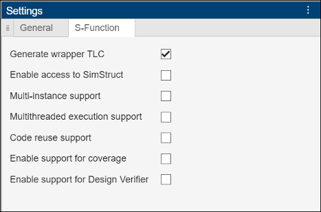
    Code Builder S-Function settings

Code Builder editor for s-function builder block

R2024b

New Features, Bug Fixes, Compatibility Considerations

 Learn about Simulink blocks and actions using quick insert menu details pane

You can now learn more about Simulink blocks and actions using the quick insert menu details pane.

To access the details pane for a block, double-click the Simulink canvas. To access the details pane for an action, press Ctrl+. (on macOS, press command+.). The quick insert menu appears. In the search box, type the name of the block or action. Using arrow keys, navigate to a search result. View the details pane to the right of the list of search results.

Use the content of the details pane to complete these tasks.

TaskHow to Complete Task
Open the block library.Click the hyperlink under the block name. If a block is in multiple libraries, you might see multiple hyperlinks.
Determine whether a block or action is the one you are looking for (there can be multiple different blocks with the same name).Read the description of the block or action.
If you can take an action using the Simulink Toolstrip, determine where in the toolstrip you can take the action.Follow the instructions under the description. For example, for the Auto Arrange action, the instructions are FORMAT/Auto Arrange. To take the action, in the toolstrip, on the Format tab, click the Auto Arrange button.
Look up information about a block.Click Learn More.
Learn about related blocks and topics.Click the hyperlinks under See Also.
View an example of how to use a block.Click the hyperlinks under Examples.

To hide the details pane, click the arrow . To show the details pane, click the arrow again.
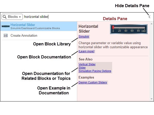
The quick insert menu is open and shows the details pane for the Horizontal Slider block.

Switch between searching for blocks and searching for actions in the quick insert menu

In the quick insert menu, you can switch between searching for blocks and searching for actions by pressing Ctrl+. (on macOS, press command+.). Starting in R2024b, you can also switch between searching for blocks and searching for actions using the drop-down list in the upper left corner of the quick insert menu.

To open the quick insert menu, double-click the canvas or press Ctrl+.. When you open the menu by double-clicking the canvas, by default, you can search for blocks. When you open the menu with the keyboard shortcut, by default, you can search for actions.

If you open the menu by double-clicking and want to search for actions, in the upper left corner of the quick insert menu, expand the drop-down list with the search icon and select Actions.

If you open the menu using the shortcut and want to search for blocks, expand the drop-down list and select Blocks.
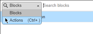
Upper left corner of the quick insert menu, with the drop-down list expanded

Explore more MathWorks models with Model Finder

Previously, Model Finder search results included only those examples, models, and projects from the MathWorks Examples database for which you had the MathWorks toolbox licenses required for these examples to work correctly. Starting from R2024b, you can also explore the examples without having the toolbox licenses.

However, to simulate a model, you need the recommended toolbox licenses. For details on toolboxes and how to install them using the Add-On Explorer, click a license name in the Information pane of Model Finder. For information on managing MathWorks products using the Add-On Explorer, see Get and Manage Add-Ons.

Simulation Analysis and Performance

 Save Simulation Data Inspector sessions more efficiently with the new MLDATX 2.0 file format

Save Simulation Data Inspector sessions with a faster save time and smaller file size using the new MLDATX 2.0 file format. Specify the compression and version of the session file using the new Save Session dialog box or the new name-value arguments for the Simulink.sdi.save function. You can choose from one of these compression options:

  • Fastest — Similar save speed to an uncompressed file, smaller file size

  • Balanced — Balance between file size and save speed

  • Compact — Smallest file size, slowest save speed

  • None — Largest file size, fastest save speed

To see which version your MLDATX file is, use the Simulink.sdi.getVersion function.
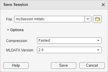
The Save Session dialog

Debug simulations on demand by stepping block by block

When the Pause within time step option is selected in the Breakpoints List, you can now start debugging a simulation on demand by stepping through time steps block by block. In previous releases, you could step block by block through a time step only when the simulation was paused and only if the model contained an active breakpoint before you started the simulation.

With on-demand simulation debugging, you can now debug a simulation by stepping block by block from the beginning of the simulation and without first adding a breakpoint. To start a simulation by stepping block by block, in the Simulink Toolstrip, on the Debug tab, click Step Over. The simulation starts and then pauses just before executing the first block in the execution order. To control the simulation execution while debugging, you can:

  • Step block by block by clicking Step Over.

  • Add breakpoints to conditionally pause the simulation.

  • Step through time steps by clicking Step Forward and Step Back.

  • Pause or resume on demand by clicking Pause or Continue.

For more information, see Step Through Simulations Using the Simulink Editor.

Add signal breakpoints during simulation runtime

You can now add signal breakpoints to a model while a simulation of the model is running. In prior releases, you could add signal breakpoints only when the simulation was paused. For more information, see Breakpoints List and Debug Simulation Using Signal Breakpoints.

Add signal breakpoints and port value labels to iteration number outputs in iterator subsystems

You can now pause a simulation on a particular iteration of an iterator subsystem by adding a signal breakpoints on signals produced by:

In previous releases, you could add a breakpoint in these locations, but the breakpoints did not pause the simulation and appeared as invalid in the block diagram.

Port value labels now display the iteration number at the same locations. In previous releases, port value labels at these locations showed inaccessible.

For an example, see Debug Simulation of Iterator Subsystem.

C++ code generation support for implicit systems

You can now generate C++ code from models that represent or contain implicit systems, such as those implemented using the Descriptor State-Space block or Simscape blocks. Prior to R2024b, implicit systems supported only C code generation. Use the Language (Simulink Coder) parameter to specify the language for code generation.

Build App Designer apps for Simulink models using improved interactive tools

Starting in R2024b, you can build apps for Simulink models in App Designer more efficiently using these enhancements:

  • Get started quickly by using an interactive tutorial that guides you through each step of the app building process. On the App Designer start page, click Show examples in the Simulink Apps section and select Simulink App Tutorial.

  • Validate and filter bindings between UI components and model elements. Validate bindings by clicking Validate Bindings on the Simulink tab of the App Designer toolstrip, and filter existing bindings using the Bindings tab in the Component Browser.

  • Edit time scope labels interactively in Design View. Double-click the label text and enter a value.

For more information, see Create App for Simulink Model.

New functions enhance programmatic visualization of data in the Simulation Data Inspector

In R2024b, new functions have been added to improve your ability to programmatically visualize and inspect data in the Simulation Data Inspector.

Log data stores in accelerator and rapid accelerator mode simulations

Log Data Store Memory block variables in accelerator and rapid accelerator mode simulations. You can view and access logged data in the MATLAB workspace and the Simulation Data Inspector.

Analyzing Results in Simulink: Self-paced, interactive course available as part of Online Training Suite subscription

Analyzing Results in Simulink is a new course that teaches you to:

  • Configure a Simulink model to log data that you can view in the Simulation Data Inspector.

  • Visualize and organize logged data in the Simulation Data Inspector using configurable subplot layouts and different visualization types.

  • Customize signal appearance and use cursors to inspect and analyze data in the Simulation Data Inspector.

  • Compare signals and runs by configuring comparison constraints and specifying signal tolerances and global tolerances.

  • Save the Simulation Data Inspector session to share your simulation results and customized visualizations with others.

For more information, see Analyzing Results in Simulink.
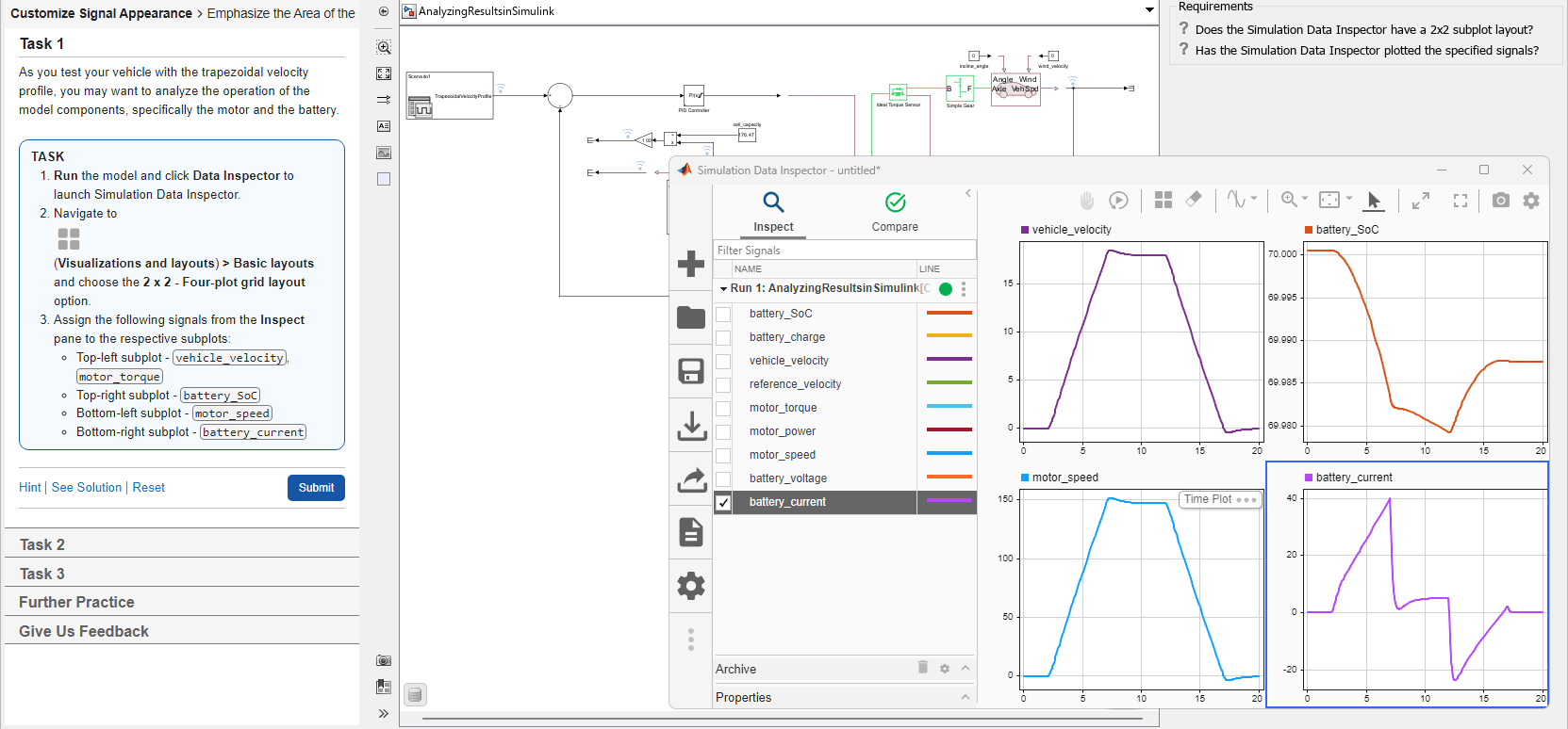
Analyzing Results in Simulink describes the task, displays an interactive model, and assesses whether the model matches the requirements set by the training.

 Functionality being removed or changed

Objects functions for the Simulink.ModelDataLogs object functions and support for converting ModelDataLogs data to Dataset format have been removed

Errors

Support for the ModelDataLogs format is limited. These Simulink.ModelDataLogs object functions have been removed:

Additionally, the Simulink.SimulationData.Dataset object can no longer convert ModelDataLogs format to Dataset format. To convert data logged in ModelDataLogs format to Dataset format, use a version of Simulink prior to the R2024b release.

Support for ModelDataLogs format will be removed

Warns

Support for the ModelDataLogs format is limited. In R2024b, Simulink.ModelDataLogs object functions and the ability to convert ModelDataLogs data to Dataset format have been removed. In R2016a, the ability to log data using the ModelDataLogs format was removed. Since R2022b, loading ModelDataLogs data is not supported.

In a future release, support for ModelDataLogs format, including the Simulink.ModelDataLogs, Simulink.Timeseries, Simulink.TSArray, and Simulink.SubsysDataLogs objects, will be removed.

sltrace function no longer opens model

Behavior change

To better support scripting workflows, the sltrace function now loads models instead of opening them. The highlight and removeHighlight functions still open the model to show the highlighted signal trace in the model.

Component-Based Modeling

 Inspect and edit component interfaces using Component Interface View

In the Simulink Editor, you can toggle whether to display component interfaces. The Component Interface View now supports:

  • Adding ports — Click the border that represents the interface of the component. From the action bar, select a port type.

  • Removing ports — Select a port. Then, press Delete.

  • Improved tracing — Select a port. From the action bar, click Show usage. To trace an element of a bus element port, select the element in the Property Inspector.

  • Type editing — Select a port. From the action bar, click Edit types. The docked Type Editor opens.

  • Interactive model editing — Edit the block diagram while you have the Component Interface View open.

To use the Component Interface View, in the Simulink Toolstrip, on the Modeling tab, under Design, click Interface View.

For more information, see Trace Connections and Author Ports Using Component Interface View.
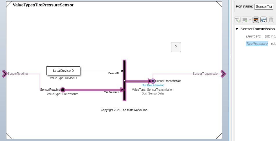
Component Interface View showing usage of an element of a bus element port

 Change the active choice of a Variant Subsystem block during simulation or execution of generated code

In R2024b, you can switch the active variant choice of a Variant Subsystem during simulation or execution of the generated code by using the Parameter Writer block. Select run-time variant activation time when you want to switch between variants in real time. To enable run-time activation of variants, set the Variant activation time parameter in the Variant Subsystem block to runtime. Then use a Parameter Writer block, placed inside a conditionally executed subsystem or in an event function, to write to a variant control variable. The control variable can be in a global workspace, mask workspace, or model workspace.

For more information, see Control Active Choice of Variant Subsystem During Simulation or Execution of Generated Code.

Variant Manager for Simulink: Use model compilation information to improve accuracy of workflow results

Variant Manager now allows you to obtain and use model compilation information to produce more accurate results for user workflows such as activation and importing of control variables to a configuration.

You can obtain model compilation information in Variant Manager by using the new Update Model button in the user interface or programmatically by using the Simulink.VariantManager.updateModel function. For more information, see Obtain and Use Model Compilation Information in Variant Manager.
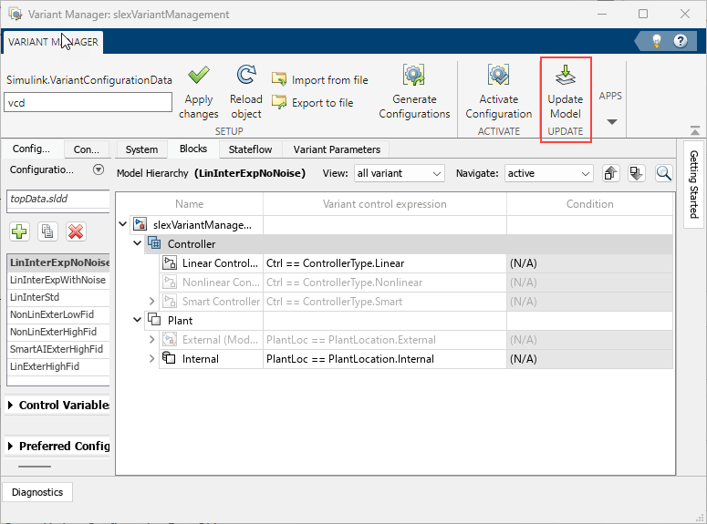
Variant Manager window shows the new Update Model button in the toolstrip

Use custom value types inherited from Simulink.Parameter in Simulink.VariantControl objects

You can now set the Value type property of a Simulink.VariantControl object to a class that derives from the Simulink.Parameter object. For an example, see Custom Data Class Objects as Values of Simulink.VariantControl Objects.

Variant Manager for Simulink: Specify variant configurations for tests from Simulink Test Manager

Starting in R2024b, you can use Simulink Test Manager (Simulink Test) to select the variant configuration to use when running a test case or a test iteration on a model. For an example, see Run Tests for Variant Models Using Variant Configurations.

Variant Manager for Simulink: Import variant controls defined in model data source into Variant Manager

Variant Manager now provides an option to import variant control variables of type Simulink.VariantControl defined in the base workspace or a data dictionary linked to the model even if the variant control is not yet used by the model. In top-down variant management workflows where you may need to define variant configurations before setting up variation points in the model, this operation allows you to access the variant controls that you have already defined in a data source from Variant Manager.

The new import option is available when you open Variant Manager for a Simulink model and also when you open Variant Manager without a model, that is, by double-clicking a variant configuration object in the base workspace or a data dictionary.

  • In the Variant Manager window for a Simulink model, click the down arrow on the Import control variables across model hierarchy button in the Control Variables section to access the Import control variables from model data source option.

  • In Variant Manager opened without a model, in the Control Variables section in the dialog box, click the Import control variables from model data source button.
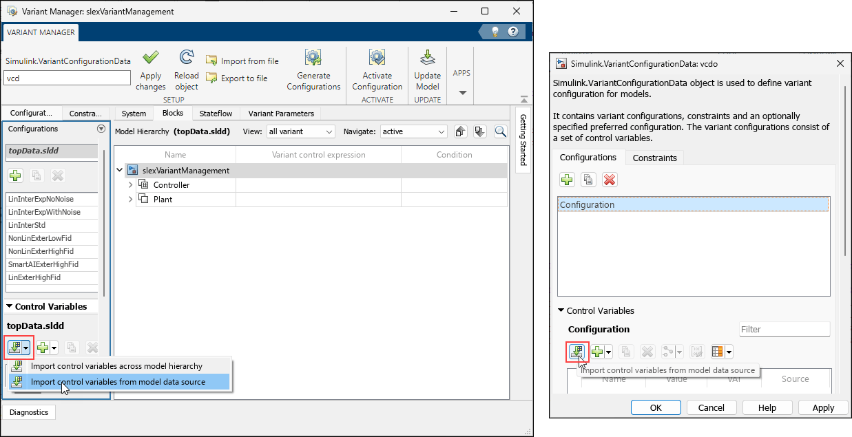
Variant Manager window shows the new import button

Variant Manager for Simulink: View variant parameters without a variant bank in Bank per row view

In the Variant Parameters tab in Variant Manager, the Bank per row view now shows in a separate section variant parameters that are not part of any variant bank. This section groups parameters sharing the same variant conditions together, making it easier to identify parameter groups for association with a variant bank.
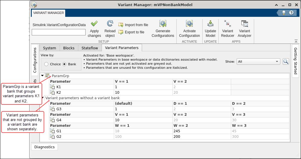
Variant Parameters tab shows parameters that are not grouped by a variant bank

Convert a Subsystem block to a Variant Subsystem block in expression mode

Starting in R2024b, you can convert a Subsystem block to a Variant Subsystem block in expression mode. Convert a Subsystem to a Variant Subsystem in expression mode interactively in these ways:

  • Right-click the Subsystem block and then select Subsystem & Model reference > Convert to > Variant Subsystem.

  • Select the Subsystem block. Then, in the Simulink Toolstrip, on the Subsystem Block tab, click Convert > Variant Subsystem.

In both the ways, you can specify the Variant control mode, Variant activation time, and Variant control expression in the block parameter dialog box. To programmatically convert a Subsystem to a Variant Subsystem block, use the Simulink.VariantUtils.convertToVariantSubsystem method.

Previously, conversion was supported only in the label mode.

open_system Function: Specify more than one argument to open a model, or a subsystem in a new tab or window

Starting in R2024b, you can specify more than one argument to the open_system function as comma separated values to open a model, or a subsystem in a new tab or window. For example, you can open the content in a masked subsystem in a new tab or window or open the active choice of a Variant Subsystem block in a new tab or window using the syntax:

open_system (gcb,'force','window')
open_system(gcb,'ActiveChoice','window')

Previously, it was not possible to open the content of a masked subsystem or open the active choice of a Variant Subsystem in a new window using the open_system function.

Optimize generated code using Simulink.AliasType with update diagram and update diagram analyze all choices

Starting in R2024b, when you use the Simulink.AliasType data type in any external inport or outport blocks which are inactive due to inactive choices of inline variant blocks with variant activation time set to update diagram or update diagram analyze all choices, the generated model header code does not includes the header files associated with the inactive Simulink.AliasTypes.

Enhancements to Variant Start and Variant End blocks

Starting in R2024b, you can:

  • Cascade the Variant Start and Variant End block pairs such that one bounded region encompasses the other.

  • Propagate conditions from variant blocks to the bounded region of the Variant Start and Variant End blocks.

Previously, these resulted in an error.

Customize sample time color palette using new simulink.sampletimes.Palette object

In R2024b, you can use the new simulink.sampletimes.Palette object to add custom colors for all types of sample times in your model. Color palette customization API allows you to create a palette object that you can use for your current MATLAB session as well as set as a preference for all future MATLAB sessions. When you apply a customized palette, it is applied to all open models in the MATLAB session. You can specify different colors for the sample time color palette in hexadecimal or RGB formats.

Create test harnesses for individual components inside a subsystem reference to perform modular testing

You can now create test harnesses for any block within a subsystem reference and test the subcomponents individually to improve fault detection and extend test coverage.

Convert ports to bus element ports more easily

In R2024b, you can more easily convert Inport and Bus Selector blocks into In Bus Element blocks and Outport and Bus Creator blocks into Out Bus Element blocks.

  • The conversion now supports nondefault block parameter values at the corresponding Inport or Outport block. The conversion applies the parameter values to the top-level element of the bus element port.

  • The conversion now supports a signal label between the Inport and Bus Selector blocks or Outport and Bus Creator blocks. The signal label becomes the name of the bus element port.

  • The Simulink Toolstrip now provides a Create Bus Port button on the Modeling tab, in the Component gallery. To enable this button, select a Bus Selector block that connects to an Inport block or a Bus Creator block that connects to an Outport block.

For more conversion information, see Simplify Subsystem and Model Interfaces with Bus Element Ports.

Convert subsystems with mask initialization code to models without forcing conversion

When a masked subsystem has mask initialization code, you can now convert the masked subsystem to a model by using the Model Reference Conversion Advisor. Alternatively, when you use the Simulink.SubSystem.convertToModelReference function to convert the masked subsystem, you no longer need to set Force to true. The system mask of the new model does not use the mask initialization code because system masks of models do not support mask initialization code. For more information, see Introduction to System Mask.

For more information about the overall conversion process, see Convert Subsystems to Referenced Models.

Convert subsystems with mask parameter and cross-parameter constraints to models with those constraints

When you convert a masked subsystem to a model, the conversion now copies the applicable parameter and cross-parameter constraints from the Subsystem block mask to the system mask of the new model. For a constraint to apply to the system mask, the related mask parameters must be available on the system mask. For more information about these constraints, see Validating Mask Parameters Using Constraints.

For more information about the overall conversion process, see Convert Subsystems to Referenced Models.

Convert subsystems with virtual buses to models without wrapper layers or new bus objects

When you convert a subsystem to a model and the subsystem interface uses virtual buses, the block diagram of the new model better mimics the block diagram of the subsystem.

To specify the bus hierarchy without creating Simulink.Bus objects or adding blocks, the new model uses In Bus Element and Out Bus Element blocks. The corresponding bus element ports specify the elements of the bus hierarchy both with and without blocks. For more information, see Specify Multiple Elements of a Port.

For more information about the overall conversion process, see Convert Subsystems to Referenced Models.

Get information from protected model report programmatically

To get high-level information about a protected model, use the new slxpinfo function. The function returns equivalent information to the summary of the protected model report regardless of whether the protected model report is available.

For more information about protected models, see Reference Protected Models from Third Parties.

Add components to model by dragging files into canvas

Starting in R2024b, you can add the components listed in the table to a model by dragging files into the model canvas. The components you create using the drag to add approach are preconfigured to reference the contents of the file you drag. For example, dragging an SLX file into the Simulink model canvas adds a Model block that references the model in the SLX file.

Files that you drag to the canvas must be on the MATLAB path. Creating components by dragging files from the MATLAB Editor into the model canvas is not supported.

ComponentHow to Add Component to Model

Model block

Drag the model file containing the model you want to reference into the Simulink model canvas.

Subsystem block

Drag the subsystem file containing the subsystem you want to reference into the Simulink model canvas.
Reference Component (System Composer) block

Drag the model file containing the model you want to reference or the subsystem file containing the subsystem you want to reference into the architecture model canvas.

The pointer drags the vdp.slx file into a Simulink model named myModel. A Model block appears in the canvas. The pointer double-clicks the Model block. The model in the vdp.slx file opens.

Programmatically connect blocks in different levels of model hierarchy

Starting in R2024b, you can programmatically connect Simulink blocks with signal lines— including blocks at different levels of the model hierarchy— using the Simulink.connectBlocks function. This syntax connects the source specified by src to the destination specified by dst.

connection = Simulink.connectBlocks(src,dst)

The source and destination can either both be specified as blocks or both be specified as ports. If you specify both as blocks, the function connects an unconnected port on the source block to an unconnected port on the destination block. If the source you specify (block or port) is already fully connected, the function branches one of the signal lines connected to the source. If the specified destination is a block, the block must have at least one unconnected port. If the specified destination is a port, the port must be unconnected.

You can specify the blocks or ports using handles or paths. Typically, the port path is the block path followed by a slash and the port number, for example: "myModel/mySubsystem/myBlock/2". To get a port number that is not displayed on the block, in the model, pause your pointer on the port. For more information about specifying blocks and ports, see Get Handles and Paths.

To connect a block with only one output port to a block with only one input port, consider specifying the source and destination as blocks. For example, suppose a model named myModel contains an unconnected Sine Wave block named Input Signal and an unconnected Subsystem block named Plant. The subsystem contains an unconnected Scope block named Scope1. To connect the blocks named Input Signal and Scope1, enter these commands in the MATLAB Command Window.

src = "myModel/Input Signal";
dst = "myModel/Plant/Scope1";
connection = Simulink.connectBlocks(src,dst)

When the model is open, you can undo the connection by pressing Ctrl+Z (on macOS, press command+Z).

For more information about the function, see Simulink.connectBlocks.
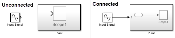
The left half of the image shows the unconnected blocks from the example. The right half shows the blocks after they are connected. A signal line connects the block named Input Signal to the subsystem named Plant. In the subsystem, the Simulink.connectBlocks function added an Inport block. A signal line connects the Inport block to the block named Scope1.

Call synchronous services using function ports in rate-based models

Function Element Call blocks can now be placed in rate-based models to call synchronous services. For more information, see Model Client and Server Components Using Function Ports.

Simulate port-scoped Simulink functions in accelerator mode

Synchronous services modeled using client components with function ports and server components with port-scoped Simulink functions can now be simulated in accelerator mode. You can set the Simulation mode to Accelerator for a top-level model or Model block referencing the client or server component.

For more information on modeling service components, see Model Client and Server Components Using Function Ports.

Automatic synchronization while editing subsystem reference instances

While you edit a subsystem reference instance, all other instances are locked. You must save the modified subsystem reference instance to propagate the changes to all other instances.

Starting in R2024b, some changes to a subsystem reference instance automatically propagate to all loaded subsystem reference instances. For these changes, while editing an instance you can simultaneously observe the same changes in other instances. Automatic synchronization is applicable when you:

  • Add or delete a block.

  • Modify block name, parameter, position, or size.

  • Modify a signal label.

  • Add or modify annotations.

For more information on how to edit and save a subsystem reference, see Reference a Subsystem File in a Model.
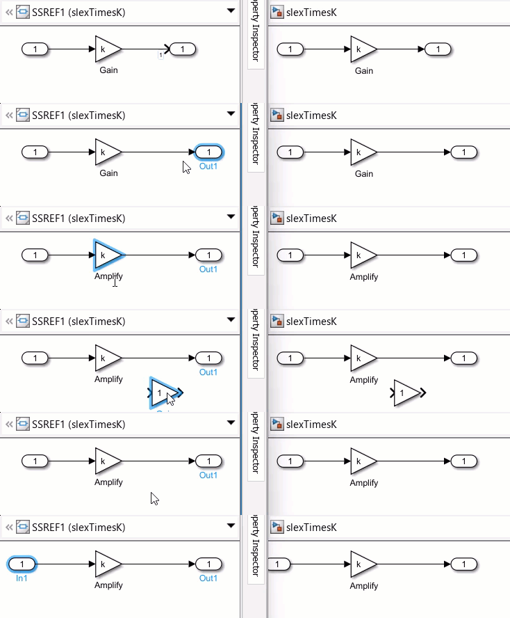
Block diagrams of a subsystem reference instance and a subsystem file with automatic synchronization between both when adding, deleting, or moving a block, or modifying annotation.

 Functionality being removed or changed

Improved sample time propagation for output ports of model references that use local solvers

Behavior change

Model blocks that reference models configured to use local solvers now propagate a discrete sample time to the block output ports if the local solver uses zero-order hold output signal handling. The Communication step size parameter of the Model block defines the discrete sample time propagated to the block output ports. In previous releases, the Model block propagated the sample time of the port in the referenced model to the block output ports.

This change to sample time propagation:

  • Simplifies the interactions between the parent solver and local solver

  • More clearly reflects the effect of the zero-order hold output signal handling in the context of the parent model

  • Reduces the number of parent solver resets

In some cases, the change to sample time propagation causes warnings about sample time discrepancies or collisions. For example, when a Model block output port that now has a discrete sample time drives the input port of another model reference, the software issues a warning if the sample time of the input port in the referenced model does not match the sample time of the input signal in the top model. For more information, see Improve Simulation Performance Using Performance Advisor.

In most cases, this change does not affect numerical results and only results in fewer or different points in logged data for the Model block output signals. The table summarizes the impact of this change for different local solver configurations.

Local Solver Step SizeOutput signal handling Parameter ValueEffect of Sample Time Propagation Change
Local solver step size less than communication step size

Zero-order hold

Model block output ports have a discrete sample time defined by the Communication step size parameter of the block.

The change in sample time does not affect the numerical results of the simulation but can result in different or fewer data points in logged data for Model block output signals in the top model.

Auto

Only zero-order hold output signal handling is supported.

Local solver step size equal to communication step size

Auto

No change to sample time propagation.

Use solver interpolant

Zero-order hold

Model block output ports have a discrete sample time defined by the Communication step size parameter of the block.

The change in sample time can result in different or fewer data points in logged data for Model block output signals in the top model.

In rare cases, the change in sample time can affect numerical results as a result of:

  • Applying the zero-order hold to output signals that do not depend on continuous states in the referenced model

  • Performing fewer parent solver resets

For more information about how local solvers work, see Use Local Solvers in Referenced Models.

Configurable Subsystem block has been removed

Errors

The Configurable Subsystem block has been removed. A Variant Subsystem block offers more advantages than Configurable Subsystems. With Variant Subsystem blocks, you can:

  • Avoid creating a library to instantiate the Variant Subsystem block.

  • Control variant blocks through label, expression, and sim codege switching modes.

  • Include both active and inactive choices in the generated code.

  • Mix Model blocks and Subsystem blocks as variant choices.

  • Easily manage the nested variant subsystem workflow.

  • Use advanced variant management capabilities with Variant Manager.

Convert Configurable Subsystem blocks in existing models to Variant Subsystem blocks by using the Upgrade Advisor. For more information on converting a Configurable Subsystem to a Variant Subsystem, see Convert Configurable Subsystem to Variant Subsystem.

Error reported when Simulink.VariantControl uses Simulink.Parameter object already used in model or in another variant control object

Behavior change

Simulink reports a compile-time error when you try to set the value of a Simulink.VariantControl object to a Simulink.Parameter object that is already used in the model or in another variant control object. For more information, see Error reported when Simulink.VariantControl uses Simulink.Parameter object already used in model or in another variant control object.

Enhanced protection for masked library blocks with locked library links

Behavior change in future release

Looking under the masks of library blocks and Subsystem blocks with links locked to their parent libraries from a Simulink model will not be supported in a future release. To look under the masks of library blocks with locked library links, you must look under the mask of the parent library block. This enhancement prevents accidental changes to your library blocks by concealing the block implementation details.

This change in behavior will apply when you look under the mask of a locked linked block either through the user interface or programmatically by using the open_system(blk,"force") function. Here, blk is the full name or path of the block or subsystem in the open or loaded model.

Check for incompatible and large virtual buses across model reference boundaries

Behavior change

In the Upgrade Advisor, the Check for virtual bus across model reference boundaries check now identifies the root Inport and Outport blocks of referenced models that receive large virtual buses as input. When virtual buses can slow performance, the check returns the affected blocks. The check continues to identify the root Inport and Outport blocks of referenced models that receive incompatible virtual buses as input.

Previously, the check identified only the root Inport and Outport blocks of referenced models that receive incompatible virtual buses as input.

slbuild function will no longer support IncludeModelReferenceSimulationTargets argument

Warns

The slbuild function issues a warning when you use the IncludeModelReferenceSimulationTargets argument. The warning indicates that the argument has no effect and will be removed in a future release.

Project and File Management

 Design Evolution Manager available on MATLAB desktop

The Design Evolution Manager app is now available on the MATLAB desktop, as well as on MATLAB Online. Use the Design Evolution Manager app to:

  • Store alternative versions of files in a project and associated metadata as evolutions to simplify management of your work in progress.

  • Visualize your design process in an evolution tree to see the big-picture trajectory and understand why design decisions were made.

  • Compare and merge different versions of files between any pair of evolutions.

  • Generate a PDF report that summarizes the evolution tree, including the evolution tree hierarchy and metadata.
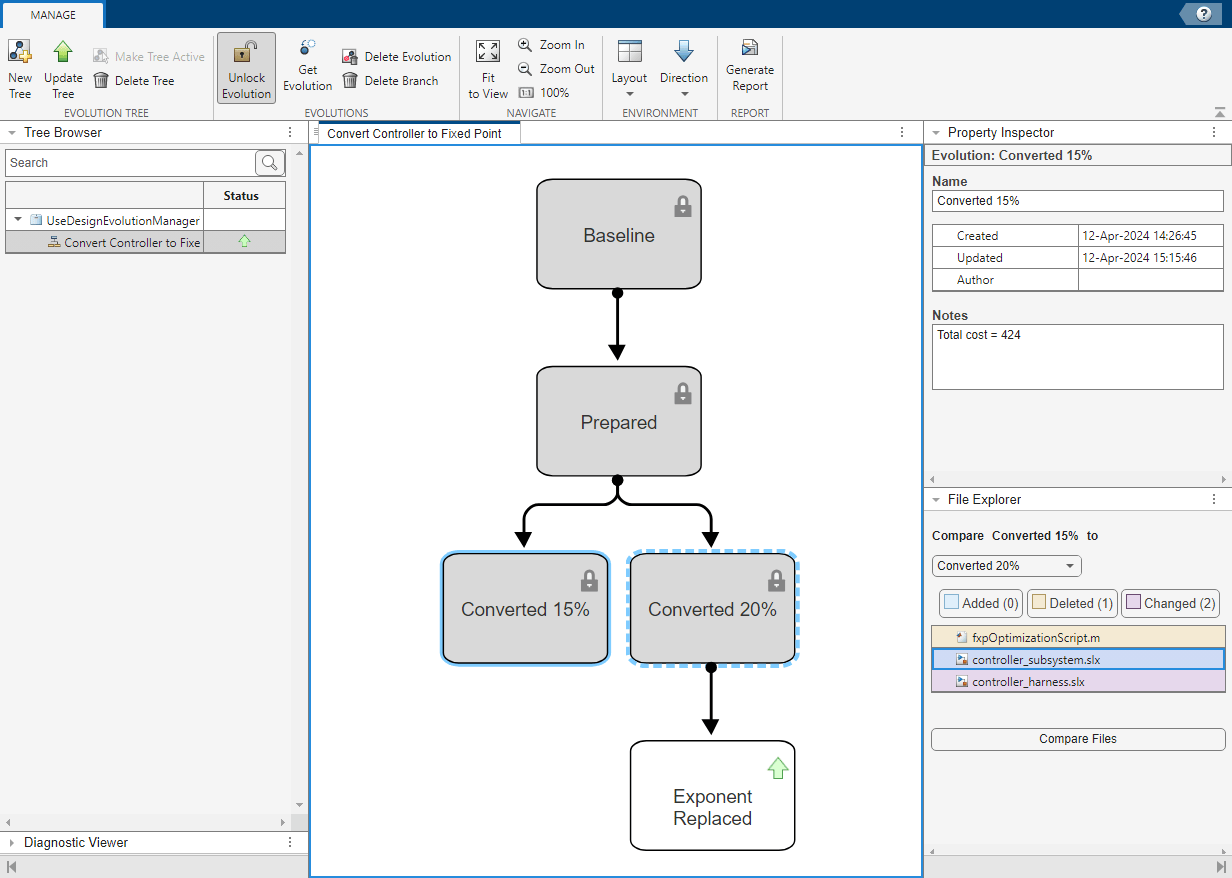
Screenshot of the Design Evolution Manager app in the MATLAB desktop.

Project API: Specify dependency analysis scope

When you analyze a project using the updateDependencies function, you can specify the dependency analysis scope. For example, to analyze dependencies inside add-ons, use updateDependencies(currentProject,AnalyzeAddOns=true).

Project API: Label multiple project files at once

You can programmatically attach a label to multiple project files at once using addLabel. You can also detach a label from multiple files using removeLabel.

Dependency Analyzer: Find required packages and missing package dependencies

When you run a dependency analysis on your code, the Dependency Analyzer lists the required packages in the Add-Ons section of the Properties pane. For more information, see Find Required Products and Add-Ons.

The Dependency Analyzer also flags any missing package dependencies in the Problems section. For more information, see Check Dependency Results and Resolve Problems.
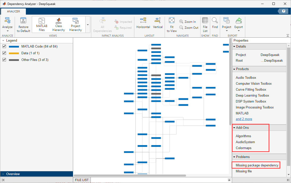
Dependency Analyzer with a toolstrip at the top, Legend pane on the left, Properties pane on the right, and the dependency graph in the middle. The Properties pane includes Details, Products, Add-Ons, and Problems sections.

Simulink Templates: Set default template for subsystems

You can now set a subsystem template as a default to use every time you create a new subsystem. For more information, see Set Default Template for New Models.

The model and subsystem default templates at the top of the options under the New button in the Simulink editor

Simulink Templates Comparison: Compare Simulink template files with improved usability and appearance

You can now easily interpret the model templates comparison results in the comparison report using rich highlighting in the Simulink Editor. For more information, see Compare Model or Project Templates.

Source Control Examples: Use Git hooks in MATLAB

This example shows how to use Git hooks in MATLAB to standardize your commit workflows. See Use Git Hooks in MATLAB.

Source Control in MATLAB Online: Expanded support for Git workflows

MATLAB Online now provides expanded support for Git workflows.

  • Annotate lines in the MATLAB Editor using Git history.

  • Check out a Git branch to a different folder using Git work trees.

Project Issues in MATLAB Online: View and fix project startup and shutdown issues

In MATLAB Online, you can view all issues that occur during project startup and shutdown using the Project Issues panel. When possible, this panel provides automatic fixes or suggests next steps.

Model Comparison in MATLAB Online: Simplify model comparison report using Quick Filters

In MATLAB Online, for an easy interpretation of the comparison results, simplify the comparison report by applying, creating, and sharing filters.
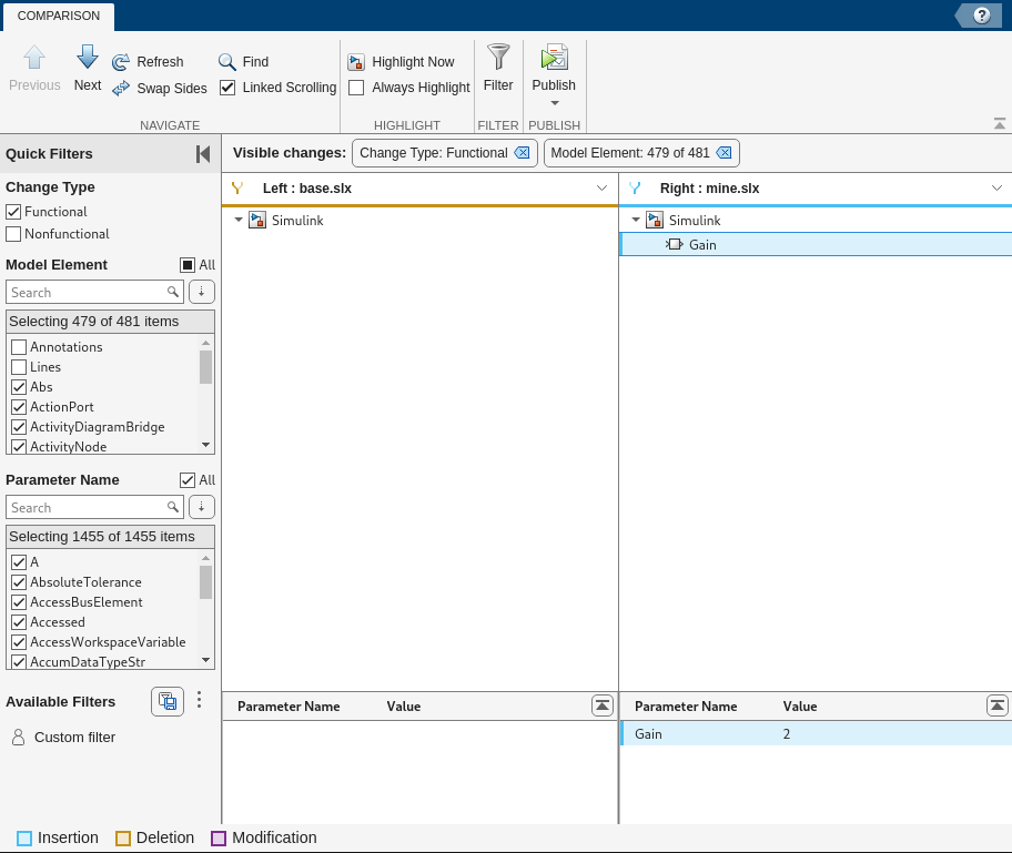
Comparison report with a toolstrip on top, Quick Filters pane on the left, and a side-by-side comparison on the right

 Functionality being removed or changed

Legacy command-line SVN integration is no longer supported

Legacy command-line SVN integration had limited functionality and required installation of an additional command-line SVN client. Starting in R2024b, the command-line SVN integration is no longer supported. Use the built-in SVN integration instead.

This illustration shows the deprecated Command-line SVN integration (compatibility mode) option in the Manage Files Using Source Control dialog box. Use the SVN (1.9) option instead.
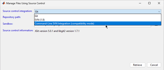
Data Management

Manage model design data using MAT Files

Prior to R2024b, you could manage design data associated with Simulink models by using the base workspace or a Simulink data dictionary as an external data source. The design data determines the behavior of the model and can include variables and data objects that specify block parameters and signal characteristics. You use the base workspace to create variables while you experiment with temporary models. You use a data dictionary to permanently store data that can be shared among multiple models, and attach to those models for easy reuse.

Starting in R2024b, you have the option to store and use design data using the MAT files (.mat) as an additional external data source. This feature enables you to manage model-related design data using a MAT file as an external data source that can permanently store data, which you can attach to your model for subsequent use. This eliminates the need to import MAT file data into the base workspace or into a data dictionary. Additionally, it synchronizes any changes made in the design data from Simulink with the MAT file.

To add an external MAT file source, in the Simulink Toolstrip, on the Modeling tab, click Model Explorer and navigate to the External Data tab. Under Additional data sources, select the MAT files to add to the model.

Alternatively, you can also manage the external data sources programmatically by using these functions:

PurposeFunction
Add an external data source to the model.Simulink.data.dataSource.addSource
Detach the data source from the model.Simulink.data.dataSource.removeSource
Check if the specified data source is attached to the model.Simulink.data.dataSource.hasSource
Fetch the complete list of data sources attached to the model.Simulink.data.dataSource.getSourceNames

You can also use MAT files with subsystem reference. For more information, see Manage subsystem reference data using MAT files.
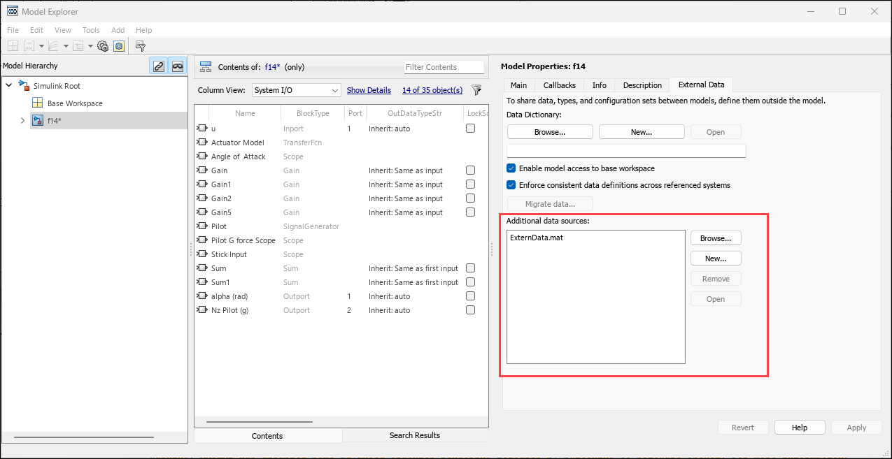
External data tab opened in model explorer window.

Signal Editor tool updates

The Signal Editor tool has these updates:

  • Set up and preserve the display format for the scenario data table that contains the TIME and DATA columns using the Display Format parameter. The Signal Editor tool remembers up to five signal data settings. The Display Format parameter sets the display format for time and for floating-point and fixed-point data. For more information, see Change Signal Data Output Format Preferences.

  • To programmatically open the Signal Editor tool with the active scenario signals already plotted, use the new signalEditor function InitialScenario argument with an existing scenario. For more information, see Signal Editor

  • When you click Browse in the Export dialog box, the Save as type parameter now provides a list of supported file extensions to which to export the file.

  • When you start the Signal Editor interface separately from the block, you can now provide the model parameter to access variables from the MAT file attached to the model. Prior to R2024b, you could provide the model parameter to access variables from only the model workspace or data dictionary.

Custom input mapping for package functions supports +packageName/fcnName format

For custom input mappings, package functions must have the input format +packageName/fcnName. Do not use the format packageName.fcnName. For more information, see Attaching Input Data to External Inputs via Custom Input Mappings.

Root Inport Mapper tool updates

The Root Inport Mapper tool has these updates:

  • Import signals from a custom registered file type using the new From Custom File menu in the toolstrip. For more information on custom registered file types, see Create Custom File Type for Import.

  • Use these functions to access custom registered file types for the Root Inport Mapper tool:

    • getSupportedFileTypes — Return registered file types that support the creation of a reader and retrieve metadata from input files.

    • mapDataToInport — Return mapping results of input file to the specified model.

    • loadScenarioToWorkspace — Assign a variable on files such as .mat, .xls, .xlsx, and custom file types to the base workspace.

signalBuilderToSignalEditor function renames block

The signalBuilderToSignalEditor now lets you rename the resulting Signal Editor block to Signal Editor. Prior to R2024b, the block was not renamed.

Simulink.LookupTable objects support tuning of sizes of tables and breakpoints during simulation

Simulink.LookupTable objects now support tuning of sizes of tables and breakpoints during simulation between successive runs. To enable this, in the Advanced tab, select the Support tunable size property and click Apply. Prior to R2024b, only code generation was supported for the Support tunable size property.

Simulink.Breakpoint objects support tuning of sizes of tables and breakpoints during simulation

Simulink.Breakpoint objects now support tuning of sizes of tables and breakpoints during simulation between successive runs. To enable this, in the Advanced tab, select the Support tunable size property and click Apply. Prior to R2024b, only code generation was supported for the Support tunable size property.

Manage subsystem reference data using MAT files

Previously, subsystem reference supported only data dictionaries as external data sources to manage model-related data. Starting in R2024b, you can also link MAT files to a subsystem file to store model-related data for easy reuse in child blocks and instances of the subsystem file. The scope of data you define in the MAT file is within the boundary of the Subsystem Reference block.

When you link a MAT file to a subsystem reference, the symbol resolution for any child block of the subsystem reference follows this order:

  1. Mask workspaces of all blocks, starting from the child block and moving upward to the mask workspace of the Subsystem Reference block.

  2. The data dictionary and MAT files linked to the subsystem file.

To link a MAT file to a subsystem reference, see Link a MAT File to a Subsystem File. You can also manage MAT files programmatically. For more information on these functions, see Manage model design data using MAT Files.

Code generation and simulation support for fixed-point data types greater than 128 bits

You can now simulate and generate code for Simulink models using fixed-point data types with word lengths up to 65,535 bits. Prior to R2024b, the maximum word length was 128 bits.

The new maximum word length is equal to that of the fi (Fixed-Point Designer) object. For more information, see Supported Data Types (Fixed-Point Designer).

Parameter Quantization Advisor: Access precision loss diagnostic parameters using toolstrip options

The Parameter Quantization Advisor app now includes options for adjusting parameter precision loss diagnostic configuration parameters in the Precision Loss section of the toolstrip. Update and apply the new settings to the model to see the impact on the diagnostics reported in the app.

View the current state of diagnostic parameter settings in the Model Configuration Parameters panel of the Parameter Quantization Advisor app.
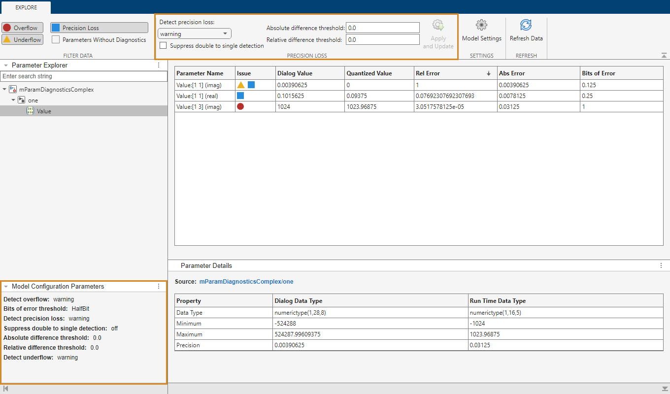
Screenshot of the Parameter Quantization Advisor app. The new Precision Loss toolstrip section and the new Model Configuration Parameters panel are highlighted.

 Functionality being removed or changed

Configuration sets no longer included in data dictionary exported to earlier release

Behavior change

If you export a data dictionary containing configuration sets to an earlier release, the configuration sets are no longer included and the software issues a warning. Previously, the software issued a warning that these configuration sets might be reset to default values.

To work around this, attach the configuration set to a temporary model. Then export the model to the earlier release and copy the attached configuration set to the data dictionary. See Manage Configuration Sets for a Model for more information.

Block Enhancements

Reuse mask parameters and dialog controls across multiple masked blocks

Starting in R2024b, use a mask part reference container to save parameters and dialog controls in an XML file to refer to and reuse them across multiple masked blocks. See Reuse Mask Parameters and Dialog Controls Across Multiple Masked Blocks for more information.

Load int64 and uint64 data using the From Workspace block

The From Workspace block now supports loading input signal data values that have an int64 or uint64 data type. When you use the From Workspace block to load int64 or uint64 signal data:

  • Only the signal values can have the int64 or uint64 data type. Time values must have double data type.

  • Use a format other than array, such as timetable, timeseries, or structure. Array format does not support any data type other than double.

While loading int64 and uint64 signal data is supported in all simulation modes, interpolation of int64 and uint64 data is not supported in rapid accelerator simulations.

Signal Editor block updates

The Signal Editor block has these updates:

  • When you open the Signal Editor tool from the Signal Editor block, the Signal Editor tool now opens with all the active scenario signals already plotted.

  • The Signal Editor block supports loading input signal data values that have an int64 or uint64 data type. When you use the Signal Editor block to load int64 or uint64 signal data:

    • Only the signal values can have the int64 or uint64 data type. Time values must have double data type.

    • Use a format other than array, such as timetable, timeseries, or structure. Array format does not support any data type other than double.

    While loading int64 and uint64 signal data is supported in all simulation modes, interpolation of int64 and uint64 data is not supported in rapid accelerator simulations. To load int64 or uint64 data into a rapid accelerator simulation:

    1. Clear the Interpolate data parameter.

    2. Set the Form output after final data value by parameter to any value except Extrapolation.

Expand Scalar block supports struct expansion

The Expand Scalar block now supports MATLAB struct expansion with the Simulink bus data type.

Complex to Magnitude-Angle block supports fixed-point inputs

Complex to Magnitude-Angle block now supports the CORDIC approximation method. This method allows fixed-point inputs at input Port_1. To select the CORDIC method, set the new Approximation method parameter to CORDIC.

When you select the CORDIC method, the block icon updates.

Complex to Magnitude-Angle block icon with CORDIC approximation method input

1-D Lookup Table, 2-D Lookup Table, and n-D Lookup Table block updates

The 1-D Lookup Table, 2-D Lookup Table, and n-D Lookup Table blocks have these updates:

  • Tune the size of the lookup table and breakpoint data during simulation between successive runs or in the generated code without regenerating or recompiling the code. Use the Support tunable size parameter. Selecting the Support tunable size parameter enables Tunable Size fields for the Breakpoints parameters. Enter the new tunable size values in these fields.

    For the block icon, table of output variables T changes to T*.

  • For the 2-D Lookup Table block only, for better accuracy without performance overhead when possible, use the Apply more accurate and efficient rounding when possible parameter. To enable this parameter:

    • Set Interpolation method to Linear point-slope.

    • Set Extrapolation method to Clip.

To String block generates more efficient code

The To String block now generates more efficient code for enumerations by generating a shared function for each enumeration type. Prior to R2024b, this block generated inlined code for enumerations.

Use customizable Check Box block to set parameter value by checking or clearing check box

Starting in R2024b, you can model check boxes in digital user interfaces using the Check Box block from the Customizable Blocks library. To change the value of a parameter using the Check Box block, connect the block to the parameter, and then check or clear the check box. For information about how to connect dashboard blocks, see Connect Dashboard Blocks to Simulink Model. By default, checking the check box sets the parameter value to 1. Clearing the check box sets the value to 0. To customize these values, open the Parameters tab of the Property Inspector and change the Cleared value and the Checked value.

To check or clear the check box during simulation, click the check box icon on the Check Box block. To check or clear the check box when the simulation is not running, click the Check Box block, then click the check box icon.

You can customize the appearance of the block using the Design tab in the Property Inspector.

  • Change the icon that represents a checked check box.

  • Change the icon that represents a cleared check box.

  • Change the text and the font color of the label.

  • Change the position of the icons and label within the block.

  • Add a background image to the block, or choose a background color.

  • Add a foreground image to the block.

Customizable Check Box block

Unlock dashboard block aspect ratio with keyboard

If the aspect ratio of a block from the Dashboard library is locked, you can now temporarily unlock the aspect ratio by pressing Shift. When you release the Shift key, the aspect ratio locks.

If the aspect ratio is unlocked, pressing Shift temporarily locks the aspect ratio. When you release the Shift key, the aspect ratio unlocks.

New View Filter Response button in Discrete Filter, Discrete FIR Filter, and Discrete Transfer Fcn blocks

Starting in R2024b, you can click the new View Filter Response button to visualize the frequency response of the filters in these blocks:

This button appears in the block dialog box only if you have a valid DSP System Toolbox license.

C Caller block: Support for Simulink strings

Starting in R2024b, you can specify Simulink strings for C Caller block ports associated with C strings such as character pointer (char*) and character array (char[]) specified in your custom code.

C Caller block: Use command line APIs to add or delete global variables as inputs or outputs

Starting in R2024b, you can use command line APIs, addGlobalArg or deleteGlobalArg to manually add or delete global variables as function interfaces, respectively.

Group data by source in the Playback block

Starting in R2024b, you can group signals in the Playback block by source in addition to the existing options of grouping by data hierarchy or displaying a flat list of signals.

When you group signals by source, signals are organized based on the origin of the data:

  • File — Signals sourced and referenced from a file are collected in a group specified by the filename. If you add signals from multiple files, a group is created for each file.

  • Workspace — Signals sourced and referenced from the workspace are collected in a group named Workspace.

  • Saved in model — Signals that are saved to the model, such as signals sourced from the Simulation Data Inspector, are collected in a group named Signals saved in model.
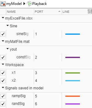
Signals grouped by source in the Simulation Data Inspector.

Propagate element names from In Bus Element blocks

You can now propagate element names from In Bus Element blocks as signal labels. For example, for an In Bus Element block labeled InBus.nonconstant.chirp, the propagated signal label is chirp.

For more information, see Signal Label Propagation.

Specify initial conditions for Out Bus Element blocks

In conditionally executed subsystems and models, Out Bus Element blocks now support initial conditions on the top-level element. For nonbus signals, set Initial output to a value with the same dimensions and complexity as the signal. For buses, set Initial output to a MATLAB structure with fields that have the same names and hierarchy as the elements of the bus. To specify what happens to the block output when the subsystem is disabled, use the Output when disabled block parameter.

For more information, see Out Bus Element.

Specify Bus Selector block parameters in Property Inspector

You can now specify Bus Selector block parameters in the Property Inspector. When you make changes in the Property Inspector or Block Parameters dialog box, the changes apply immediately. The Apply and OK buttons have been removed.

The Bus Selector block must have at least one output element. To completely replace the output elements, add elements from the input bus to the block output. Then, remove the original output elements. For example, for a new Bus Selector block, add elements from the input bus to the block output. Then, right-click the placeholder element named signal1 and select Remove all invalid elements.

When you find the source blocks of input elements, the source blocks are now selected instead of highlighted. The Property Inspector shows the parameters of the selected source block. When you select the source block of multiple elements, the Property Inspector shows the parameters of the source block that has focus. To reflect this change, the Highlight source blocks option () is now called Select source blocks.

Bus Selector block parameters in Property Inspector

Rename mask callback file

Starting in R2024b, you can rename a mask callback file.

Create and associate Simulink.Parameter variable to a mask popup parameter

Starting in R2024b, you can create and associate both Simulink.Parameter and MATLAB variables to mask popup parameters directly from the mask dialog box.

Click the three-dot button (...) to the right of the popup parameter in the mask dialog box to create and associate the variable.
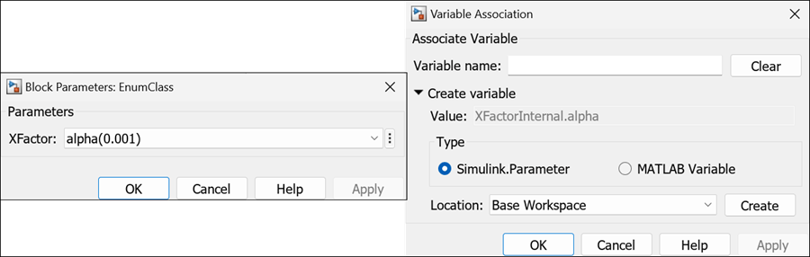
Block parameter dialog box and Variable Association dialog box.

See Tune Mask Enumeration Parameters - Popup and Radio Button for more information.

Use standalone constraint manager to manage constraint file

Starting in R2024b, you can launch a standalone constraint manager by using the Simulink.ConstraintManager.open function. The standalone constraint manager enables you to manage multiple shared constraint files without a block context. See Author Parameter and Port Constraints Using Standalone Constraint Manager for more information.

Preserve tunability of mask parameters in generated code for enumeration and mustBeMember properties of System object

Starting in R2024b, when you reference a System object in a MATLAB System block, the conversion of enumeration and mustBeMember system object properties to mask parameters have these improvements:

  • Simulink converts system object properties of type Simulink.IntEnumType and Simulink.Mask.EnumerationBase to a mask popup parameter with type options referencing an enumeration file. This preserves simulation and code generation tunability of such properties. Previously, the properties were converted to a popup parameter that was not tunable.

  • Simulink converts a system object mustBeMember property with supported values as character vector to a nontunable mask popup parameter. The type options are set to the mustBeMember values, which identifies the list of supported values.

Use options to associate plain strings to type options of popup and radio button parameters

Mask editor type option dialog box now distinguishes the way you specify options for popup and radio button parameters.

In the Mask Editor Type options menu, use Options to associate plain strings to parameter options. Use Options with custom values to associate specific values to options. See Tune Mask Enumeration Parameters - Popup and Radio Button for more information.

Graphical Icon Editor: Customize the shape of a block icon

Starting in R2024b, you can customize the shape of a block icon using custom shapes. Select a shape from the Frame list in the Icon Properties pane of the Graphical Icon Editor.
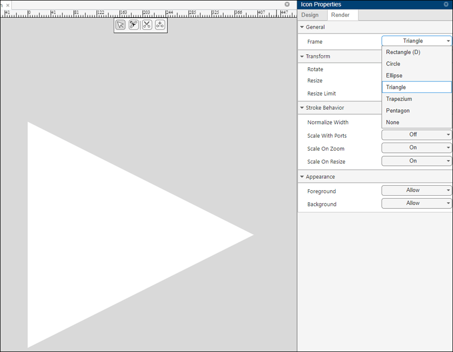
Graphical Icon Editor. In the Icon Properties pane, the value Triangle is selected from the Frame list. In the canvas, the icon is in the shape of a triangle.

Graphical Icon Editor: Use an interactive interface to define visibility conditions

Starting in R2024b, you can build visibility conditions of mask icon elements through an interactive user interface. See Set Visibility Condition Based on Evaluated Value of Parameters for more information

Graphical Icon Editor: View the properties and configurations of masked Simulink library block icons in read-only mode

Previously when you open masked Simulink library blocks in read-only mode, you could only preview the block icon and all other actions were disabled. Starting in R2024b, you can navigate to each element of the icon. You can also view the element properties in properties panel and toolstrip widgets.

Import co-simulation FMU that contains time-based clocks

You can now use the FMU block to import a co-simulation Functional Mockup Unit (FMU) that contains time-based clocks as defined in the FMI 3.0 standards. Simulink registers the time-based FMU clock variables as sample times of the FMU block, enabling it to handle the clock event updates and synchronize with the FMU.

To enable simulation with clock events, on the FMU block dialog, in the Co-simulation settings of the Simulation tab, select the Enable event mode check box and set Communication step size parameter as -1. You can compile the model to see the registered sample times.

For an example of importing time-based clock to Simulink, see Import and Simulate FMU with Time-Based Clocks in Simulink.

Note

You can use FMU with clocks only for normal mode simulation.
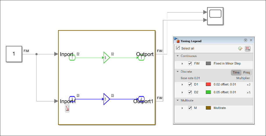
FMU with sample times

Specify Simulink test artifacts as block test in Blockset Designer

You can now specify test suites, created using Simulink Test Manager or using MATLAB-based Simulink test case class sltest.TestCase (Simulink Test), as block tests in Blockset Designer.

In Blockset Designer, use the Create button in the test section to create a test harness for your model. In the Test Suite field, specify the path to the test file (.mldatx) created using Simulink Test Manager or specify the path to MATLAB-based Simulink test file (.m) that is a derived class from sltest.TestCase. You can also specify an existing test harness model and its associated test artifacts.
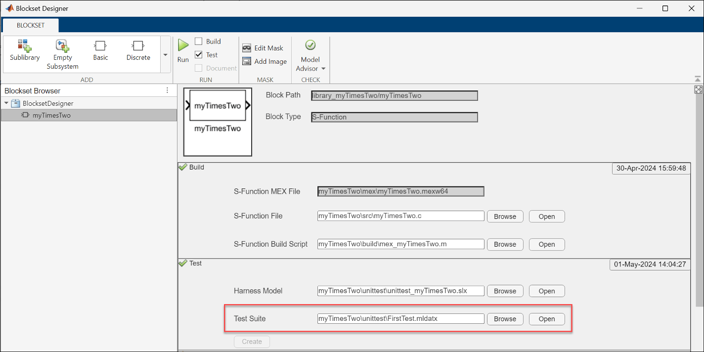
Blockset Designer block page with mldatx test suite

PID Controller Blocks: Specify anti-windup algorithm externally using new ports

The PID controller blocks now allow you to specify an anti-windup algorithm externally using a new input port extAW. The block also provides the signal before the integrator at the preInt output port that you can use as input for the custom algorithm. The PID controller blocks provide two built-in anti-windup methods, however, to unwind the integrator, these methods rely on the sum of the block components exceeding the specified block output limits. If your application has saturations or limits downstream of the PID controller blocks, you can use the new extAW and preInt ports to implement a custom anti-windup logic. To enable the new ports, on the Saturation tab, select Limit Output and set Anti-windup Method to external.

 Functionality being removed or changed

Support tunable table size in code generation and Maximum indices for each dimension parameters replaced with Support tunable size

In lookup table blocks, the Algorithm > Support tunable table size in code generation parameter has been replaced with the Table and Breakpoints > Support tunable size parameter. Due to this change:

  • If you set the Table and Breakpoints > Support tunable size parameter programmatically with SupportTunableTableSize, the next time you open the lookup table block, the block displays a warning. Existing models continue to work.

  • The Support tunable size parameter on the Table and Breakpoints tab replaces the Support tunable table size in code generation and Maximum indices for each dimension parameters on the Algorithm tab. Prior to R2024b, selecting the Support tunable table size in code generation parameter enabled the Maximum indices for each dimension, which set the maximum index value for each table dimension. Starting in R2024b, selecting the Support tunable size parameter enables Tunable Size fields for the Breakpoints parameters. These Tunable Size fields replace the functionality of the Maximum indices for each dimension parameter. The blocks display a warning on the block dialog box. Existing models continue to work. For more information, see Tunable size.

String to ASCII block output dimension change

Behavior change

The String to ASCII block output dimension has changed from a 2D row vector, such as a 2-by-N vector, to a 1D vector, N. N is the number of elements.

Connection to Hardware

Arduino Hardware: Use Simulink Support Package for Arduino Hardware in Simulink Online

Starting in R2024b, you can use Simulink Support Package for Arduino Hardware in Simulink Online to create, run, and deploy Simulink models on your Arduino hardware through your web browser. This requires that you install the MATLAB Connector™ on your host computer. For more information, see Get Started with Simulink Online for Arduino and Install MATLAB Connector for Hardware Connectivity.

Arduino Hardware: Support for Arduino Nano RP2040 Connect, Raspberry Pi Pico, and Raspberry Pi Pico W hardware boards

You can now deploy Simulink model containing the following blocks from Simulink Support Package for Arduino Hardware to the Arduino Nano RP2040 Connect, Raspberry Pi Pico, and Raspberry Pi Pico W boards. You can select the boards in the Hardware board drop-down in the Configuration Parameters dialog box.

The Raspberry Pi Pico and Pico W boards are compatible with Arduino. These boards are built around the RP2040 microcontroller designed by Raspberry Pi. You can set up these boards using the instructions in the Hardware Setup window. The setup procedure is similar to the other boards compatible with Arduino such as ESP32 and Teensy. For more information, see Supported Arduino Hardware.

Arduino Hardware: Support for on-board CAN

This release introduces the On-board CAN Receive and On-board CAN Transmit blocks for the Arduino Due and Teensy 4.0 and 4.1 (Arduino Compatible) hardware boards. You can use these blocks to send and receive messages over a controller area network (CAN). For more information on configuring on-board CAN properties, see On-board CAN properties.

Arduino Hardware: Connected IO support for blocks

You can now deploy a Simulink model to an Arduino board in the connected IO mode when the model contains the following blocks.

For more information on how to use connected IO, see Communicate with Hardware Using Connected IO.

Arduino Hardware: Support added for Servo and PWM on Teensy 4.0 and 4.1 hardware boards

Simulink Support Package for Arduino Hardware now includes the following features for the Teensy 4.0 and 4.1 that are compatible with Arduino:

  • Deploy a Simulink model containing Continuous Servo Write, Standard Servo Read, or Standard Servo Write blocks on the Teensy hardware boards.

  • Specify an operating frequency for a PWM signal in the PWM block by using the Specify option under the Frequency drop-down. In the earlier releases, you could use only the Default option under the Frequency drop-down.

For more information, see Supported Default PWM Frequencies and Pins on Arduino Compatible Teensy Boards.

Arduino Hardware: Support added for Apple silicon Mac hardware

Starting R2024b, you can use the Simulink Support Package for Arduino Hardware to build and deploy Arduino applications on Apple silicon Mac computers.

Raspberry Pi Hardware: Support for Raspberry Pi 5 hardware board

You can now use Raspberry Pi Blockset to deploy Simulink blocks and models to the Raspberry Pi 5 hardware board. For more information, see Supported ARM Cortex -A Processors for Raspberry Pi Hardware.

Raspberry Pi Hardware: Support for Raspberry Pi Debian Bookworm OS

You can now use Raspberry Pi Blockset to generate code for 32-bit and 64-bit Raspberry Pi Debian Bookworm operating systems. For more information, see Install Support for Raspberry Pi Hardware.

Raspberry Pi Hardware: Support added for CMSIS CRL

Raspberry Pi Blockset now includes the code replacement library (CRL) ARM Cortex-A CMSIS to generate calls to the CMSIS-DSP library optimized for ARM® Cortex®–A processors. To use this feature, you must have an Embedded Coder license. For more information, see Optimize Code for Raspberry Pi Using Code Replacement Library.

Raspberry Pi Hardware: Receive video using RTSP Video Stream Receive block

This release introduces the RTSP Video Stream Receive block, which you can use to receive a video from a streaming source using the real-time streaming protocol (RTSP). You can create a source to stream the video over a network using either the RTSP Video Stream Transmit block or any other RTSP streaming device. The block can decode the video stream using the H264 or JPEG video encoding standards. For more information, see Receive Video Over Network Using Raspberry Pi Video Stream Receive Block.

Raspberry Pi Hardware: Read temperature using TMP102 sensor

You can now interface the TMP102 digital temperature sensor with Raspberry Pi hardware using Raspberry Pi Blockset. You can use the TMP102 Temperature Sensor block to measure ambient temperature.

MATLAB Function Blocks

Use class properties to define name-value arguments in MATLAB Function block

In MATLAB, you can use the public properties of a class to define name-value arguments in an arguments block by using the syntax structName.?ClassName. See Name-Value Arguments from Class Properties.

Starting in R2024b, you can generate C/C++ code for non-entry-point MATLAB functions that use this syntax in an arguments block. Name-value arguments, including the structName.?ClassName syntax, are not supported in entry-point functions. See Generate Code for arguments Block That Validates Input and Output Arguments.

Perform simulation and code generation that depends on fewer platform-specific precompiled libraries

Starting in R2024b, when performing simulation or code generation using MATLAB Function blocks, you can instruct the code generator to avoid using platform-specific precompiled libraries when possible. To perform this action, set the model configuration parameter Use precompiled libraries for MATLAB functions to Avoid precompiled libraries when possible. The code generator uses precompiled libraries only if no alternative implementations of their algorithms are available.

By default, during simulation or C/C++ code generation, the code generator prefers to use the available precompiled libraries because these libraries are optimized for performance on specific platforms. However, because precompiled libraries are platform specific, their use restricts the portability of the generated code. Avoiding calls to these libraries and generating portable implementations of their algorithms produces applications that can run on many platforms.

For GPU acceleration or code generation, the Use precompiled libraries for MATLAB functions parameter has a different default, compared to normal simulation or C/C++ code generation. During GPU acceleration or code generation, the default behavior of the code generator is to avoid using precompiled libraries when possible. To change this behavior, set the parameter manually.

For certain precompiled libraries (for example, BLAS, LAPACK, and FFTW), there exist individual configuration parameters that allow you to customize their usage. The Use precompiled libraries for MATLAB functions parameter does not affect the use of these libraries.

Use dictionaries in MATLAB Function block

In R2024b, you can generate C/C++ code for MATLAB functions that use dictionary objects.

Code generation supports most data types for the keys and values in dictionaries, including:

  • Aggregate data types, such as structures and cells

  • Numeric, logical, half, character, string, and enumeration types

  • Complex numbers

To learn more about code generation for dictionaries, see Generate Code for Dictionaries. To generate code for MATLAB functions that use dictionaries, you must adhere to certain restrictions. See Dictionary Limitations for Code Generation.

Code generation for more toolbox functions

In R2024b, you can generate code for many additional toolbox functions and objects. For a list of all functions and objects that are supported for code generation, see:

These are links to the release notes of some toolboxes that added code generation support in R2024b:

Image Processing Toolbox

See C Code Generation: Generate code from additional functions using MATLAB Coder (Image Processing Toolbox).

Signal Processing Toolbox

See C/C++ code generation support for descriptive statistics, signal modeling, vibration analysis, and waveform generation (Signal Processing Toolbox).

Wavelet Toolbox

See C/C++ Code Generation: Automatically generate code for 2-D continuous wavelet transform (Wavelet Toolbox).

R2024a

New Features, Bug Fixes, Compatibility Considerations

 Preserve signal line shape when moving and resizing blocks

In Simulink versions before R2024a, when you move or resize a block, all other blocks stay in place, and the signal lines connected to the block move to accommodate the change in block position or size.

As a result, the signal lines may bend, and the block may cover nearby blocks. You may need to clean up the diagram.
The image is titled "Moving a Subsystem Block Before R2024a". The left half of the image shows a Subsystem block that connects to five Inport and five Outport blocks with short, straight signal lines. The right half shows the same blocks after the Subsystem block is moved in the downwards direction. The port blocks are in the same place as before, but the signal lines each have two bends.

Starting in R2024a, when you move or resize a block with three or more ports, any straight signal lines connecting the block to nearby blocks with one or two ports do not change shape. Instead, the connected blocks move.

If straight signal lines connect the block to a chain of consecutive blocks with one or two ports that are close to each other, the signal lines in the chain do not change their shape. Instead, the blocks move.

The affected signal lines and blocks highlight in green. This new functionality does not affect signal lines with branches or Simscape connections.

To temporarily turn the functionality off, hold the space bar while you move or resize a block. When you release the space bar, the functionality turns back on.

To turn the functionality off across MATLAB sessions, in the Simulink Editor, on the Modeling tab, from Environment, clear Preserve Alignment. To turn the functionality back on, select Preserve Alignment.
Short, straight signal lines connect a Subsystem block to five Inport blocks and five Outport blocks. The pointer moves the Subsystem block down and to the right. The port blocks and signal lines move with the Subsystem block. The signal lines stay straight. The pointer then drags the upper left corner of the Subsystem block outwards. The Subsystem block expands. The ports move such that the signal lines stay straight.

Convert Goto and From blocks to signal lines

You can simplify your model diagrams by replacing lengthy signal lines with sets of connected Goto and From blocks. However, when you want to trace a signal path, seeing the signal lines can be useful.

You can convert signal lines and virtual buses to Goto and From block sets, and you can convert Goto and From block sets to signal lines. A Goto and From block set is a connected group of Goto and From blocks that have the same tag.

To convert a Goto block and all From blocks to which it connects or a From block and the Goto block to which it connects to a signal line, select the block. Pause on the ellipsis that appears above the selected block. In the action menu that expands, select Convert to signal.

In the video, there is a Sine Wave block connected to a Goto block, and a From block connected to a Scope block. The pointer selects the Goto block, and uses the action menu to convert the Goto and From blocks to a signal line that connects the Sine Wave block to the Scope block.

To convert a signal line or bus to a Goto and From block set, select the signal line or bus. Pause on the ellipsis that appears. In the action menu that expands, select Convert to Goto and From blocks.

For more information about converting between signal lines and blocks, see Convert Signal Lines to Goto and From Block Sets.

Search for and select blocks connected without signal lines using toolstrip button

Related blocks connect to each other without signal lines.

When you select one of a set of related blocks, you can now use the Related Blocks button in the Simulink Toolstrip to find and switch selection to a different block in the set. For example, if you select a Goto block, you can switch the selection to a From block with the same tag. The button both switches selection to the related block and automatically navigates you to the location of the related block.

To switch selection from related block to another, in the toolstrip, on the block-specific tab of the selected block (for example, the Goto tab for a Goto block), in the Navigate section, click Related Blocks.

If the selected block only has one related block, the selection switches to the related block. If the selected block has more than one related block, a list of related blocks appears. Navigate to the name of the block you want to select by clicking or using the arrow keys on your keyboard, then press Enter.

For more information, see Search for Blocks Connected Without Signal Lines.
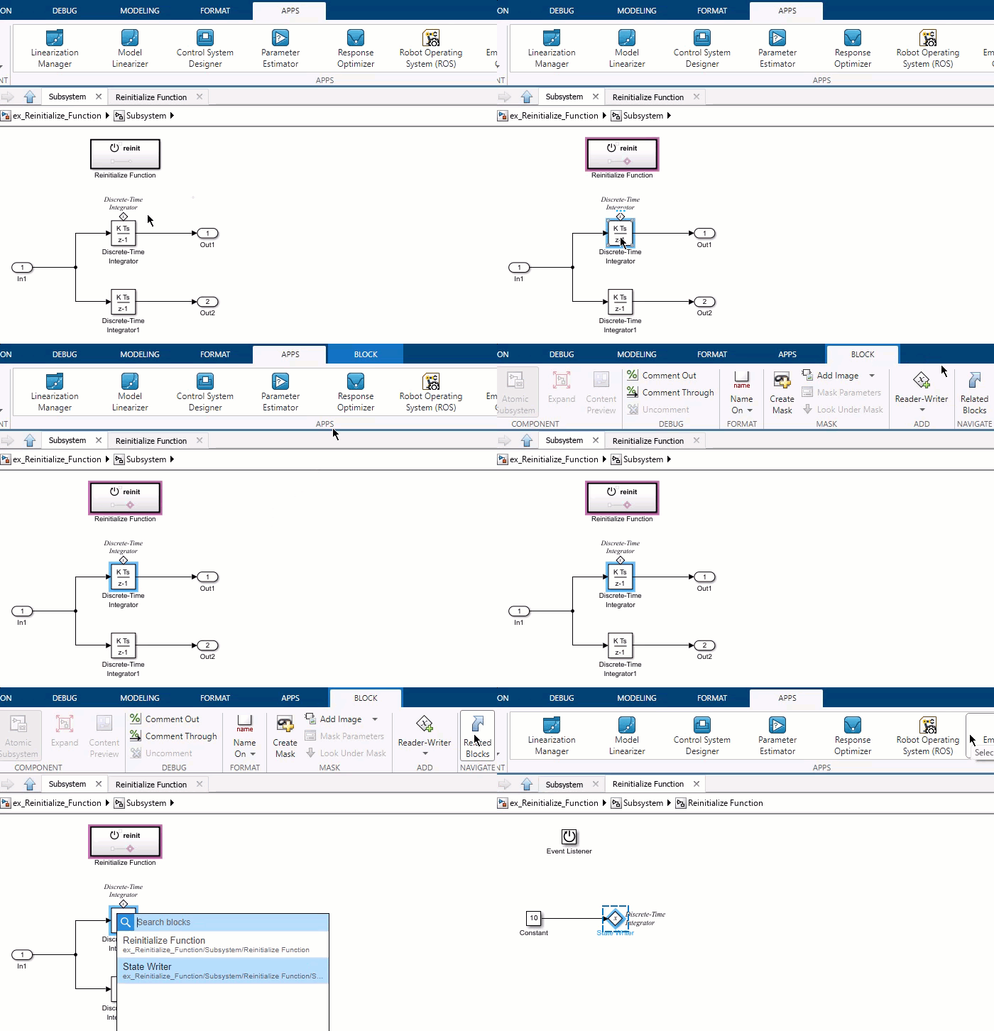
In the video, there is a subsystem named Initialize Function and a Model block named Model_1 that is a parameter owner block. The pointer selects the Model block. In the toolstrip, the Model Block tab appears. In the Model Block tab, the pointer clicks the Related Blocks button. A list of two related blocks appears: the Initialize Function, and the Parameter Writer. The pointer clicks the Parameter Writer. The Initialize Function subsystem opens, and the Parameter Writer block is selected.

Enhancements to Model Finder

Model Finder has these enhancements to enable you to search for phrases, customize the Model Finder user interface (UI), and manage databases with ease.

  • Model Finder now supports using quotation marks for searching phrases to get more targeted results.

  • Model Finder UI includes newly added sections and tabs with additional features:

    1. Layout — Customize the UI layout by using buttons to toggle the visibility of the Recent, Databases, Filters, and Information panes.

    2. View — Customize the search results layout using these options:

      • Models — Select this view to display the models that match your search query. In this view, the search results include both standalone models and models that are referenced by examples and projects. You can view the list of examples and projects that use a specific model in the Information pane.

      • Categorized — Select this view to display the examples and projects that match your search query. You can view the list of models used in a specific example or project in the Information pane.

    3. Databases — Select the databases from the available list of databases registered with Model Finder to set the search location.

    4. Copy Command — To copy the command that opens a specific search result, click Copy Command.

    5. Location — Display the path on your system that stores a previously opened search result using the Model Finder. To copy the path, click the copy icon .

    6. Recommended Licenses — Display the licenses recommended to simulate a model, example, or project. The icons Green tick and Warning symbol indicate whether you have the license.

    7. File References — Display the external files that are referenced in the search result.

    8. Database — Manage databases by navigating to the Database tab. Within the tab, you have the option to create, import, delete, and view the contents of a database.
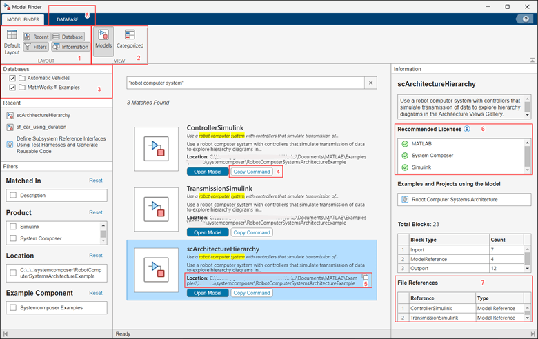
Model Finder UI

For more information, see Model Finder.

There are some changes in the functions used to configure database settings in Model Finder. For more information, see Model Finder function updates.

View block icons in the quick insert menu

Starting in R2024a, when you double-click the Simulink Editor canvas, the quick insert search results display block icons with the block names to enable you to easily identify the blocks.
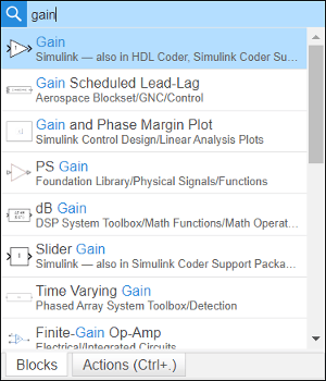
Quick insert search results displaying block icons and block names related to Gain search query.

 Functionality being removed or changed

Model Finder function updates

Errors

Model Finder functions have these changes:

Simulation Analysis and Performance

 Control simulation execution and tune parameter values in scripted simulations

The new Simulation object represents a simulation of a model and provides an interface to control the simulation execution and to tune parameter values during simulation. The Simulation object supports all simulation modes, including rapid accelerator, and deployment with Simulink Compiler. You can use the Simulation object to:

  • Configure, run, and interact with simulations.

  • Step forward through major time steps in simulation.

  • Write and deploy scripts that interact with simulations while they run.

  • Build and deploy apps that run and interact with simulations.

While you can programmatically interact with simulations you run using Simulation objects, you cannot interact with the model or simulation associated with a Simulation object using the Simulink Editor while the simulation has a status other than inactive.

For more information, see Run Simulations Programmatically.

 Interactively build custom apps with Simulink models using MATLAB App Designer

Interactively build a custom app that interfaces with a Simulink model using MATLAB App Designer. Use the App Designer design environment to:

  • Perform common simulation tasks from the app, such as starting and stopping the simulation and viewing simulation progress, using Simulink UI components.

  • Tune model variables from the app while the simulation runs by connecting UI components to variables.

  • Visualize simulation signals in the app by connecting signals to a time scope UI component.

To use Simulink UI components, in App Designer, drag the components from the Simulink section of the Component Library onto the canvas, or use these functions:

  • uisimdatabutton — Use simulation data buttons to load input data or save output data.

  • uisimcontrols — Use simulation controls to start, stop, pause, and continue a simulation.

  • uisimprogress — Use a simulation progress bar to view the simulation progress as it runs.

  • uisimvartuner — Use a variable tuner component to modify model variables from a table.

  • uitimescope — Use a time scope to visualize signal data in the app while the simulation runs.

For more information, see Create App for Simulink Model.

Debug simulation execution using the Execution Order viewer while stepping block by block

The debugging capability to step through execution block by block that was added in R2023a has improved integration with the Execution Order viewer.

  • Execution order highlighting no longer conflicts with the block-by-block debugging highlighting that indicates the block on which the simulation is paused.

  • The Execution Order viewer highlights the row in the execution list that corresponds to the block on which the simulation is paused, so you can track the position in the execution list alongside the location of the block in the model.

  • The Breakpoints List now has a button to open the Execution Order viewer.
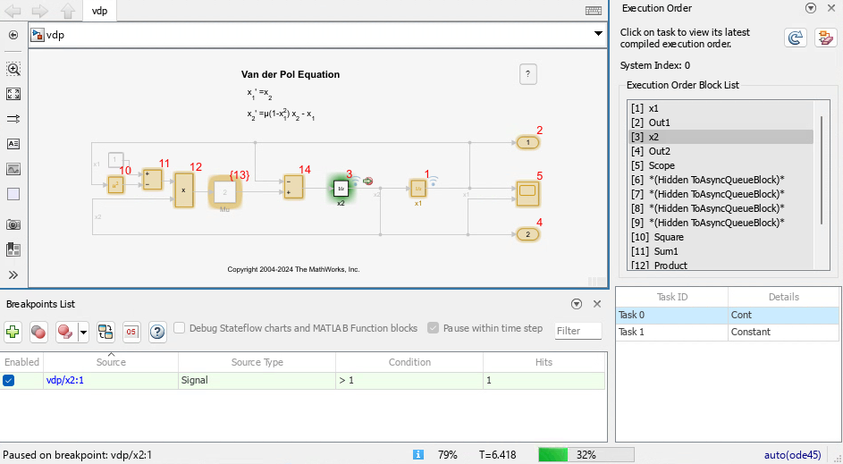
The Simulink Editor displays the block diagram for the model vdp and has the Execution Order viewer and the Breakpoints List open. A simulation debugging session is paused within a time step on the block named x2.

Increased flexibility for stepping block by block in simulation debugging session

When the Pause within time step option is selected in the Breakpoints List and a model contains at least one breakpoint before you start a simulation, you can use the Step Over button to step through the simulation block by block. Starting in R2024a, the Step Over button is available to start stepping block by block anytime such a simulation is paused, including when the simulation is paused between major time steps.

In R2023a and R2023b, the Step Over button was available only while paused within a time step. After the simulation paused within a time step, the Step Over became unavailable if you advanced the simulation through major time steps by using the Step Forward and Step Back buttons. You could not step block by block again until the simulation paused within a time step on a breakpoint.

For more information, see Debug Simulation Using Signal Breakpoints.

Improved support for stepping between Simulink block diagrams and Stateflow charts in simulation debugging sessions

Debugging simulations by stepping block by block in the Simulink Editor has enhanced support for stepping between Simulink block diagrams and Stateflow charts, including support for these situations:

  • Stepping into and out of a function-call subsystem that is controlled by a Stateflow chart

  • Stepping into and out of a Simulink function inside a Stateflow chart

  • Stepping into and out of a Simulink-based state inside a Stateflow chart

To enable stepping into Stateflow charts in a simulation debugging session, enable the Allow setting breakpoints during simulation configuration parameter before starting the simulation debugging session. For more information, see Breakpoints List.

sldebug prompt in MATLAB Command Window indicates when simulation debugging session is paused within time step

When you start a simulation debugging session using the Simulink Editor, you can issue some programmatic simulation debugging commands, such as probe or stop, while the simulation is paused within a time step. The sldebug command prompt (sldebug >>) now replaces the MATLAB command prompt (>>) to indicate in the MATLAB Command Window when the simulation is paused within a time step. As in prior releases, you can issue both MATLAB commands and the supported simulation debugging commands at the sldebug command prompt.

For more information, see Simulink Debugging Programmatic Interface.

View simulation time in Simulink Editor status bar during programmatic simulations

When you run a simulation using the sim function and the model is open, the status bar at the bottom of the Simulink Editor window for the model now updates to show the current simulation time for normal and accelerator mode simulations.
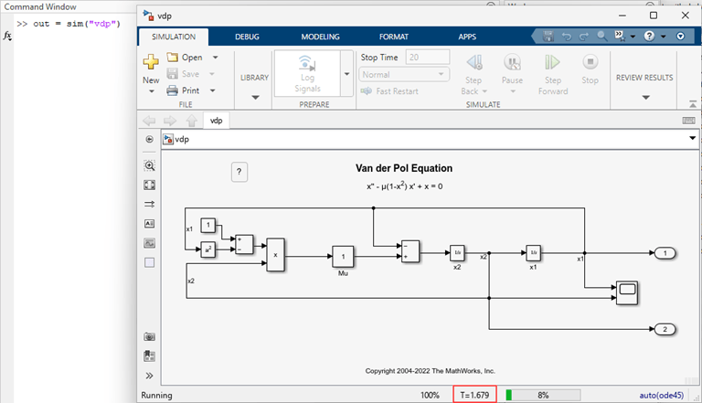
The MATLAB Command Window shows a call to the sim function to simulate the model vdp. The status bar in the Simulink Editor shows the simulation status, current simulation time, and the simulation progress. A red box added to the image indicates the location of the current simulation time in the status bar.

Run fast restart simulations using scalar Simulink.SimulationInput objects

You can now configure a Simulink.SimulationInput object to enable fast restart for an individual simulation you run using the sim function and a scalar SimulationInput object. Fast restart saves time in iterative simulation workflows by compiling the model only once, for the first simulation that has fast restart enabled. When you enable fast restart for an individual simulation using the sim function, at the end of the simulation, the FastRestart parameter remains enabled in the model and the model is initialized in fast restart.

You can also use the setModelParameter function to enable fast restart by setting the FastRestart parameter on a Simulation object.

The FastRestart parameter applies for only individual simulations you run one at a time. To use fast restart for multiple simulations you run together using an array of SimulationInput objects, use the UseFastRestart name-value argument.

For more information, see How Fast Restart Improves Iterative Simulations.

Profile execution of iterative simulations using Simulink Profiler and fast restart

Analyze the execution and performance of iterative simulations more quickly by using the Simulink Profiler with fast restart enabled. Fast restart saves time in iterative simulation workflows by compiling the model for the first simulation and then skipping the termination and compilation phases for subsequent simulations. To allow skipping the compilation phase, fast restart restricts the types of modifications you can make to the model. Fast restart is not supported for all models. For more information, see Get Started with Fast Restart.

Enabling and disabling the Simulink Profiler while initialized in fast restart is not supported. To use fast restart with the Simulink Profiler, enable fast restart, and then run a profiling simulation using the Simulink Profiler. After you finish profiling the simulation execution, disable fast restart to terminate the profiling simulation. Disabling fast restart also disables the profiler.

Increased default line width in visualizations

Starting in R2024a, the default line width for signals plotted in the Simulation Data Inspector, the Record block, the Playback block, and the Dashboard Scope block is 2 (px).

Improved support for importing MDF-files into the Simulation Data Inspector

The Simulation Data Inspector now offers improved performance and support for importing MDF-files.

  • Multidimensional data is now imported as a single signal with multidimensional sample values. After importing, you can choose to represent the data as a single signal with nonscalar sample values or expand the signal into a set of signals, called channels, with scalar sample values. Previously, multidimensional data was imported as channels that could not be collapsed into a single signal with multidimensional sample values.

  • You can now import string data.

  • Importing large MDF-files into the Simulation Data Inspector is now faster due to improved performance.

 Functionality being removed or changed

Code Analyzer warning for sim function syntaxes that return multiple output arguments

The Code Analyzer warns about calls to the sim function that return multiple output arguments. Since R2009b, the single simulation output syntaxes have been recommended, and multiple output syntaxes have been discouraged.

Support for syntaxes that return multiple output arguments will be removed in a future release.

Consistent error handling for sim function with scalar SimulationInput object

Behavior change

Starting in R2024a, the sim function has consistent default behavior and options for simulations you run using Simulink.SimulationInput objects. In prior releases, the sim function overwrote the CaptureErrors parameter for a single simulation if you specified one or more name-value arguments in addition to the scalar SimulationInput object, including the StopOnError name-value argument.

SimulationInput DimensionsCaptureErrorsStopOnErrorBehavior Change
scalar

"off" by default.

To enable this parameter, specify the parameter on the SimulationInput object using the setModelParameter function.

This name-value argument has no effect when you run a single simulation.

Some calls to the sim function in scripts or functions from previous releases might not return a Simulink.SimulationOutput object when the same calls had returned the simulation output in previous releases. To restore the prior behavior, specify the CaptureErrors parameter as "on".

vector, matrix, arrayAlways "on".

"off" by default.

Specify this name-value argument as "on" to skip subsequent simulations if a simulation error occurs.

No change.

slprofreport function has been removed

The slprofreport function and the ability to view profiling data generated prior to R2020a has been removed in R2024a. In R2020a, the Simulink Profiler was enhanced to capture profiling data as a Simulink.profiler.Data object to support programmatic analysis of the profiling results. Since R2020a, the slprofreport function has supported generating profiler reports only from profiler data generated prior to R2020a.

Executing size computation phase using model name requires input arguments

Behavior change

In previous releases, typing the name of the model with one or more output arguments and no input arguments executed the size computation phase of simulation. The table describes the behavior for using the model name as a programmatic interface without any input arguments starting in R2024a.

R2024a BehaviorCode Example

Typing the model name with one output argument returns the model handle.

h = MyModel;

Passing the model name to a function without single or double quotes is equivalent to passing the model handle to the function.

open_system(MyModel)

Typing the model name with multiple output arguments and no input arguments causes the software to issue an error.

[sys,x0,blks,st] = MyModel;
Too many output arguments.

To execute the size computation phase of simulation, you must specify input arguments.

[sys,x0,blks,st] = MyModel([],[],[],"sizes");

For more information, see Use Model Name as Programmatic Interface.

Using the model name as a programmatic interface to get a model handle is not recommended. Instead, after loading the model, use the get_param function to get the Handle parameter for the model. For example, this get_param command gets the handle for a model named MyModel.

h = get_param("MyModel","Handle");

Component-Based Modeling

 Use local solvers for components with faster dynamics

Local solvers for referenced models can now use a fixed step size that is smaller than the step size for the parent solver. Since R2022a, the software has required the local solver step size to be larger than the step size for the parent solver, limiting the use of local solvers to components with slower dynamics compared to the rest of the system. Starting in R2024a, you can use local solvers for components with dynamics that are faster or slower compared to the rest of the system.

Using a local solver can facilitate system composition and integration by:

  • Allowing system-level simulations to solve referenced models using the same solver and step size that were used to design and test each component in isolation.

  • Reducing the number of adjustments you need to make to configuration parameters of referenced models when integrating components into larger systems.

For some systems, using a local solver can improve simulation performance by allowing you to:

  • Choose a solver that is more appropriate to solve the system in the referenced model.

  • Choose different step sizes for one or more components instead of using a single step size for the entire system, which can reduce the number of redundant calculations in simulations of systems with a wide range of dynamics among components.

    For an example, see Improve Simulation Performance by Using Local Solvers.

For more information, see Use Local Solvers in Referenced Models.

Use local solvers for components that contain blocks that wrap state values

Starting in R2024a, you can configure a referenced model that contains a block with wrapped states to use a local solver. Wrapping states can improve numerical stability for systems with cyclical state values and allows the state value to wrap to the start of the cycle without resetting the solver, which can slow simulation performance.

For example, you can model the angular position of a wheel as having a value that is always between 0 and 2π. When the wheel rotates beyond an angular position of 2π, the angular position wraps back to 0 rather than continually increasing.

For more information, see Use Local Solvers in Referenced Models.

Variant Manager for Simulink: Enhanced variant configuration workflow for simulation and testing

Starting in R2024a, models that have variant configurations created using Variant Manager for Simulink have more streamlined simulation and testing workflows. You can now specify variant configurations as inputs to command line functions used to run single or multiple simulations, test cases, or test case iterations on the model. The specified variant configurations are applied before model simulation. This new workflow scales for models with a large number of variant control variables and provides traceability from the result object to the variant configuration used during simulation or testing.

Before R2024a, you had to either set the variant control variables that form a variant configuration as inputs to the command line functions, or activate the variant configuration by invoking the Simulink.VariantManager.activateModel function in callbacks before running the simulation or test.

New command line workflow for simulation and testing:

  • For simulation functions such as sim, parsim, and batchsim, you can set the VariantConfiguration property in the Simulink.SimulationInput object using the setVariantConfiguration function. For an example, see Run Simulations for Variant Models Using Variant Configurations.

  • In the Simulink Test programmatic interface, you can specify the variant configuration to use when running a test case. You can also run the same test case for different variant configurations in the model by creating test case iterations. To specify the configuration that must be activated for each iteration, set the VariantConfiguration property in the sltestiteration object. The TestCaseResult and TestIterationResult objects store the variant configuration used for each test case or iteration. The test specification report and test results report show these variant configurations as well. For an example, see Run Tests for Variant Models Using Variant Configurations.

Variant Manager for Simulink: View variant parameters grouped by bank

In the Variant Parameters tab in Variant Manager, use the Bank per row option to switch to a view in which parameters are grouped based on the variant parameter bank they belong to.
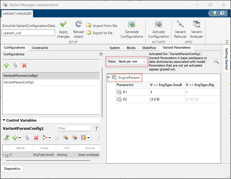
Variant Parameters tab in Variant Manager shows variant parameters grouped by bank using Bank per row option.

Variant Manager for Simulink: Support for Variant Start and Variant End blocks

Variant Start and Variant End blocks are now supported in Variant Manager tasks such as viewing and interacting with the blocks from the model hierarchy, importing control variables, understanding variable usage in a variant configuration, and activating a variant configuration.

Variant Manager for Simulink: Support for startup variant activation time in Variant Analyzer

The Variant Analyzer tool supports analyzing variant configurations for a model that contains variant blocks with startup variant activation time.

Variant Start and Variant End Blocks: Define conditions in a bounded region without creating a level of hierarchy

Starting in R2024a, use the Variant Start and Variant End blocks to limit variant condition propagation in a bounded region without introducing a level of hierarchy in the model. A bounded region is any region between the outport of a Variant Start block and the corresponding inport of the Variant End block without any intersection. You only need to specify the variant conditions and parameters on the Variant Start block.

Automated port synchronization in Variant Subsystem and Variant Assembly Subsystem blocks

When working with Variant Subsystem or Variant Assembly Subsystem blocks, the ports on the blocks match the ports in their underlying variant choices. In previous releases, you were required to manually analyze, copy, and paste the ports in these blocks to align them with the ports in variant choices, which was a time-consuming and error-prone process. Starting in R2024a, Simulink provides options to add missing ports and delete unused ports in Variant Subsystem and Variant Assembly Subsystem blocks to match the ports of the underlying variant choices. During simulation, if Simulink encounters a port mismatch between a Variant Subsystem or Variant Assembly Subsystem block and its variant choices, the resulting error message now provides these two options to resolve the issue:

  • Add missing ports — Adds missing ports to the Variant Subsystem or Variant Assembly Subsystem block, aligning them with the ports in the variant choices.

  • Add and delete ports — Adds missing ports and removes unused ports from the Variant Subsystem or Variant Assembly Subsystem block, aligning them with the ports in the variant choices. The deleted ports cannot be recovered, and any associated properties are lost.

Alternatively, you can use the Simulink.VariantUtils.updateVariantSubsystemPorts function to align the ports in a Variant Subsystem or Variant Assembly Subsystem block with the ports in its variant choices.

Use adapted rate-based model blocks as choices in a Variant Subsystem block

Starting in R2024a, you can use adapted rate-based model blocks as variant choices in a Variant Subsystem block. When you add adapted rate-based models as variant choices, the inports in the variant subsystem are matched to the port names of the respective rate-based models.

Define variant control variables of a Simulink Function block in the mask or model workspace

Starting in R2024a, you can define the variant control variables of a Simulink Function block with update diagram activation time in the mask or model workspace.

Access the mask of the active variant choice on Variant Subsystem block

Starting in R2024a, you can access the mask of the active variant choice of the Variant Subsystem directly without having to navigate inside the Variant Subsystem block with the following conditions:

  • If the Variant Subsystem block is unmasked, double-clicking on the block opens the mask of its active choice. Clicking on the Look under mask badge or selecting the corresponding option from the context menu of the Variant Subsystem block takes you directly inside the active choice.

  • If the Variant Subsystem block is masked and the active choice also has a mask, then the mask of the Variant Subsystem block gets the preference and double-clicking on the block will open the Variant Subsystem block mask.

Specify variant choices as an array of strings in Variant Assembly Subsystem block

Starting in R2024a, you can specify Variant choices specifier as an array of strings in Variant Assembly Subsystem block.

Propagate variant conditions to elements connected to the inport bus of the Bus Creator block in variant models with busses

Starting in R2024a, the variant conditions propagate to the elements connected to the inport bus of the Bus Creator block. Additionally, the generated code is optimized to execute based on the selected variant, eliminating any unnecessary code execution for inactive variants. Previously, in variant models that included buses, the elements connected to the inport bus of the Bus Creator block would always be active, regardless of the selected variant.

Specify custom header files without #include directive

Starting in R2024a, the Include headers parameter in Simulation Target and Code Generation tabs support a list of custom header files without #include directive. For more information, see Include headers.
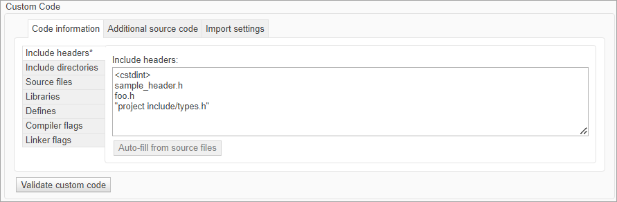
Include headers parameter of Simulation Target pane supports list of header files without #include directive.

Simulink Code Importer: Import C++ Class as reusable Simulink library

Starting in R2024a, you can use the Simulink Code Importer to import a C++ class to a Simulink Library from your custom C++ code library. For example, using the Simulink Code Importer you can import C++ class to a C Function block after analyzing the custom code for classes and their dependencies. For more information, see Import Custom C++ Class Using the Simulink Code Importer Wizard.

New example of modeling a Battery Management System

A new example shows how to design, model, and simulate a Battery Management System (BMS) for an NMC (Nickel-Manganese-Cobalt) cell with 3 Amp hr capacity. This example will include the best practices for collaboration, model composition and components, and interface and data management. For more information, see Use Model-Based Design To Build a Battery Management System.
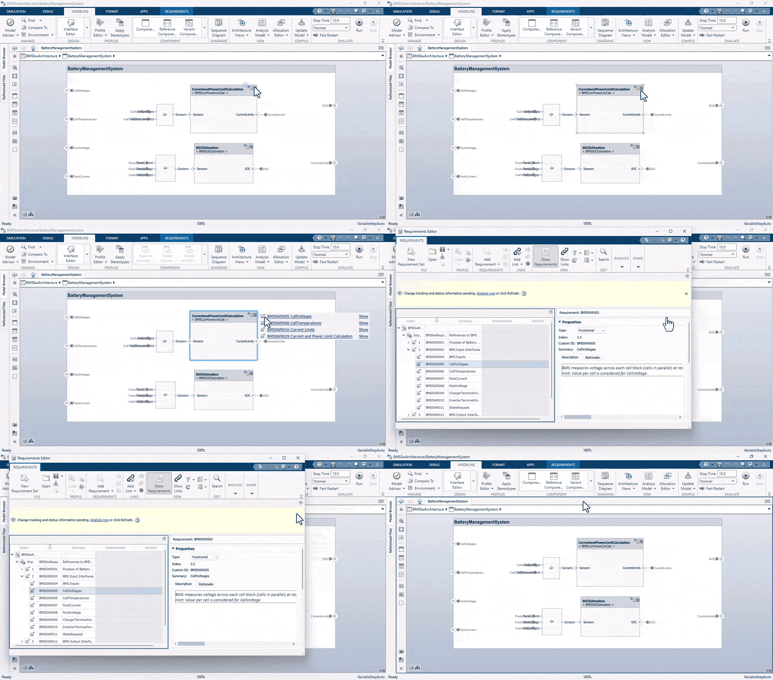
Convert model architecture to requirement

Convert logically executed Subsystem blocks to Subsystem Reference Blocks to reuse in models

You can now convert logically executed Subsystem blocks such as If Action Subsystem, Switch Case Action Subsystem, For Iterator Subsystem, and While Iterator Subsystem to Subsystem Reference and reference them in models to promote reusability and modularity. For information on converting Subsystem blocks to Subsystem Reference blocks, see Convert Subsystem to a Referenced Subsystem.

Optimized loading of models with Variant Assembly Subsystem blocks

Starting in R2024a, when you load a model with a Variant Assembly Subsystem block that has variant choices stored in subsystem files, only the active choice is loaded. This optimization shortens the loading time for such models.

Share port constraints with other masked blocks

Starting in R2024a, you can create shared port constraints enabling you to reuse them with other masked blocks. By saving the port constraints separately in an XML file, you can easily apply them to multiple masked blocks to achieve consistency and efficiency.

For more information on sharing a port constraint, see Share Port Constraints Across Multiple Masked Blocks.

Use constraints on literal edit parameters

You can associate constraints to literal edit parameters. If the Evaluate option in the Mask Editor is not selected, Simulink takes a literal reading of the input entry as you type it in the mask parameter dialog box. For example, you can store an IP address including the dots in a literal edit parameter. Simulink does not evaluate the parameter as if it were a mathematical expression. For more information, see Custom Constraint for Mask Parameter.

Optimized execution of mask parameter callback

Starting in R2024a, mask callback parameter does not execute if the parameter value remains unchanged. This improves the efficiency of mask callbacks by preventing unnecessary execution when the parameter value remains the same.

 Functionality being removed or changed

Extraneous discrete derivative signals diagnostic has been removed

Errors

The Extraneous discrete derivative signals (ModelReferenceExtraNoncontSigs) diagnostic configuration parameter has been removed.

When a discrete input to a Model block connects to the input of a block that has continuous states, the software resets the solver each time the discrete signal updates. The software does not issue a warning or error. Previously, the default behavior of this diagnostic was for the software to issue an error.

To diagnose solver resets, use the Solver Profiler instead. The Solver Profiler provides the number of resets and the reset sources. For more information, see Solver Resets.

Invalid root Inport/Outport block connection diagnostic has been removed

Errors

The Invalid root Inport/Outport block connection (ModelReferenceIOMsg) diagnostic configuration parameter has been removed.

When internal connections to the root-level port blocks of a model are invalid, the software silently inserts hidden blocks to satisfy the constraints wherever possible. This behavior matches the previous default behavior.

To diagnose and fix invalid connections, use Model Advisor check Check for invalid root input and output port connections (Simulink Check) (ID: mathworks.hism.hisl_0079) instead.

Reference tunable mask enumeration parameter by its name in child blocks to obtain the custom value associated with the option

Behavior change

If a mask enumeration parameter refers an external enumeration file or enumeration class for its options, you can now reference the parameter by its name in child blocks to obtain the custom value associated with the option during simulation and code generation.

Previously, child blocks had to reference tunable mask enumeration parameters using an internally created value array that contained the option values. The parameter name was referred to as valueArrayName(<parameterName>) to obtain the custom value for an option. For more information, see Tune Mask Enumeration Parameters - Popup and Radio Button.

lcc-win64 compiler not supported

Errors

The lcc-win64 compiler is no longer supported. For information about supported compilers, see Supported and Compatible Compilers - Windows.

Simulink.VariantControl object does not support Simulink.Parameter object with slexpr or nonscalar values

Behavior change

Starting in R2024a, the Simulink.VariantControl object does not support setting its Value property to a Simulink.Parameter object with Value set to the slexpr function or a nonscalar value.

Project and File Management

Project API: Find project files by label

You can now programmatically perform an advanced search in a project using the findFiles function. Supported workflows include:

  • Listing all files in a project

  • Filtering files that are not part of the project

  • Finding files by label or category name

  • Creating test suites from test files in a project and its references

Project API: Reanalyze all project dependencies

You can now programmatically reanalyze all files in your project and perform a complete dependency analysis by using the updateDependencies function.

Project API: Export list of project files to archive

You can now programmatically export a list of project files to an archive by using the export function.

For projects that have missing files, you can enable the export function to ignore the missing files.

Project Upgrade: Check for compatibility issues and upgrade project with improved usability and appearance

For projects that contain only MATLAB files, use Project Upgrade to check for compatibility issues with the current release. For projects that also contain Simulink models and libraries, you can apply fixes and automatically upgrade your project to the current release.

You can now easily interpret the upgrade results and examine the checks marked as need attention. You can also access frequent actions from the Project Upgrade toolstrip:

  • Rerun checks.

  • View changes that the upgrade applied.

  • Save results in a report.

For more information, see Check for Compatibility Issues and Upgrade Simulink Models Using Project Upgrade.
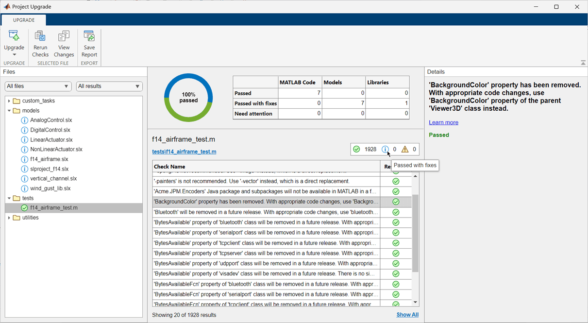
Project Upgrade tool with the toolstrip on top, list of files in the left pane, check details in the right pane, and results summary in the middle

Source Control: Support for signing Git commits

You can now enable the MATLAB Git integration to sign Git commits automatically. For more information, see Enable Signing Commits.

Source Control: Support for Git hooks

MATLAB Git integration can now run Git hooks with no additional setup. Starting in R2024a, you do not need to install Cygwin™ on Windows.

Supported hooks are pre-commit, commit-msg, post-commit, prepare-commit-msg, pre-push, pre-merge-commit, post-checkout, and post-merge. For more information, see Set Up Git Source Control.

Source Control API: Discard changes in Git repositories programmatically

You can now programmatically restore modified files in a Git repository using the discardChanges function.

Dependency Analysis API: Analyze Files in Toolbox and Files with Unsaved Changes

You can now programmatically include files inside of a toolbox and files with unsaved changes in your dependency analysis using the dependencies.fileDependencyAnalysis function.

Source Control in MATLAB Online: Expanded support for Git workflows

MATLAB Online now provides expanded support for Git workflows:

  • Squashing Git commits

  • Rebasing Git branches

Design Evolution Manager in MATLAB Online: Quickly browse, view, and switch between evolution trees

Use the Tree Browser pane to quickly browse, view, and switch between evolution trees in the current project and its referenced projects.
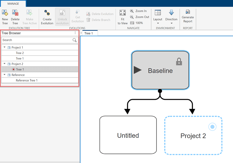
Screenshot of Design Evolution Manager app with Tree Browser pane highlighted.

Design Evolution Manager in MATLAB Online: Generate report of evolution tree

Click the Generate Report button to generate a PDF report that summarizes an evolution tree, including the evolution tree hierarchy and metadata.
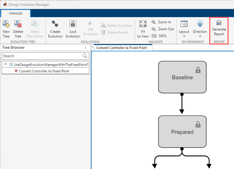
Screenshot of Design Evolution Manager app with Generate Report button highlighted in toolstrip.

polyspaceArtifact Function: Generate artifacts necessary for Polyspace analysis without regenerating code

In R2024a, you can generate Polyspace artifacts for a Simulink model without regenerating the code by calling the function polyspaceArtifact. You do not need to integrate Polyspace with Simulink to use this function. The function polyspaceArtifact is available with Simulink R2024a. This function generates two artifacts:

  • Data range specifications — The data ranges of the generated code summarized in an XML file.

  • Link-to-model data — The data to link the generated code to the Simulink model summarized in an XML file.

This function generates individual XML files. Access to individual Polyspace artifacts outside of an archive can be useful in a continuous integration workflow.

Some changes in your model might require updating these artifacts without requiring updates to the generated code. For examples, If you change the Minimum or Maximum attribute of a signal in your model, only the data range specification needs to be updated to run a more precise Polyspace analysis. Use polyspaceArtifact function to generate the new data range specification XML file quickly without requiring a complete regeneration of your code.

For more details about the function, see polyspaceArtifact.

 Functionality being removed or changed

dependencies.fileDependencyAnalysis(modelname,manifestfile) syntax will be removed

Warns

The dependencies.fileDependencyAnalysis(modelname,manifestfile) syntax of the dependencies.fileDependencyAnalysis function will be removed in a future release. Use the dependencies.fileDependencyAnalysis(modelname, ManifestFile="manifestFileName") syntax instead. Starting in R2024a, scripts using dependencies.fileDependencyAnalysis(modelname,manifestfile) warn.

Data Management

Programmatically interact with workspaces and data dictionaries using a common interface

You can now use a common command-line interface to programmatically interact with the base workspace, model workspace, and the Design Data section of a data dictionary. Create a data connection object to any of these types of data sources by using the Simulink.data.connect function. Then use the object to interact with your design data.

  • Read variables by using dot notation (for example val = ds.x).

  • Assign variables by using dot notation (for example ds.x = val).

  • Read and assign multiple variables by using the get and set object functions.

  • Work with data sources by using object functions that are similar to functions you use when working with the base workspace (such as who, exists, and clear).

  • Manage changes to data sources by using the hasUnsavedChanges, saveChanges, and discardChanges object functions.

  • Open the data source in Model Explorer by using the show object function.

  • Get the metadata available for a specific variable by using the getMetadata object function.

By default, tab completion for the data connection object includes only functions available to the object. The Simulink.data.connect function provides the option to configure tab-completion to include only object functions, only variables, or both functions and variables.

Type Editor: Manage types across multiple external data sources associated with your model

When the Type Editor is docked in a model window, the Type Editor displays the available types for the model grouped by source. Create, edit, and assign types stored in the base workspace or data dictionaries.

For more information, see Type Editor.
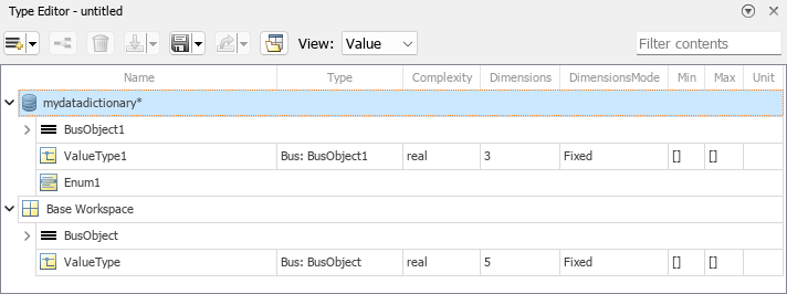
Docked Type Editor displaying types in a data dictionary and the base workspace

Create Simulink.Bus objects from bus element port specifications

To create Simulink.Bus objects from buses at bus element ports, use the Simulink.Bus.createObject function.

Signal Editor tool updates

The Signal Editor tool has these updates:

Move signals in Signal Editor

The Signal Editor tool Move button Move has been removed. The move action is now combined with the select action. You can select and move one point, two contiguous points on the same line, or the entire plot. In releases prior to R2024a, the Move button enabled you to move only the entire plot. For more information, see Move Signal Points in Signal Editor.

Change x- and y-axes limits

Change plot x- and y-axes limits in the SignalX.Scenario Axes Properties panes. When you change the limit, the plot adjusts your view. For an example, see Change x- and y-axes limits.

Synchronize signals by time

To synchronize all the signals in open plots by time (x-axis), select Synchronize X-limits in the Synchronize.SignalX Axes Properties pane. Use this setting to also synchronize zooming, panning, and fit-to-plot. For an example, see Add and Edit Multidimensional Signals.

Signal and associated table data selection now linked

Signals in the plot or data table are now linked. Selecting a point in the plot highlights the associated data in the table. Vice versa, selecting a data point in the table highlights the associated point in the plot. Deleting a point in the plot deletes the associated data in the table. Vice versa, deleting a data point in the table deletes the associated point in the plot. For an example, see Add and Edit Multidimensional Signals.

Move signal points in Create Signal live task

The Create Signal Move button Move has been replaced by the Select and Move point(s) button Select and Move point(s) button. The move action is now combined with the select action. This button enables you to select and move one signal point, two contiguous signal points on the same line, or the entire plot. In releases prior to R2024a, the Move button enabled you to move only the entire plot. For more information, see Create Signal.

Access context-sensitive help in Root Inport Mapper

The Root Inport Mapper tool has added access points for context-sensitive help:

  • In the Scenarios pane title bar, click the context menu icon.

    Scenarios pane context menu

  • Right-click a row of the Scenarios pane.
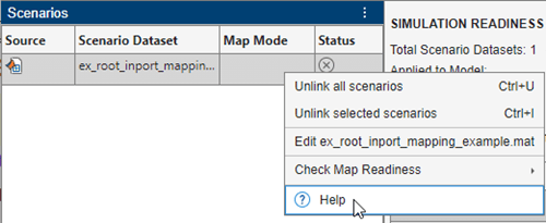
    Scenarios table context menu

fixdt supports C/C++ code generation

The fixdt function now supports C/C++ code generation.

New configuration parameters for finer control of parameter overflow and precision loss diagnostics

Simulink has new configuration parameters that give you finer control over filtering of parameter overflow and precision loss diagnostics.

Access these new parameters in the Diagnostics > Data Validity pane of the Configuration Parameters dialog box:

Diagnostics > Data Validity pane of the Configuration Parameters dialog. The four new configuration parameters are highlighted.

Parameter Quantization Advisor: Toolstrip-based UI

The Parameter Quantization Advisor interface now includes a simplified toolstrip with new features.

  • Filter data:

    • Use the Overflow, Underflow, and Precision Loss filters to show or hide diagnostic data.

    • Use the Parameters Without Diagnostics filter to show or hide issues that are lossless and quantization issues that are filtered out due to Configuration Parameter settings.

  • Open the Configuration Parameters dialog box directly from the app using the Model Settings button.

  • Refresh data in the app using the Refresh Data button.

  • Diagnostics that are suppressed with Simulink.SuppressedDiagnostic are now automatically hidden in the app. You can use the Parameters Without Diagnostics filter to display these diagnostics in the app.
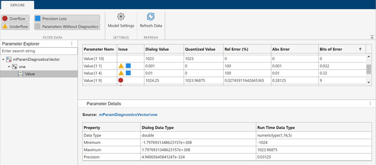
Screenshot of Parameter Quantization Advisor app showing new toolstrip.

Parameter Quantization Advisor: Support for structures, bus, and Simulink.Parameter objects

The Parameter Quantization Advisor now supports structures, bus objects, and Simulink.Parameter objects.

To open the app for a Simulink.Parameter object, at the MATLAB command prompt, enter this command.

parameterQuantizationAdvisor('model name','Simulink.Parameter object name')

To open the app for a parameter with a structure value, at the MATLAB command prompt, enter this command.

parameterQuantizationAdvisor('block path','parameter name')

Use symbolic expressions for string data types

Starting in R2024a, you can use symbolic expressions for the maximum length of string data types for a subset of Simulink blocks. Symbolic expressions allow you to:

  • Update the maximum length simply by updating the corresponding symbolic expression values.

  • Avoid rebuilding the model each time you need to update the maximum length.

For more information on creating string data types, see stringtype.

 Functionality being removed or changed

Error reported when you load MPT objects last created or modified before R2012b

Behavior change

In R2024a, if you load a .mat file or a .slx file that contains mpt.Signal or mpt.Parameter objects that were last created or modified before R2012b, Simulink reports one of these error messages:

  • Class mpt.CustomRTWInfoSignal not supported in R2024a and removed in R2024b. Migrate instances of this class to the new supported class.

  • Class mpt.CustomRTWInfoParameter not supported in R2024a and removed in R2024b. Migrate instances of this class to the new supported class.

To resolve this error, load the .mat file or .slx file in a release later than R2012a and before R2024a. Then resave the file.

Block Enhancements

Dock dashboard panels

You can now dock dashboard panels to the Simulink Editor window. You can use the docked panel to monitor signals and control parameters during simulation without covering the model diagram in the canvas.

To dock a panel, select the panel. If the panel has multiple tabs, select any tab. Then, pause on the ellipsis (…) that appears. In the action menu that expands, click the Dock button .

To return the docked panel to the canvas, click the Open in canvas button .

For more information, see Dock Panels.
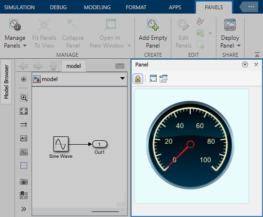
A panel is docked to the Simulink Editor. The panel has two tabs. The selected tab contains a Circular Gauge block.

Use Expand Scalar block to create scalar expanded matrices

To create scalar expanded matrices, use the new Expand Scalar block.

New Array Processing Subsystem block

Use the new Array Processing Subsystem block to apply an algorithm to each element of a matrix, similarly to the arrayfun function. Use Array Processing Subsystem blocks to efficiently process large input matrices such as image and video data.

New Pixel Processing Subsystem block

Use the new Pixel Processing Subsystem block to apply an algorithm to each pixel in multichannel image data and derive a single-channel output image. The Pixel Processing Subsystem block processes n-dimensional input data like a Neighborhood Processing Subsystem block that has a 1-by-1-by-n neighborhood size.

For an example of how to use the Pixel Processing Subsystem block, see Convert RGB Image to Grayscale by Using a Pixel Processing Subsystem Block.

MinMax block supports specified dimensions

The MinMax block now enables you to find minimum or maximum values over a specified dimension using these new parameters:

  • Apply over — Apply function over all or specified dimensions.

  • Dimension — Dimension over which to apply the function.

Sum, Sum of Elements, Subtract, Add, Product, Matrix Multiply, and Product of Elements blocks have new parameter names

These parameters for the Add, Sum, Sum of Elements, Subtract, Product of Elements, and Product, Matrix Multiply blocks have been renamed.

BlockNew Parameter NameOld Parameter Name
Sum, Sum of Elements, Subtract, AddApply overSum over
Product, Matrix Multiply, Product of ElementsApply overMultiply over

Width block supports symbolic dimensions

The Width block has these changes:

  • Support for symbolic dimensions.

  • New parameter, Always use constant sample time.

Data store blocks support indexing for symbolic dimensions

The Data Store Read and Data Store Write blocks now support indexing when the Data Store Memory block uses symbolic dimensions.

From Spreadsheet block supports relative and full paths for File name

The From Spreadsheet block now supports relative and full paths for File name for simulation and code generation. In releases prior to R2024a, if you specified a relative path for File name, the From Spreadsheet block changed the relative path to the full path during code generation.

Support for variable-size input signals in Discrete Filter and Discrete Transfer Fcn blocks

The Discrete Filter and the Discrete Transfer Fcn blocks support variable-size input signals when you set the Input processing parameter to Columns as channels (frame based).

When the input is a variable-size signal, you can change the frame size (number of rows) of the signal during simulation but the number of channels (columns) must remain constant.

Write to base workspace variable or variable in data dictionary using Parameter Writer block

Starting in R2024a, you can use a Parameter Writer block to write to a base workspace variable or a variable that you create in Simulink.data.Dictionary. To configure a Parameter Writer block to write to such a variable, in the Block Parameters dialog box:

  • Select Base workspace variable from Destination parameter options.

  • Enter the variable name in Workspace variable name field.

Before R2024a, you could only write to a model workspace variable or a block parameter using Parameter Writer block. The new parameter, Destination replaces the existing Access model workspace variable parameter.
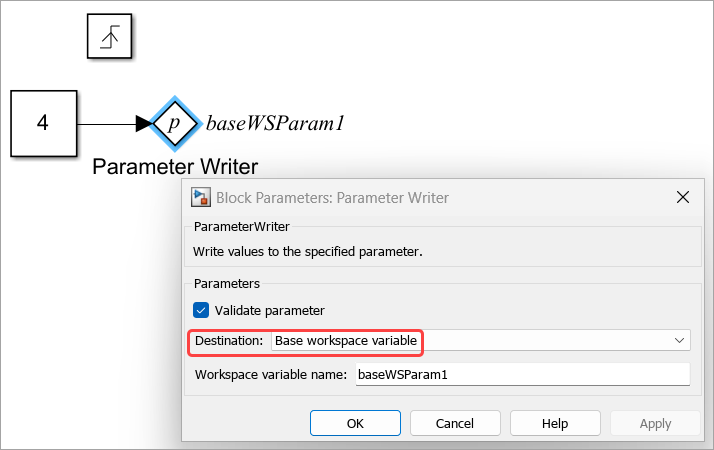
Parameter Writer block that writes to base workspace variable.

Monitor signal values during simulation using customizable Half Gauge and Quarter Gauge blocks

To monitor signal values during simulation, you can now use Half Gauge and Quarter Gauge blocks that can be customized to look like gauges in real systems. The new blocks are located in the Customizable blocks library. The blocks are functionally the same as the Circular Gauge block but are visually pre-configured to look like gauges shaped as a half- and quarter-circle, respectively.

A Half Gauge block is next to a Quarter Gauge block, The half gauge is shaped like a half-circle, and the quarter gauge like a quarter circle, with the scale running along their outer perimeter.

Display block from Customizable Blocks library can display strings

The Display block from the Customizable Blocks library can now connect to and display signals that are strings.

Deploy dashboard panel as web app or standalone desktop app

With a Simulink Compiler license, you can now deploy a dashboard panel, packaged with the model to which the panel connects, as a standalone desktop app or as a web app. You can use the app to operate the controls and monitor the displays on the panel independent of Simulink.

To learn how to deploy panels, see Deploy Dashboard Panel as App.

Dashboard panels support Windows display scaling of over 100%

Dashboard panels support Microsoft Windows display scaling values higher than 100%.

Programmatically add data to the Playback block

The Playback block now has a Signals parameter that you can use to retrieve information about signals in the block or add new signals to the block using the get_param and set_param functions.

For example, to add signals from the workspace to the Playback block programmatically:

  1. Use the Simulink.playback.createSignals function to create a Simulink.playback.Signal object for the signals you want to add to the Playback block. Specify the source of the data as the workspace, and list the variable names of the signals to be added.

  2. Use the set_param function to set the Simulink.playback.Signals object as the value of the Signals parameter.

pbSig  = Simulink.playback.createSignals("workspace","Variables",["x1","x2"]);
set_param("PlaybackModel/Playback","Signals",pbSig);

For more information, see Simulink.playback.Signal and Simulink.playback.createSignals.

Search for signals to add to the Playback block

When you use the Add Signals dialog box to add signals to the Playback block, you can now search for specific signals. As you type the signal name, the table of signals updates to display only the signal names that contain your search term. You can also refine your search to exclude partial matches, match specific capitalization, or use regular expressions to find signals that follow a certain pattern.

Animation showing how to narrow down search results. First, the search term sine (with a lowercase s) is used to find only those signals that contain the word sine in the name. Then, the option to use regular expressions is selected and the search term is changed to sine[1-4]. This finds only those signals with names that contain the word sine followed by a number between 1 and 4. Next, the option to exclude partial matches is selected. This limits the results to signals whose full names match the search term. For example, the signal named cosine1 is removed from the search results. Lastly, the option to match case is selected. Since the search term is all lowercase, only signals with lowercase names remain in the search results. The final list contains the following signals: sine1, sine2, sine3, and sine 4.

Support for target-specific code generation for C Function block

Starting in R2024a:

  • You can specify target-specific code for code generation interactively using the Code generation tab in the C Function Block Parameters dialog box. Before R2024a, you could specify the code only programmatically by using #ifndef MATLAB_MEX_FILE.

  • The target-specific code you specify does not need to be compatible with desktop MEX compilers.

  • You can embed the target-specific code in the model-generated code without optimizations.
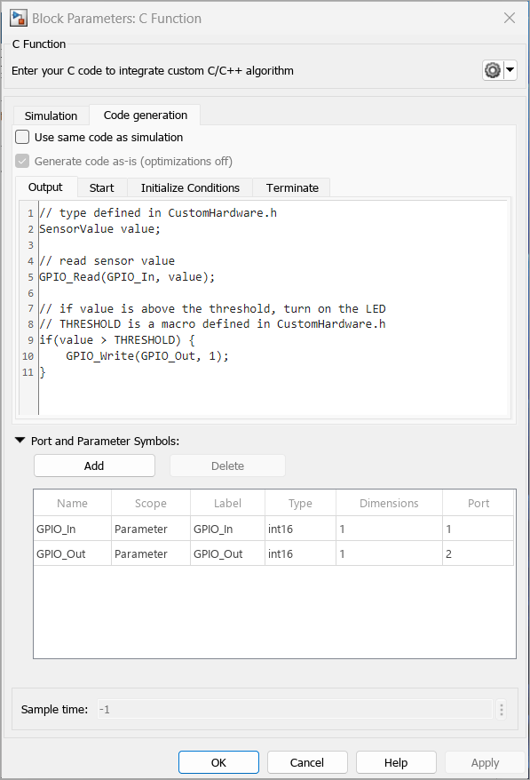
New Code generation tab in C Function Block Parameter dialog box.

Report error and warning messages in C/C++ code in C Function block

Starting in R2024a, you can report run-time errors and warnings in C/C++ code that you write in a C Function block. Use slError and slWarning to report run-time errors and warnings, respectively. Error messages indicate unexpected conditions in the code, and warning messages flag potential issues in the code. An error message terminates the simulation. If you see a warning message, you can either terminate or continue with the simulation. For more information, see Report Run-time Errors and Warnings in Simulink.

You can view the error and warning messages using the Diagnostic Viewer in the Simulink canvas.
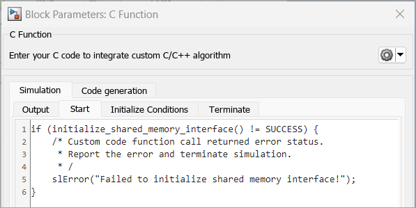
slError reports error at the start of C Function block simulation.

Specify custom code in C Function block

Starting in R2024a, you can specify your custom C code locally in a C Function block. For multiple C Function blocks, this change allows you to specify only the dependencies associated with the custom code for a specific C Function block. In the Block Parameters dialog box, click the down arrow next to Configure Custom Code settings button. icon and select Use Block Custom Code option.

Before R2024a, you could specify the code only globally using model configuration parameters.
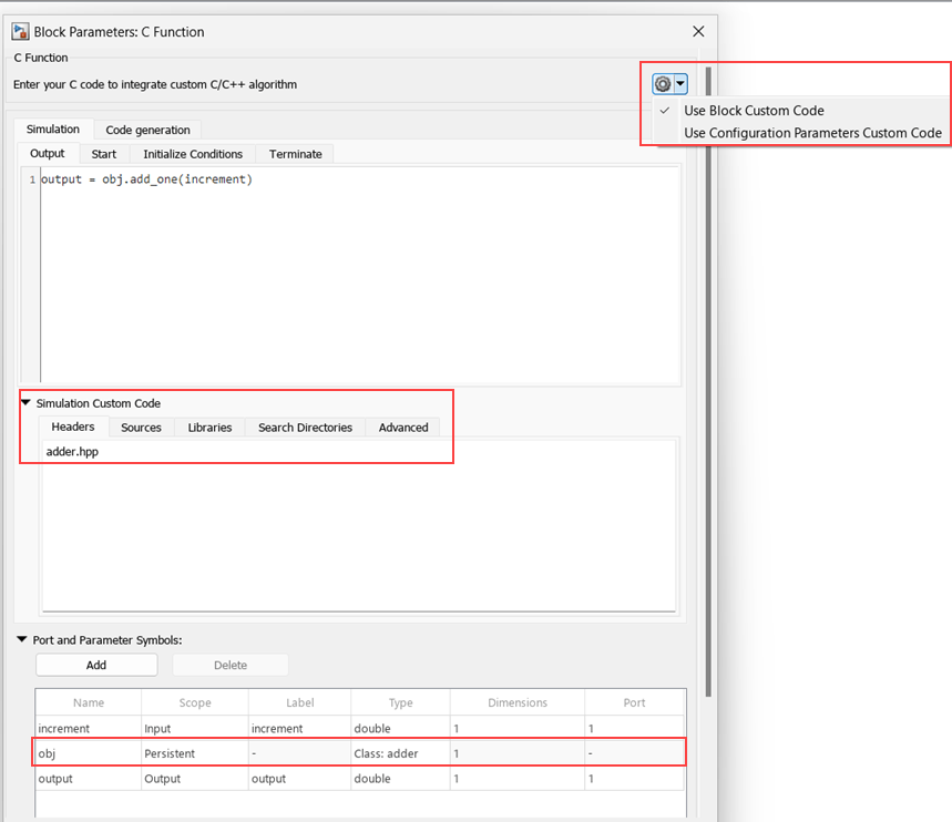
Specify custom code locally in C Function block.

Specify row-major and column-major arrays in custom code for C Function block

Starting in R2024a, you can specify row-major and column-major arrays by using the slSetRowMajor and slSetColumnMajor functions in the C Function block custom code. For more information, see Specify Row-Major and Column-Major Array Layouts in Custom Code.

Out Bus Element block: Specify additional elements and their attributes without adding blocks or bus objects

When a subsystem or model has an output bus element port, you do not need to specify a Simulink.Bus object or add Out Bus Element blocks to:

  • Add elements to the output port.

  • Specify attributes of the elements at the output port.

For more information, see Define Output Bus Without Extra Blocks or Bus Objects.

To programmatically add elements to the output bus without adding blocks to the block diagram, use the Simulink.Bus.addElementToPort function.

Bus element ports and function ports have more intuitive block interactions

When you interact with In Bus Element, Out Bus Element, Function Element Call, and Function Element blocks, the results of your actions are more consistent and clear.

When you press Ctrl and drag the blocks to a new position, you receive these options:

  • New Port — Create a port.

  • New Element — Add an element to the port. Out Bus Element and Function Element blocks support this option only when the dragged block represents an element of the port and not the full port.

  • Duplicate — Create a duplicate In Bus Element or Function Element Call block. Out Bus Element and Function Element blocks do not support duplication.

These actions consistently create a port:

  • Double-click the canvas. In the Quick Insert menu, start typing the name of one of the blocks. Then, select the block from the menu.

  • Copy and paste one of the blocks.

For more information about these blocks, see In Bus Element, Out Bus Element, Function Element Call, and Function Element.

Bus Selector block: Right-click elements in dialog box to access options

In the Block Parameters dialog box of a Bus Selector block, right-click elements and select the desired action.

  • Add to output — Add elements from the input bus to the block output.

  • Highlight source blocks — Highlight the source blocks of elements in the input bus.

  • Remove — Remove elements from the block output.

  • Remove all invalid elements — Remove all output elements that are not in the input bus. The invalid element names are red.

For more information, see Bus Selector.

Bus Selector blocks have more intuitive parameter names and interactions

When you interact with Bus Selector blocks, the results of your actions are more clear.

  • The Select elements button is now the Add to output button .

  • The Selected elements list is now the Output elements list.

  • The Output as virtual bus button is now the Output as virtual bus check box.

For more information, see Bus Selector.

Graphical Icon Editor: Reuse common icon elements using base part

Starting in R2024a, you can designate a part of a block icon as the base part, allowing all other parts of the icon to inherit its elements. Designating a base part has these advantages.

  • There is no need to duplicate common elements in each part, resulting in a lighter icon file.

  • Managing the icon is easier since any changes made to the base part of the icon propagate to all other parts of the icon.

For more information on pinning a part as a base part, see Render Multiple Variations of Same Block Icon Using Parts

Graphical Icon Editor: Evaluated mask workspace variables are supported as icon data

Starting in R2024a, you can access evaluated workspace variables as icon data. You can use these values to set conditional visibility, layout constraints, or text parameterization. Additionally, you can retrieve the integer values of enumerations assigned to the workspace variables.

The syntax to access the evaluated value of a mask workspace variable is:

value@maskWorkspaceVariable === value

For example, set the visibility condition for an icon element.

value@Parameter1 === "10"set the visibility condition using the evaluated value of the parameter
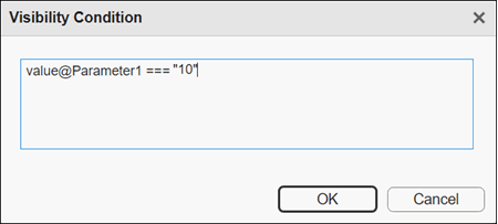
The syntax to access the evaluated value of an enumeration member is:

value@enumerationMember === "enumerationValue"

For example: Set the condition visibility for an icon element based on the evaluated value of the enumeration member.

value@open_orifices_pos === '2'

Previously, the condition was set as

open_orifices_pos === 'fluids.thermal_liquid.valves.directional_control_valves.enum.OpenOrifices3Way.PA'

For more information on evaluated parameters, see Set Visibility Condition Based on Evaluated Value of Parameters

Note

The supported datatypes for the resolved parameter are numeric, boolean, and string.

Graphical Icon Editor: Adapt block icon color to Simulink canvas color

Prior to R2024a, the block icon's default color was white, regardless of the canvas color. However, starting from R2024a, you now have the option to make the background of the block icon transparent, allowing the Simulink canvas color to show through. You can also set, the background color of closed shape elements inside the block to inherit the Simulink canvas color. For more information, see the icon properties pane table in Edit Properties of Block Mask Icon and Its Elements.

Graphical Icon Editor: Repeat icon elements on multiple ports

Starting in R2024a, you can use the Repeat Parameterization option to repeat icon elements on multiple ports of a block. You can choose to repeat the elements based on the position of the ports.

For example, you can repeat an icon element for all the left ports of the block and left align the elements of the block.

To repeat an icon element, right-click the element and select Parameterize from the context menu. In the Element Parameterization panel, select the position of the ports and the alignment of the elements for each port.

For more information on repeating icon elements, see Repeat Icon Elements on Multiple Ports.

Graphical Icon Editor: Preview variations of a block icon

Starting in R2024a, you can preview variations of a block icon based on visibility conditions and parameters using the options Parameter Variations and Width Height Variations. These options are available along with other preview options in Simulink canvas. For more information, see Design Complex Block Icon Using Parts and Preview the Variations

Specify height, width, and alignment for an image in a block icon

You can now specify image alignment details by using mask icon drawing commands, including alignment to the left, right, top, and bottom margins. You can also specify the width and height of the image as a percentage of the width and height of the block. For more information, see image.

For example:

image("path\to\image",[leftMargin, topMargin, rightMargin, bottomMargin, widthPercentage, heightPercentage])

image("airplane.jpg",[0,0,10,10,90,90])

Airplane image aligned with margins

Add parameters from base class in system object masks

Starting in R2024a, the Base Class Property parameter in a system object mask allows you to access available parameters from the system object file and modify the mask by adding parameters inherited from the base class. You can add or remove parameters from the base class, but it is not possible to remove parameters from the derived class. This ensures that the necessary parameters and functionality from the derived class are retained in the mask.

For more information, see Create and Customize MATLAB System Icon and Dialog Box Using Mask Editor.

PID Controller Blocks: Use derivative signal from external source

The PID controller blocks now allow you to supply the derivative of the plant signal y directly as an input to the block. This is helpful when you have the derivative signal available in your model and want to skip the computation of the derivative inside the block.

To enable the input port for supplying the derivative, select a controller type that has derivative action and enable the Use externally sourced derivative parameter.

Report runtime diagnostics for MATLAB System block in rapid accelerator mode

Report runtime errors for MATLAB System blocks when simulating in rapid accelerator mode by using one of these options:

  • Open the Configuration Parameters window. In the Modeling tab, click Model Settings. In the Configuration Parameters window, click Simulation Target, expand Advanced Parameters, and set the Enable memory integrity checks configuration parameter to Always on.

  • Use the set_param function to set the SimIntegrity parameter to 'alwaysOn'. For example, to enable diagnostics for a model named model_name, enter this command:

    set_param('model_name','SimIntegrity','alwaysOn');

Simulate FMU without defining bus objects or enumeration classes

You can now simulate an FMU that contains ports with bus or enumeration data types without having to manually define a bus object or enumeration class in the current Simulink session. The FMU block uses the metadata inside the modelDescription.xml file to determine the signal attributes for bus and enumeration type ports. This enables downstream and upstream blocks to inherit enumeration data type and downstream blocks to inherit bus data types. To enable direct simulation and propagation, open the FMU dialog box and set Type Object attribute to Inherit:auto for input and output ports with enumeration data types and Auto generate for output ports with bus data types.
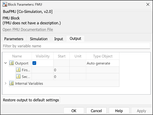
Select auto generate for Type Object attribute for the ports

Generate binary for FMU from source code

You can now generate binaries of FMUs on the corresponding platforms from its source code using the fmudialog.compileFMUSources function. For example, you can use this function to generate the Linux binary for an FMU that includes the source code but does not include the binary required for simulation on Linux platform.

Improve simulation performance of Python functions integrated into Simulink using Python Importer

Starting in R2024a, the simulation performance of the blocks generated by Python Importer, which integrates Python functions into Simulink, is improved by generating C-wrappers that are used to call the specified Python functions. This enhances the simulation performance of the blocks, enables simulation in rapid accelerator mode, and supports simulation in model reference with accelerator mode. You will need to have Python installed in your system to perform the simulation.

This enhancement is not supported for Python functions that are defined inside classes.

Launch external debugger from Simulink for debugging FMU

You can now directly launch an external debugger for debugging FMU from Simulink without manually configuring the external debugger to connect to Simulink.

Use the fmudialog.compileFMUSources function with 'DebugMode' argument set to 'on' to generate debugging information for an FMU that contains its source code.

To launch the external debugger, go to the Debug tab in Simulink and select Set Breakpoints in Custom Code option.
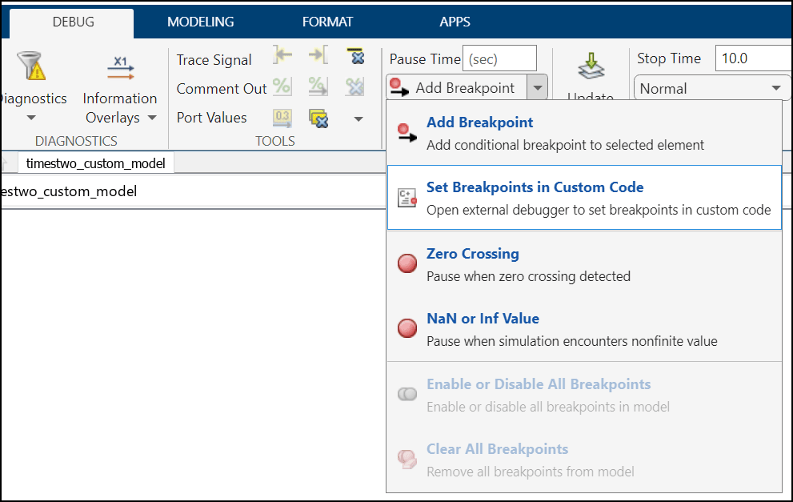
Launch external debugger from the debug tab of Simulink using Set Breakpoints in Custom Code option from drop-down

The Select Entities to Debug dialog box lists the entities that can be debugged. The FMUs that can be debugged are listed under FMU Blocks. Select the FMU that you want to debug and move them to Selected Entities.

Click Open to launch the external debugger.
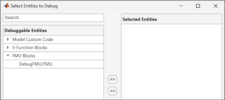
Dialog box that lists entities that can be debugged

Assign units to ports and parameters in S-Function Builder

Starting in R2024a, you can assign units to ports and parameters in S-Function Builder.

Use the Simulink.SFunctionBuilder.update function to assign units to ports or parameters. For example, the following code assigns m/s as the unit for the first input of s-function AddOne.

Simulink.SFunctionBuilder.update('AddOne','Input','u0','Unit','m/s');

You can also specify units in the Units column of Ports and Parameters table in the S-Function Builder.
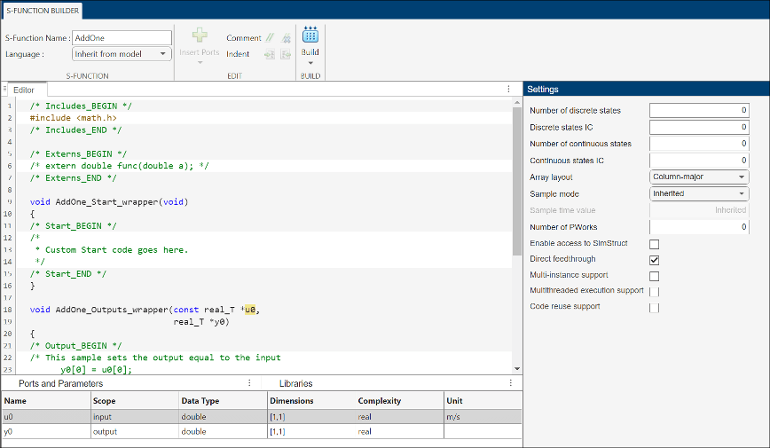
S-Function Builder window with units

Enhancements to FMU block importing FMU compatible with FMI 3.0 standards

FMU block importing an FMU that is compatible with FMI 3.0 standards has the following enhancements. Starting in R2024a you can:

  • Generate code for model that contains the FMU.

  • Create FMU from a model that contains FMU.

  • Simulate model with FMU in Rapid Accelerator simulation mode.

  • Export model with FMU to a protected model.

  • Use the FMU inside a model reference in Accelerator simulation mode.

Simulate FMU containing Linux binary on Windows

You can now use the FMU to import and simulate an FMU, compatible with FMI 2.0 standards, with Linux binary on Windows platform.

You will need to install Windows Subsystem for Linux (WSL) Version 2.0.9.0 or newer and FMU Builder for Simulink support package to import and simulate the FMU with Linux on Windows.

Note

This feature requires Simulink Compiler license.

 Functionality being removed or changed

Multiport Switch block has runtime error when input has floating point value

Behavior change

The Multiport Switch block now issues a runtime error when the control signal in the first port has a floating point value that exceeds the datatype range of integers. This range includes Inf and NaN.

Connection to Hardware

Hardware boards and minidrones: Documentation for hardware support packages moved to Simulink documentation

Starting R2024a, the documentation for the following support packages will be included in the Simulink documentation and all updates will be announced in the Simulink release notes.

  • Simulink Support Package for Android® Devices

  • Simulink Support Package for Arduino Hardware

  • Simulink Support Package for LEGO® MINDSTORMS® EV3 Hardware

  • Simulink Support Package for Parrot® Minidrones

  • Raspberry Pi Blockset

In previous releases, the support package documentation was installed when you installed the support package software. To access archived release notes from the previous release, click one of the following links.

Android Devices: Execute multiple tasks, detect task overruns, and profile code execution times in Android Simulink models

Simulink Support Package for Android Devices now supports these features that facilitate parallel processing of tasks, reduce the risk of timing while executing a task, and enhance overall performance in a real-time system.

For more information, see Model Multitask Execution and Real-Time Code Execution Profiling on Android Device and Model Code Profiling for Multiband Dynamic Range Compression System Using Android Device.

Arduino Hardware: Configure static IP address

Starting R2024a, you can now configure a static IP address and specify the DNS server address, gateway address, and the subnet mask for these Arduino hardware boards.

  • Arduino compatible ESP32 — WROOM

  • Arduino compatible ESP32 — WROVER

  • Arduino MKR 1000

  • Arduino MKR Wi-Fi 1010

  • Arduino Nano 33 IoT

This release also introduces a new option, Static IP — Advanced, under Configuration Parameters > Target hardware resources > WiFi properties > IP address assignment, which you can use to configure networking properties of these Arduino boards.

Arduino Hardware: Read and write data to on-board Arduino EEPROM

This release introduces the On-board EEPROM Read and On-board EEPROM Write blocks, which you can use to read from and write to the byte-addressable Arduino on-board EEPROM. You can build and deploy the blocks on these Arduino hardware boards.

  • Arduino Mega 2560

  • Arduino Uno

  • Arduino Leonardo

  • Arduino Micro

  • Arduino Nano 33 IoT

Arduino Hardware: Handle hardware interrupts from ADC and PWM peripherals on Arduino AVR hardware

Simulink Support Package for Arduino Hardware now supports handling hardware interrupts generated by the ADC and PWM peripherals for the AVR family of Arduino hardware. Earlier releases supported handling of hardware interrupts from external pins only.

  • Hardware Interrupt — Use this block to trigger a downstream function-call subsystem from an interrupt service routine.

  • PWM — Use this block to generate a square wave on the specified output pin of the Arduino AVR hardware.

  • Analog Input — Use this block to read the ADC register value at the specified pin of the Arduino AVR hardware.

Arduino Hardware: Control color and brightness of Adafruit NeoPixel strip

This release introduces the NeoPixel block, which you can use to control the color and brightness of individual pixels on the NeoPixel strip. The pixels on the strip are individually addressable RGB and RGBW LEDs that you can use to create different light patterns and effects.

Arduino Hardware: Deploy Simulink models to Teensy 4.0 and 4.1 hardware boards

Simulink Support Package for Arduino Hardware now supports deploying Simulink models on the Arduino compatible Teensy 4.0 and 4.1 hardware boards. The Hardware board drop-down list in the Configuration Parameters dialog box now includes the Teensy 4.0 (Arduino compatible) and Teensy 4.1 (Arduino compatible) options. A new parameter, Terminate Teensy Loader application post deployment has been added under Configuration Parameters > Target hardware resources > Host-board connection

You can use these blocks from the support package library with the Arduino Teensy hardware boards.

Currently, the support package does not support simulating a model to the Arduino compatible Teensy 4.0 and 4.1 hardware boards in the Connected IO and PIL modes.

Arduino Hardware: Use secondary I2C and SPI modules

Starting R2024a, Simulink Support Package for Arduino Hardware supports utilizing the secondary I2C and SPI modules on these Arduino hardware boards.

Secondary I2C Enabled Arduino BoardsSecondary SPI Enabled Arduino Boards
Arduino DueArduino compatible ESP32-WROOM
Arduino compatible Teensy 4.0 and 4.1Arduino compatible ESP32-WROVER

Earlier, you could use only one I2C and SPI module on the Arduino boards.

Arduino Hardware: Detect COM ports automatically using VID and PID numbers

Starting R2024a, Simulink Support Package for Arduino Hardware now automatically detects the COM port of the host machine to which you have connected the Arduino board by using the vendor identification (VID) and product identification (PID) numbers. This release also introduces a new parameter, Verbose output under Configuration Parameters > Target hardware resources > Build Options, which provides additional diagnostics about the Simulink models that you have deployed to the Arduino board.

Arduino Hardware: Save code profiling summary and analysis data

Starting R2024a, Simulink Support Package for Arduino Hardware provides the Summary data only and All data options for saving code profiling data. To access these options, navigate to Configuration Parameters > Code Generation > Verification path, select Measure task execution time (Embedded Coder), and specify an option under Save options (Embedded Coder).

  • Summary only data — Use this option to save only code profiling summary data in the base workspace.

  • All data — Use this option to save the code profiling measurement and analysis data in the base workspace. This option also enables the streaming of execution times to Simulation Data Inspector during simulations.

Arduino hardware boards with SAM core architecture supports task execution measurement with the Metrics Only saving option. For more information, see Code Execution Profiling for Arduino Hardware in External Mode.

Arduino Hardware: Connected IO support for blocks

You can now deploy a Simulink model to an Arduino board in the Connected IO mode when it contains the following blocks.

Arduino Hardware: Repurpose analog pins as digital pins

Starting R2024a, when using Simulink Support Package for Arduino Hardware, you can repurpose the analog pins as equivalent digital pins on all the Arduino hardware boards. You can also use analog pins in these blocks.

Arduino Hardware: Read linear acceleration, angular velocity, and temperature using ADIS16505 sensor

Simulink Support Package for Arduino Hardware now supports interfacing the ADIS16505 sensor connected to the SPI bus of Arduino hardware. You can use the new ADIS16505 6DOF IMU Sensor block to measure linear acceleration and angular velocity along the x-, y- and z- axes, and to measure temperature.

Raspberry Pi Hardware: Customize Raspberry Pi OS setup

When installing Raspberry Pi Blockset, you can download and install only select third-party libraries and packages on your Raspberry Pi operating system. Use the Hardware Setup window to specify the libraries and packages. This update allows you to efficiently manage the resources of your Raspberry Pi operating system by avoiding unnecessary downloads. For more information, see Modularize Installation of Third-Party Packages and Libraries for Raspberry Pi Hardware.

Raspberry Pi Hardware: Support for 64-bit Bullseye Raspberry Pi OS

Starting R2024a, you can use the Raspberry Pi Resource Monitor App app with the 64-bit Bullseye operating system. Earlier, the app supported the 32-bit Bullseye and Buster Raspberry Pi operating system.

Starting this release, you can also simulate a Simulink model in the Normal mode with Connected IO with the 64-bit Bullseye Raspberry Pi operating system

Raspberry Pi Hardware: Support for Raspberry Pi Compute Module 4 hardware board

Starting R2024a, you can use Raspberry Pi Blockset to deploy Simulink blocks and models to the Raspberry Pi Compute Module 4 hardware board.

Raspberry Pi Hardware: Stream video over RTSP using Video Stream Transmit block

This release introduces the Video Stream Transmit block, which you can use to stream video to a network using the real-time streaming protocol (RTSP). For effective use of network bandwidth, you can encode the video stream using the H264 or JPEG protocols. For more information, see Stream Video Over Network Using Raspberry Pi Video Stream Transmit Block.

Raspberry Pi Hardware: Use secondary I2C and SPI modules

Starting R2024a, Raspberry Pi Blockset supports utilizing the secondary I2C and SPI modules on the Raspberry Pi Zero 2 W, 3B, 3B+, 4B, and Compute Module 4 hardware boards. Earlier, you could use only one I2C and SPI module on the Raspberry Pi hardware boards.

Raspberry Pi Hardware: Deploy dashboard blocks using Simulink Online

Starting R2024a, you can deploy all the dashboard blocks in the Simulink Customizable Blocks library to your Raspberry Pi hardware board using Simulink Online. For more information, see Connect to Raspberry Pi Hardware Board in Simulink Online.

Raspberry Pi Hardware: Support added for Apple silicon Mac hardware

Starting R2024a, you can use the Raspberry Pi Blockset to build and deploy Raspberry Pi applications on Apple silicon Mac computers.

MATLAB Function Blocks

Specify header file within coder.ceval command

Starting in R2024a, you can specify a header file for a C/C++ function within a coder.ceval (MATLAB Coder) call by using the "-headerfile" name-value argument. Prior to R2024a, you had to specify a header file separately by calling coder.cinclude (MATLAB Coder) before coder.ceval.

For example, to call the C function foo declared in header file foo.h with input argument x, include this coder.ceval command in your MATLAB code:

y = coder.ceval("-headerfile","foo.h","foo",x);

Use a for-loop that iterates over a cell array inside MATLAB Function block

In R2024a, you can use a for-loop that iterates over a cell array inside a MATLAB Function block. The size of the first dimension of the cell array must be equal to 1. This usage supports iterating over both homogeneous and heterogeneous cell arrays.

For example, define the MATLAB function addStructFields that adds all the fields of an input struct s. In the function code, access the fields of s by looping over the cell array that fieldnames(s) returns.

function out = addStructFields(s)
out = 0;
for f = fieldnames(s)'
    out = out + s.(f{1});
end
end

Use addStructFields to create a MATLAB Function block that adds all elements of an input bus signal and outputs the sum.
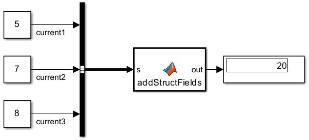
Simulink model that adds all bus elements using a MATLAB Function block.

Use uint32 enumerations greater than intmax("int32") inside MATLAB Function blocks

Starting in R2024a, you can use MATLAB enumerations derived from base type uint32 with values greater than intmax("int32") inside MATLAB Function blocks.

Enumerations with values greater than intmax("int32") are not supported as input to or output from MATLAB Function blocks.

Prior to R2024a, usage in MATLAB Function blocks supported uint32 enumeration values less than or equal to intmax("int32") only.

See Code Generation for Enumerations.

Control function inlining at the function call site using coder.inlineCall and coder.nonInlineCall

Starting in R2024a, you can call functions using coder.inlineCall (MATLAB Coder) and coder.nonInlineCall (MATLAB Coder) to instruct the code generator whether or not to inline the called function. The coder.inlineCall and coder.nonInlineCall functions override coder.inline directives in the called function.

For example, you can inline function foo and prevent the inlining of function bar in the generated code by calling foo and bar in your MATLAB code using coder.inlineCall and coder.nonInlineCall, respectively.

...
coder.inlineCall(foo);
coder.nonInlineCall(bar);
...

The coder.inlineCall and coder.nonInlineCall functions are subject to the same limitations as the coder.inline directive.

Generate code for alternate execution paths depending on whether configuration settings support unbounded variable-size arrays

In R2024a, you can use the coder.areUnboundedVariableSizedArraysSupported function inside MATLAB Function blocks. The return value of this function depends on whether you perform model simulation or code generation.

  • During model simulation, this function returns the state of the configuration parameter Dynamic memory allocation in MATLAB functions.

  • During code generation, this function checks the state of the configuration parameters Dynamic memory allocation in MATLAB functions and Support: variable-size signals. If both of these parameters are enabled, the function returns true. Otherwise, it returns false.

In both situations, the return value of coder.areUnboundedVariableSizedArraysSupported indicates whether current configuration settings support unbounded variable-size arrays.

In MATLAB execution, the coder.areUnboundedVariableSizedArraysSupported function always returns true.

For a demonstration of this functionality, consider the MATLAB function sumOfOneToN that computes the sum of the first n natural numbers in two different ways.

function out = sumOfOneToN(n)
if (coder.areUnboundedVariableSizedArraysSupported)
    out = sum(1:n);  % Uses unbounded variable-size array
else
    out = n*(n+1)/2; % Does not use unbounded variable-size array
end

Model simulation with dynamic memory allocation enabled executes the if branch in the function sumOfOneToN. This branch uses an unbounded variable-size array to compute the output.

By contrast, model simulation with dynamic memory allocation disabled executes the else branch in the function sumOfOneToN. This branch does not use unbounded variable-size arrays to compute the output.

Code generation for more toolbox functions

In R2024a, you can generate code for many additional toolbox functions and objects. For a list of all functions and objects that are supported for code generation, see:

These are links to the release notes of some toolboxes that added code generation support in R2024a:

Computer Vision Toolbox

See MATLAB Coder Support: Generate C and C++ code using additional functions (Computer Vision Toolbox).

Image Processing Toolbox

See C Code Generation: Generate code from additional functions using MATLAB Coder (Image Processing Toolbox).

Signal Processing Toolbox

See Generate C/C++ code for signal generation and spectral analysis (Signal Processing Toolbox).

Wavelet Toolbox

See C/C++ Code Generation: Automatically generate code for wavelet functions (Wavelet Toolbox).

Modeling Guidelines

New High-Integrity System modeling guidelines

This table lists the high-integrity system modeling guidelines introduced in R2024a.

Removed or modified modeling guidelines

Starting in R2024a, these modeling guidelines have been removed or modified.

Modeling GuidelineDescription

cgsl_0101: Zero-based indexing

Removed

hisl_0046: Configuration Parameters > Simulation Target > Block reduction

Removed
hisl_0310: Configuration Parameters > Diagnostics > Model Referencing Configuration parameter Invalid root Inport/Outport block connection (ModelReferenceIOMsg) is no longer supported in the software, therefore, the parameter is removed from the modeling guideline.
hisl_0037: Configuration Parameters > Model ReferencingRemoved configuration parameter Pass fixed-size scalar root inputs by value for code generation from the guideline.

R2023b

New Features, Bug Fixes, Compatibility Considerations

New Model Finder user interface: Index, search, filter, and browse Simulink models in multiple databases

Model Finder has a new user interface (UI) to index, search, filter, and browse Simulink examples, models, and projects across multiple databases. Using multiple databases enables you to create separate indexes for similar set of models for easier maintenance.

To open the Model Finder UI, type modelfinderui in the MATLAB Command Window. The Model Finder UI has these sections:

  1. Search box — Text box to enter the search terms to find models.

  2. Configure Databases — Menu of the available databases to search. You can select a single database or multiple databases from the list to set the search location.

  3. Search Summary — Display of the examples, models, and projects matching the search query. For each match, the Model Finder UI displays a summary with the name of the example, model, or project; the matched search terms highlighted in yellow; names of MathWorks products, location of the model; and a button to open the example, model, or project.

  4. Recent — List of up to five recent examples, models, or projects you opened using the Model Finder UI.

  5. Filters — Filters to narrow down search results in response to your search query. The Model Finder UI displays the following filters:

    • Matched In — Locations of the text that matches the search terms. This includes the model description, annotation, or block.

    • Product — Names of the MathWorks products used by the examples, models, or projects.

    • Location — Paths to the Simulink models or projects.

    • Example Component — Names of the example components.

  6. Info Panel — Description of the example, model, or project, and the block count of the selected search result.

For more information on the Model Finder UI, see Model Finder.

To configure database settings, use these functions:

For more information on Model Finder, see Index and Search Models with Model Finder.
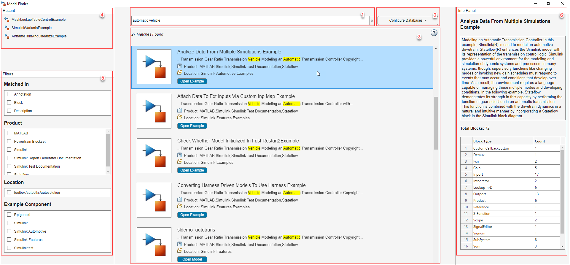
View of the Model Finder UI. Left side displays the recent search history and filters. In the middle, the search bar and search results are seen. The right side displays the info panel with the description and count of blocks of the selected search result.

New Connectors button to display different connections between blocks

Starting in R2023b, the Debug tab has a new Connectors button. This new Connectors button replaces the existing Function Connectors and Schedule Connectors buttons. This button also allows you to access all the connector options.

  • Three new connectors: State Connectors, Parameter Connectors and Data Store Connectors.

  • Two existing connector options: Function Connectors and Schedule Connectors.

Connector is a debug tool that displays the connection between different blocks in a Simulink model. To visually display the list of connectors, on the Debug tab, select Information Overlays > Connectors. The Connectors pane opens on the right side of the Simulink Editor. Select the required connector options to display the corresponding connectors. The arrow heads of the connector lines indicate the direction of signal flow.

This example shows a model with four connector options selected.
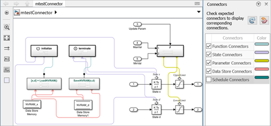
Model with four connector options selected

Create Model block ports without entering referenced model

Starting in R2023b, you can create ports on Model blocks without entering the referenced model the same way you can on a Subsystem block.

To create a port, pause on any of the four edges of the Model block. When your pointer turns into a cross, click. A new port appears on the edge you clicked, highlighted in blue.
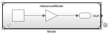
The pointer is a cross and is paused on the right edge of a Model block.

Pause your pointer on the new port. In the action menu that expands, select the type of port you want to create.
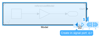
Action menu for port creation with the pointer paused on the Create in signal port button

Alternatively, to create a port, drag a signal line from the model element you want to connect to the edge of the Model block. Dragging from a port block creates a new port of the same type. For example, dragging from an Inport block creates a new input port. Dragging from a Subsystem or Model block port that represents a port block also creates a new port of the same type as the port block.

To delete an existing port, select the port and press Delete. To delete multiple ports, press Shift and select the ports. Then, press Delete.

For more information about creating Model block ports, see Add Ports to Model Reference Interface.

You can use the same approach to add ports to and delete ports from System Composer Reference Component (System Composer) blocks and AUTOSAR Blockset Component blocks that are linked to models.

Diagnostic Viewer: Faster reporting of diagnostic messages

Reporting of diagnostic messages when you load, simulate, or build a model shows improved performance.

For example, if you report 100,000 diagnostic messages on the Diagnostic Viewer, performance in R2023b is about 1.7x faster than in R2023a.

The approximate timings to report 100,000 warning messages for the model vdp using the function sldiagviewer.reportWarning in R2023b and R2023a are:

R2023b: 60.5 s

R2023a: 104.4 s

The reporting was timed on an Intel® Xeon® W-2133 CPU E5-1650 v4 @ 3.60GHz test system.

Share your feedback to analyze and improve the diagnostic messages

Give us your feedback for the diagnostic messages displayed in the Diagnostic Viewer when you simulate or build a model. Feedback will be used to improve the diagnostic message.

Click the Add Comment button Provide Feedback button next to the diagnostic message in the Diagnostic Viewer and enter your feedback in the text box. The character limit of the feedback is 1024 characters. To request help or report a technical bug, contact Technical Support at Contact Support.
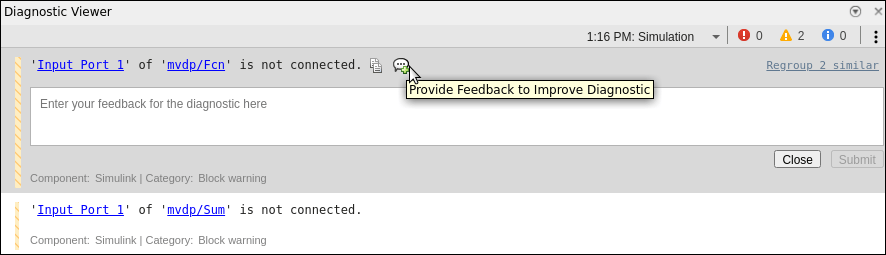
View of the Diagnostic Viewer with the text box to provide feedback.

Reload specific Simulink Toolstrip component using slUpdateToolstripComponent function

You can customize the Simulink Toolstrip by adding tabs that focus on specific workflows. When you create custom toolstrip components, you create a resources folder containing JSON files that specify component properties and, optionally, icon image files. You can edit the custom components by editing these files. To see the resulting changes in the toolstrip, you must reload the component.

Starting in R2023b, to see the changes in the toolstrip, instead of reloading the entire toolstrip using the slReloadToolstripConfig function, you can reload a specific component using the slUpdateToolstripComponent function. For the function input, specify the component name or the path to the parent folder of the resource folder.

For example, open Simulink and create a new custom toolstrip tab by entering these commands in the MATLAB Command Window.

Note

The first command places the current folder on the MATLAB path. For more information, see slCreateToolstripComponent.

slCreateToolstripComponent("componentName");
slCreateToolstripTab("propertiesFileName","componentName",Title="CUSTOM TAB");

A resources folder is created in the current folder. To change the tab title, open the resources folder and then the json folder. Open the propertiesFileName.json file and change "title": "CUSTOM TAB" to "title": "NEW". Save the file.

To reload the component, enter this command.

slUpdateToolstripComponent("componentName")

In the toolstrip, the title of the custom tab changes to New.

For more information about custom Toolstrip components, see Create Custom Simulink Toolstrip Tabs.

Open example models from the documentation or command line

Use openExample to open example models from the command line. For example, to open the f14 model, enter:

openExample('f14')
You can also access the example models from the documentation, including the examples listed in this table.

 Functionality being removed or changed

New keyboard shortcut for opening and hiding Property Inspector on macOS

Behavior change

Starting in R2023b, on macOS, the keyboard shortcut to open or hide the Property Inspector is command+option+O.

For more information about Simulink keyboard shortcuts, see Keyboard Shortcuts and Mouse Actions for Simulink Modeling.

Simulation Analysis and Performance

New Timing Legend with enhanced visualization and organization

The redesigned Timing Legend has visualization and organization that simplifies the analysis of timing information needed for the execution of the blocks in your Simulink model.

Starting in R2023b, you do not need to update the diagram for your model when changing the sample time visualization options or when launching the Timing Legend after model compilation.

Visualization in the Timing Legend is now more organized. Same-rate specifications are displayed as one row that you can expand for details. When using the Coloring, only the borders of the block display the color of the sample time rate. Check boxes for sample times also allow you to choose specific sample times to display. The Timing Legend now also displays base rate and scalar multipliers for analysis of the discrete time-lines.

Changes from the previous versions of the Timing Legend include:

  • The origin highlighting menu at the top of the Timing Legend is replaced by block path links. The block path links are available when you expand a sample time row.

  • All discrete sample times (for example, periodic partitions, discrete export function etc.) with the same sample time specification are now combined into the same row.

  • Triggered sample time rates are now visualized as their source sample times since it illustrates the sample rate that is driving the trigger.

  • Annotations for aperiodic partition, reset, initialize, reinitialize, and terminate sample times no longer use their event names as annotations. These sample times have their own concise annotations.

  • The colors used in the Timing Legend have been changed and reduced in number which provide more contrast to improve accessibility and usability.
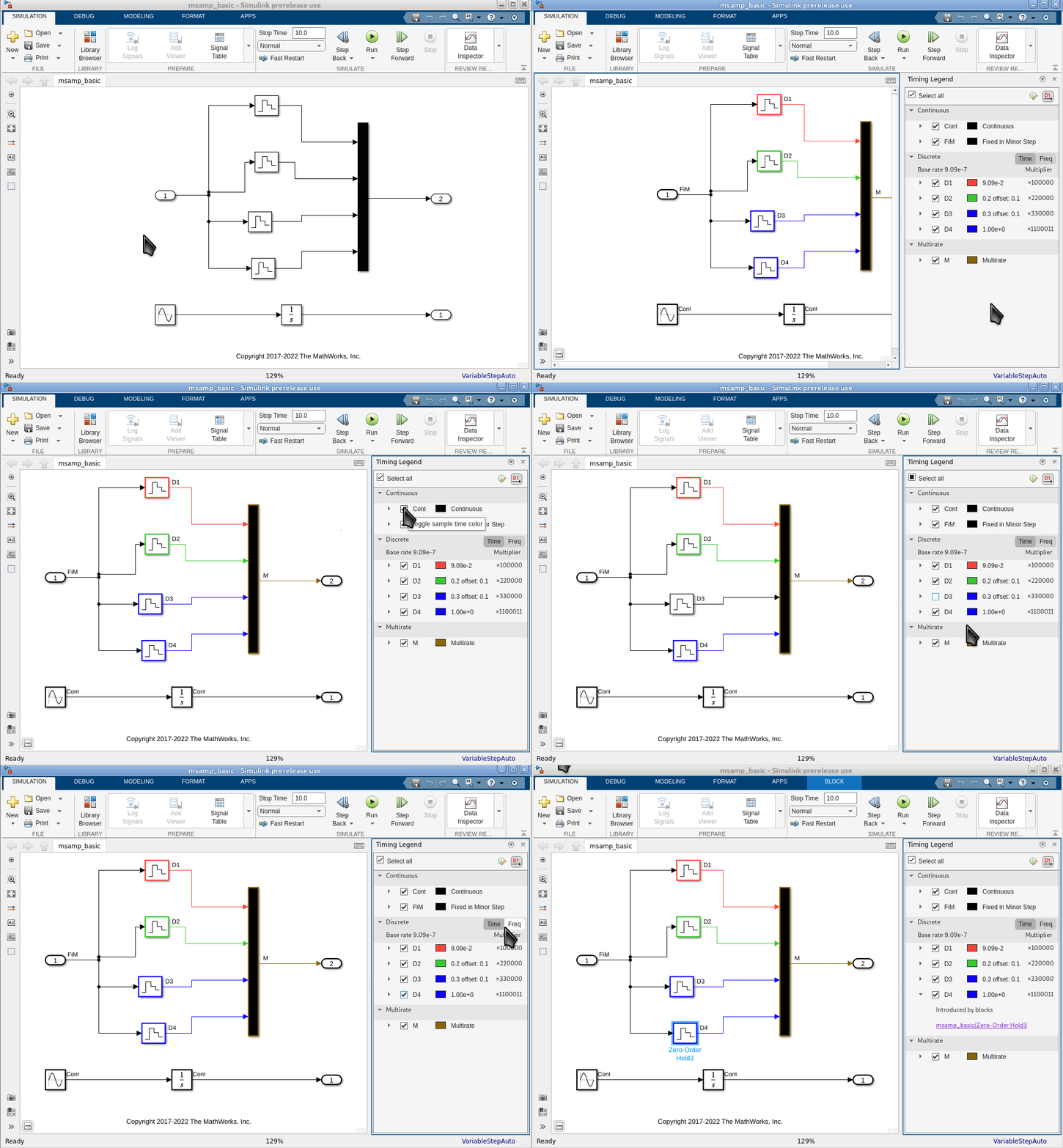
The image is a gif that shows that the sample time rows can be expanded. It also shows the new colors of the Timing Legend, and how these new colors are used to color only the borders of the block.

Specify a block to execute first or last in the execution order

Starting in R2023b, you can designate a Simulink block to execute first or last when the block is inside a nonvirtual subsystem or at the root level of a model. A subset of Simulink blocks support this new setting for the Execution Order property.

To configure a block to execute first or last, in the Block Parameters dialog box, from the Execution Order list, select First or Last. You must update the model (Ctrl+D) for this configuration to take effect.
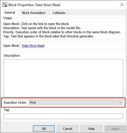
Execution Order configuration for Data Store Read block

This example shows the execution order of blocks at the root level of a model. The Execution Order property of the Data Store Read block and the Data Store Write block is set to First and Last, respectively. For more information, see Specify Block Execution Order, Execution Priority and Tag.
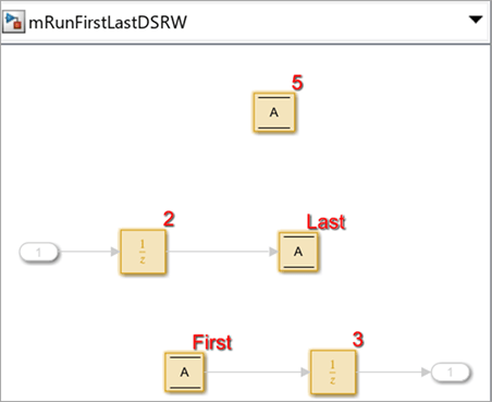
Model that represents execution order First or Last

By default, the Execution Order property of a block is set to Based on priority.

Support for unbounded variable-size signals in Simulink

Starting in R2023b, you can use unbounded variable-size signals to transmit data with unbounded size between components in a model. To specify variable-size signals as unbounded, set the signal size to Inf.

A subset of Simulink blocks and features support unbounded variable-size signals. These are a few different use cases.

  • Output unbounded variable-size signals from the Inport block.

  • Output unbounded variable-size arrays from the MATLAB Function block.

  • Specify buses containing data with unbounded size using a Simulink.BusElement object.

  • Specify signals containing data with unbounded size using a Simulink.Signal object.

For example, you need to configure the MATLAB Function block to output an unbounded variable-size array of size ([Inf 6]). To configure this block, in the Simulink Editor, on the Modeling tab, from Design gallery, select Model Explorer. In the Model Explorer window, select the MATLAB Function. Specify theSize as [Inf 6] and select the Variable size property.
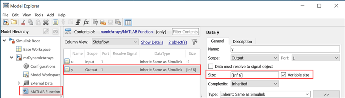
Set up MATLAB Function block to output unbounded variable-size array

This example shows four use cases when the Simulink blocks and objects are configured to use unbounded variable-size signals.
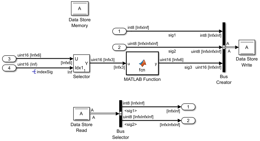
Model that uses unbounded variable-size signals

Nonvirtual mathematical operation blocks, including but not limited to the Gain block, Add block, Product, Matrix Multiply block, Math Function block, and Trigonometric Function block, do not support unbounded variable-size signals. To implement these math operations for unbounded variable-size signals, use the MATLAB Function block or S-Function block. For more information, see Unbounded Variable-Size Signals.

Keyboard shortcuts for Step Over, Step In, and Step Out debugging controls in Simulink Toolstrip

In R2023a, the Step Over, Step In, and Step Out buttons in the Simulink Toolstrip added the ability to advance a simulation block by block while paused within a time step. Starting in R2023b, you can use keyboard shortcuts to control these actions. The keyboard shortcuts for the buttons in the Simulink Editor are the same as the keyboard shortcuts for these buttons in the Stateflow Editor and the MATLAB Function Block Editor.

TaskShortcut
Step over

F10

On macOS, press Shift+Command+O.

Step in

F11

On macOS, press Shift+Command+I.

Step out

Shift+F11

On macOS, press Shift+Command+U.

Initialization time in simulation metadata includes time to set up simulation using Simulink.SimulationInput object

The timing information captured in the simulation metadata for simulations configured using Simulink.SimulationInput objects more closely matches the result of timing the call to the sim function using tic and toc. The initialization time now includes the time spent setting up the simulation based on the Simulink.SimulationInput object, such as:

  • Time to build model references, including time to set up workers for parallel builds

  • Time to run the presimulation callback function specified using the setPreSimFcn function

  • Time to set variable, block parameter, and model parameter values

The simulation metadata is returned as part of the Simulink.SimulationOutput object that contains all the simulation results. To view the timing information for a simulation, get the Simulink.SimulationMetadata object from the Simulink.SimulationOutput object and view the TimingInfo property of the Simulink.SimulationMetadata object.

out = sim(simIn);
simMeta = out.SimulationMetadata;
simTiming = simMeta.TimingInfo

Inf values supported for initial states data

When you specify an initial state for your model using the Initial state parameter, the data you specify can now contain Inf values, including when you specify the initial state as a Simulink.op.ModelOperatingPoint object. For example, you could load an initial state for the model with one or more Inf values in a test of the system response to invalid state values. In previous releases, the software issued an error when the initial state data contained Inf values.

Usability enhancements for viewing streaming data and text in the Simulation Data Inspector

In R2020b, the Freeze display button was added to the Simulation Data Inspector. In R2023b, this button has been and enhanced and renamed Hold .

  • Previously, when streaming signals to the Simulation Data Inspector, you could freeze the display to prevent the plots from wrapping or scrolling as new data came in. However, signals continued to plot until hitting the right edge of the plotting area.

    Now, the Simulation Data Inspector stops plotting data immediately when you hold the display. For more information about how to hold the display of streaming data, see View Streaming Data in the Simulation Data Inspector.

  • Previously, the Freeze display icon appeared only when streaming data.

    Now, the Hold button is always visible. When a simulation stops, the button becomes inactive.

The text editor now has a subplot menu and context menu like all other visualizations. You can click the three dots in the upper right corner of the text editor or right-click anywhere on the subplot to change the visualization, clear the subplot, maximise the subplot, or take a snapshot.
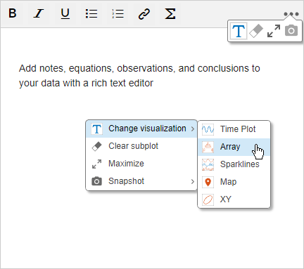
Add notes, equations, observations, and conclusions to your data with a rich text editor. In the upper right corner, the subplot menu is expanded to show the options to change the visualizations, clear the subplot, maximise the subplot, or take a snapshot. In the center of the text editor, the context menu shows the same menu choices with the Change visualization option expanded.

Import ROS Bag files into the Simulation Data Inspector

You can import data from ROS Bag files into the Simulation Data Inspector to view and analyze the ROS data on its own or alongside other simulation data and imported data. Importing bag files into the Simulation Data Inspector requires a ROS Toolbox license.

Configure Simulation Data Inspector plots using new functions

Three new functions have been added to help you programmatically configure the legend position and subplot layout in the Simulation Data Inspector.

Performance and visualization improvements for the XY plot

Performance has been improved for the XY visualization in the Simulation Data Inspector and the Record, XY Graph block, making XY visualizations more responsive.

Changes have also been made to the default appearance of XY visualizations. Previously, by default, data on an XY plot appeared as lines with no markers. Now, data is shown as a scatter plot. You can modify the appearance of the XY plot by clicking Visualization Settings . Select or clear Line and Markers to display only markers, only lines, or both markers and connecting lines. When you save a Simulation Data Inspector session, that session file also saves your line and marker style preferences.

Log unbounded variable-size signals

In normal and accelerator mode simulations, you can log an unbounded variable-size signal using signal logging, an Outport block, a To Workspace block, or a Record block. Logging is not supported for nonvirtual buses that contain unbounded variable-size signals.

Choose how to display data added to the Playback block

A new Preferences panel in the Playback block lets you choose how to group data in the signal table and which signal properties to display. Previously, the Playback block always grouped data by data hierarchy. Now, you can also choose not to group data and instead display a flat list of signals.
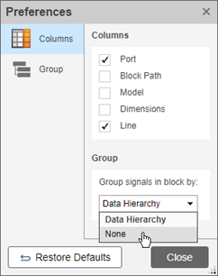
The Preferences dialog box. In the Columns tab, you can select whether or not to display the Port, Block Path, Model, Dimensions, and Line signal properties. In the Group tab, you can choose to group signals by Data Hierarchy or None.

 Functionality being removed or changed

Execution Order display for a selected task no longer highlights virtual blocks and signal lines

Behavior change

When you determine the execution order for a selected task, the virtual blocks and the signal lines are no longer highlighted. For more information, see Control and Display Execution Order.

Execution Order pane displays blocks with different types of constant sample times in separate tasks

Behavior change

The Execution Order pane displays blocks with different types of constant sample times in separate tasks. For example, Simulink blocks with constant sample times [Inf 0] and [Inf Inf] are displayed in two separate tasks indicated by unique Task ID values. For more information about constant sample times, see Constant Sample Time. For more information about execution order, see Control and Display Execution Order.

Component-Based Modeling

Override Model block simulation modes without dirtying parent models

To override the simulation modes of the Model blocks in a model hierarchy without dirtying their parent models:

  1. Configure the top model to simulate in normal mode.

  2. Specify how to override the Model block simulation modes using the new ModelReferenceSimulationModeOverride model parameter.

    • none (default) — Use the simulation modes specified by the Model blocks.

    • all-normal — Use normal mode for all Model blocks.

    • all-accelerator — Use accelerator mode for all Model blocks.

    • specified-models-to-normal — Use normal mode for the Model blocks that reference the specified models.

    • specified-blocks-to-normal — Use normal mode for the specified Model blocks.

  3. To override the simulation modes for specified models or Model blocks, get the model names and block paths using the new pathsToReferencedModel function.

  4. Specify the models or blocks using the new ModelReferenceSimulationModeOverrideScope model parameter.

The override is in effect during each of the simulation phases, including model compilation.

Model blocks that reference protected models do not support simulation mode overrides.

For an example, see Override Model Reference Simulation Modes.

Input bus element ports of subsystems support element specification without additional blocks or bus objects

Starting in R2023b, when you have at least one In Bus Element block that represents an input port of a subsystem, you can:

  • Specify properties of elements at that input bus element port without a block that selects the element or a Simulink.Bus object.

  • Add elements to that input bus element port without adding blocks or specifying a Simulink.Bus object.

Previously, only In Bus Element blocks at model interfaces supported this functionality.

For example, suppose a subsystem receives a bus that contains two elements. An In Bus Element block in the subsystem selects one of these elements. You can specify the properties of the elements regardless of whether an In Bus Element block selects them.
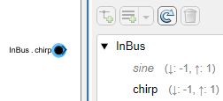
Both elements specify nondefault properties.

For another example, suppose you want to define the interface of a subsystem saved in a subsystem file. An In Bus Element block in the subsystem selects an element from the corresponding port. You can add elements to the port without adding blocks or specifying a Simulink.Bus object.
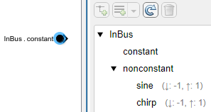
The port contains the selected element and a nested bus, which has three elements with nondefault properties. The nested bus and its elements are not selected by an In Bus Element block.

You can define the interface of the subsystem without cluttering the block diagram with unnecessary blocks. When you reference the subsystem file using a Subsystem Reference block, the hierarchy and properties of the input bus must match the definition at the corresponding port.

To add elements to an input bus without adding blocks to the block diagram:

  1. Double-click the In Bus Element block, or open the Property Inspector and select the block.

  2. In the dialog box or Property Inspector, select the element that you want to contain a new element.

  3. Click the Add element button arrow. Then, select Add element without block.

    The new element is nested under the selected element. The block diagram is unchanged.

To programmatically add elements to the input bus without adding blocks to the block diagram, use the Simulink.Bus.addElementToPort function.

Implicit fixed-step solvers support Simscape and Descriptor State Space blocks inside conditionally executed subsystems

The implicit fixed-step solvers ode1be and ode14x support simulating models with conditionally executed subsystems that contain implicit systems. For example, you can now use an implicit fixed-step solver to simulate a model that contains an enabled subsystem or action subsystem that uses Simscape blocks. In prior releases, the software issued an error in this situation.

Implicit systems have continuous states and require an implicit solver. Because triggered subsystems and function-call subsystems do not support continuous states, these types of subsystems cannot contain implicit systems and are not affected by this change.

Promote content preview of active choice to Variant Subsystem automatically and directly navigate to the active variant

Starting in R2023b, Simulink promotes the content preview of the active choice of the Variant Subsystem automatically. Additionally, you can navigate directly inside the active variant by double clicking on the Variant Subsystem block. Previously, to determine and open the active choice, you had to write a script in the openfcn callback of the Variant Subsystemblock.

Activate Variant Parameters from Variant Manager for Simulink support package

When you activate a variant configuration from Variant Manager, the operation activates any variant parameters present in the base workspace or data dictionaries that are associated with the active model components in the model hierarchy.

In the Variant Parameters tab, active variant parameters appear highlighted and inactive variant parameters are grayed out. Point to variant parameters to display a tooltip that shows any additional information related to the activation status. You can find the usage of variant control variables by variant parameters in the model hierarchy table. Right-click the variable in the Control Variables table and select Show usage or Hide usage.

For more information, see Create a Simple Variant Parameter Model.
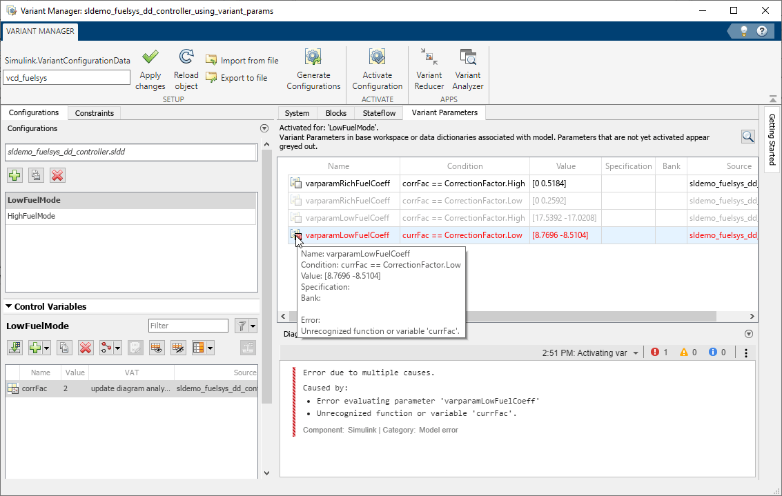
Variant Parameter tab in Variant Manager

Enhancements to the Variant Manager for Simulink support package

  • Remove Variant Subsystem Layer from Reduced Model

    Use the Remove Variant Subsystem Layer option in the Variant Reducer toolstrip to remove the outer layer of a Variant Subsystem block when only one of the choices of the variant subsystem remains active in the reduced model. Variant Reducer retains the active choice block and removes the Variant Subsystem block in the reduced model. The option is enabled by default. See Steps to Reduce Variant Model.

    Variant reducer toolstrip shows the Remove Variant Subsystem Layer option

    In this example, after reducing the model for the Nonlinear Controller configuration, the reduced model retains the Nonlinear Controller subsystem and the Controller variant subsystem is removed.

    Reduced model after removing the Variant Subsystem outer layer

  • Exclude Model Files During Variant Reduction

    The Files to exclude option in Variant Reducer now supports specifying Simulink model files (*.slx, *.mdl) to exclude when reducing a model. Previously, the option supported only data files (*.sldd, *.mat).

    For more information, see Steps to Reduce Variant Model.

  • Get Name of Referenced Component Configuration

    Simulink.VariantConfigurationData has a new method, getComponentConfigurationName, that allows you to get the name of the configuration used by a referenced component in a top-model configuration. For example,

    modelName = 'slexVariantManagement';
    openExample(modelName);
    vcd = Simulink.VariantManager.getConfigurationData(modelName);
    vcd.getComponentConfigurationName(ConfigurationName='LinExterHighFid',...
    ComponentName='slexVariantManagementExternalPlantMdlRef');

New edit-time filter functions to find Variant Subsystem blocks

Simulink provides these built-in match filter functions that you can use at edit time when searching models using find_system, find_mdlrefs, and Simulink.FindOptions.

  • Simulink.match.legacy.filterOutCodeInactiveVariantSubsystemChoices — Include Variant Subsystem block choices that are active in simulation or part of generated code when searching a model.

  • Simulink.match.legacy.filterOutInactiveVariantSubsystemChoices — Exclude inactive Variant Subsystem block choices when searching a model.

For more information, see MatchFilter.

Add multiple images to the block mask icon and package them with the model

Starting in R2023b, you can:

  • Add multiple images to the block mask icon using multiple image commands.

  • Package the images with the model using the option Save image files with model.
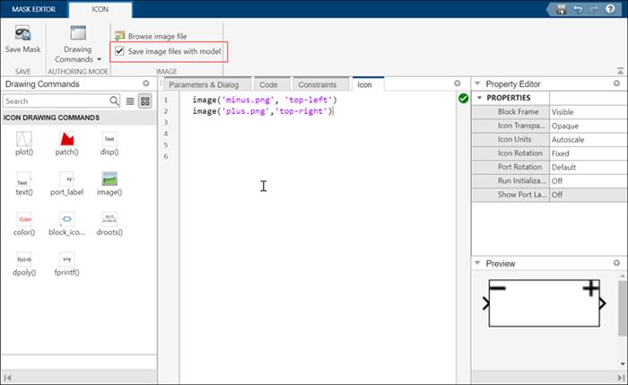
save image with model

Improved performance of models with several Subsystem Reference instances

Previously, when you modified and saved a Subsystem Reference block diagram, the changes propagated to the subsystem file and all the Subsystem Reference instances. Starting in R2023b, to optimize the performance of models, when you modify and save a Subsystem Reference block diagram the changes propagate to the subsystem file and only the visible Subsystem Reference instances. For more information, see Edit and Save Referenced Subsystem.

Trigger an aperiodic partition with multiple events in the Schedule Editor

In the Schedule Editor, you can trigger an aperiodic partition to execute by binding it to a Schedule Event. Starting in R2023b, you can bind multiple events to a single aperiodic partition.

Protected models can support external mode simulation

Starting in R2023b, when a protected model creator specifies that a protected model supports C code generation, the protected model also supports external mode simulation.

For more information about using protected models, see Reference Protected Models from Third Parties.

Support model workspace and mask workspace for variant blocks with startup activation time

Starting in R2023b, you can use mask and model workspace simulate and generate code for variant blocks with startup activation time. With model workspace support, you can have multiple instances of model blocks using variant control parameters as model arguments.

Match ports of variant choices to Variant Subsystem block interface

Starting in R2023b, you can detect inconsistencies and match the interface of the variant choices of the Variant Subsystem block. To enable this, turn off the Allow flexible interface block parameter. If the ports of the choice blocks do not match with the Variant Subsystem block you can either fix the interface by matching the ports, or turn on the Allow flexible interface parameter through the fix-it options reported.

Enhancements to Variant Subsystem block

Starting in R2023b, you can:

  • Display names of the newly created blocks and ports inside a Variant Subsystem block by default. Previously, to display the names of blocks and ports, you had to right-click on the block or port and navigate to Format > Show Block Name > On.

  • Set the name of the variant control label to the name of the variant choice for a newly created Variant Subsystem block in label mode.

  • Delete variant choices permanently in the Variant Subsystem block from the table in the Block Parameters dialog. To delete a choice, select the choice, and click the new delete icon. Previously, to delete a choice you had navigate inside the Variant Subsystem block and delete the choice.

Upgrade advisor check for export-function models

Starting in R2023b, you can check if the model settings to create an export-function model are satisfied. For more information, see Designate Model as Export-Function Model and Satisfy Export-Function Model Requirements. For more information about this check, see Check if the model settings to create an export-function model are satisfied.

 Functionality being removed or changed

convertToVariant, convertToVariantAssemblySubsystem, and variantLegend methods move to Simulink.VariantUtils class

Warns

The convertToVariant, convertToVariantAssemblySubsystem, and variantLegend methods will be removed from the Simulink.VariantManager class in a future release. The method calls continue to work with a warning.

Starting in R2023b, you can access these methods from the new Simulink.VariantUtils class. The convertToVariant method has been renamed to convertToVariantSubsystem in this class.

Simulink.Variant object renamed

Still runs

The Simulink.Variant object has been renamed to Simulink.VariantExpression. Using Simulink.Variant is not recommended and will be removed in a future release.

Invalid root Inport/Outport block connection diagnostic will be removed

Still runs

The Invalid root Inport/Outport block connection diagnostic configuration parameter will be removed and replaced with a Model Advisor check in a future release.

Extraneous discrete derivative signals diagnostic will be removed

Still runs

The Extraneous discrete derivative signals diagnostic configuration parameter will be removed in a future release. Use the Solver Profiler instead.

Change in default behavior of Simulink.VariantManager.reduceModel method

Behavior change

When you reduce a model that contains a VariantSubsystem block using the reduceModel method and if only one choice of the Variant Subsystem remains active after reduction, then the method removes the outer layer of the VariantSubsystem block and moves the block that represents the active choice to the top level in the reduced model. The RemoveVariantSubsystemLayer argument enables this behavior and its value is set to true by default.

New code generation requirement for model reference hierarchies that use fixed-step zero-crossing detection

Behavior change

When you generate code for a model reference hierarchy using Simulink Coder or Embedded Coder, the value of the Enable zero-crossing detection for fixed-step simulation parameter must be the same for the top model and all referenced models in the hierarchy.

Software issues warning for models with no continuous states that have fixed-step zero-crossing detection enabled

Behavior change

Since fixed-step zero-crossing detection became available in R2022a, the software has issued an error when a model enables fixed-step zero-crossing detection but does not contain any continuous states. Starting in R2023b, the software issues a warning instead to support code generation for model reference hierarchies that use fixed-step zero-crossing detection and have one or more models that do not contain continuous states. This change also provides improved support for configuration references for both simulation and code generation workflows.

Fixed-step zero-crossing detection improves the accuracy of simulation results by compensating continuous state values when discontinuities occur during simulation. Enable fixed-step zero-crossing detection for a model that does not have continuous states only when required for code generation. Enabling fixed-step zero-crossing detection for simulation of a model that has no continuous states might affect simulation performance.

lcc-win64 compiler will be removed

Warns

The lcc-win64 compiler will be removed in a future release. For information about supported compilers, see Supported and Compatible Compilers - Windows.

Project and File Management

Source Control API: Interact with Git source control programmatically

You can now programmatically interact with source control.

  • Clone a Git repository using the gitclone function.

  • Create a Git repository object using the gitrepo function.

  • Initialize a Git repository using the gitinit function.

  • Create, delete, and switch branches using the createBranch, deleteBranch, and switchBranch functions, respectively.

  • Add files, remove files, and commit changes to a Git repository using the add, rm, and commit functions, respectively.

  • Inspect the commit history in a Git repository using the log function.

  • Display the status of files in a local Git repository using the status function.

  • Fetch or pull new data from remote Git repositories using the fetch or pull functions, respectively.

  • Merge Git branches and revisions into the current branch using the merge function.

  • Publish your local changes to a remote Git repository using the push function.

Project API: Determine whether file belongs to a project

You can now programmatically determine whether a file or a folder belongs to a project by using the matlab.project.isFileInProject function.

Model Comparison: Improved reports for MATLAB Function blocks comparison

Model comparison publishable reports now use MATLAB Editor syntax highlighting for script parameters in MATLAB Function blocks. You can now more easily understand changes in MATLAB Function blocks. The report highlights and flags modified lines with the comparison icons , , and .

Model comparison report that shows a MATLAB Function block comparison.

Upgrade Advisor API: New property to disable backup file generation during model upgrade

By default, the upgradeadvisor function generates backup copies of models during the upgrade process. Starting in R2023b, you can disable the generation of backup files during a model upgrade using the EnableBackups property. For more information, see Programmatically Analyze and Upgrade Model.

Source Control in MATLAB Online: Perform source control operations using unified panel

In MATLAB Online, you can use the Source Control panel to see all active source control repositories, manage modified files, and perform source control operations.
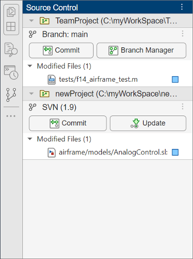
Source Control panel showing two repositories. The first repository is under Git source control and the second is under SVN source control.

To open the Source Control panel, use the Open more panels button (three-dot icon) in the sidebar.

MATLAB Online desktop with the Open more panels buttons circled in the left and bottom sidebars. The Open Panel dialog box shows the available panels.

Source Control in MATLAB Online: Expanded support for Git workflows

MATLAB Online now provides expanded support for Git workflows:

  • Adding and managing Git submodules

  • Sharing to GitHub®

  • Initializing Git repositories

  • Shallow cloning Git repositories

Projects in MATLAB Online: Added support for team collaboration workflows

Projects in MATLAB Online now provide support for the following team collaboration workflows:

  • Creating referenced projects from project folders

  • Adding source control to existing projects

  • Managing project labels and custom tasks using Project Settings

  • Displaying shadowed files on project startup

  • Upgrading projects using Project Upgrade

Project Examples: Identify and run tests in projects

This example shows how to use labels to identify tests in a project and how to create test suites from project test files interactively and programmatically. For large projects under source control, the example demonstrates how to run a subset of tests to reduce qualification runtime. For more information, see Identify and Run Tests in MATLAB Projects.

Design Evolution Manager in MATLAB Online: Active evolution automatically records changes made to project files

In previous releases in MATLAB Online, changes to project files were only synced to an evolution when you clicked Update Evolution. In R2023b, changes to project files are automatically recorded by the active evolution.

In MATLAB Online, when you finish making changes to project files in an evolution, you can lock the evolution to prevent further changes to project files in that evolution. You can still edit metadata, such as the name of the evolution or notes that you add to the evolution.

In MATLAB Online, if you make changes to project files when the Design Evolution Manager app is closed, you now have the option to save changes to the project in the evolution when you next open the app.

For example, in this evolution tree, the current files indicator marks the evolution whose files are currently open in the project, and the record indicator marks the active evolution. Project files in locked evolutions cannot be edited.

Evolution tree. The Baseline evolution is at the top and locked. Baseline has 2 child evolutions: Evolution 1 and Evolution 2. Evolution 2 is locked. Evolution 2 has a child evolution called Evolution 3. Evolution 3 is the active evolution and is the version of files currently open in the project.

Design Evolution Manager in MATLAB Online: Merging and arbitrary comparison workflows

The Design Evolution Manager app in MATLAB Online has improved comparison and merge workflows:

  • In previous releases, you could only compare evolutions that had a parent-child relationship. In R2023b, you can compare any two evolutions in the evolution tree.

  • You can now compare any two files in different evolutions, even if the files have different names.

  • You can use the integrated Comparison tool to merge differences from an evolution into the active evolution.

 Functionality being removed or changed

XML comparison type for visdiff function will be removed

Warns

The XML comparison type for the visdiff function will be removed in a future release. Overriding the default comparison type by specifying "xml" will not be supported in a future release. In R2023b, scripts that use visdiff(filename1,filename2,"xml") warn.

No compression when you save Simulink models

Behavior change

Starting in R2023b, to reduce the size of Git repositories that contains Simulink models, Simulink no longer applies compression during the save operation. For more information, see Set SLX Compression Level.

Getting parameters of the default block diagram is no longer supported

Errors

Starting in R2023b, getting parameters of the default block diagram is no longer supported. In R2023b, when parameter is the name of a block diagram parameter, scripts that use get_param(0,parameter) error.

Data Management

New section in the Simulink data dictionary containing architectural data

In R2023b, a new architectural data section is added to the Simulink data dictionary. This section of the dictionary stores shared definitions used in the Simulink and architecture model interfaces, such as port interfaces, data types, and system wide constants as well as their platform properties. You can manage architectural data with the Architectural Data Editor and the Simulink.dictionary.ArchitecturalData programmatic interfaces. This new architectural data section allows users to adhere to best practices for data management and it gives a seamless user experience by managing all architectural data in one editing tool.

Type Editor docked in model window

When you open the Type Editor from a model, the Type Editor is docked as a pane in the model window.
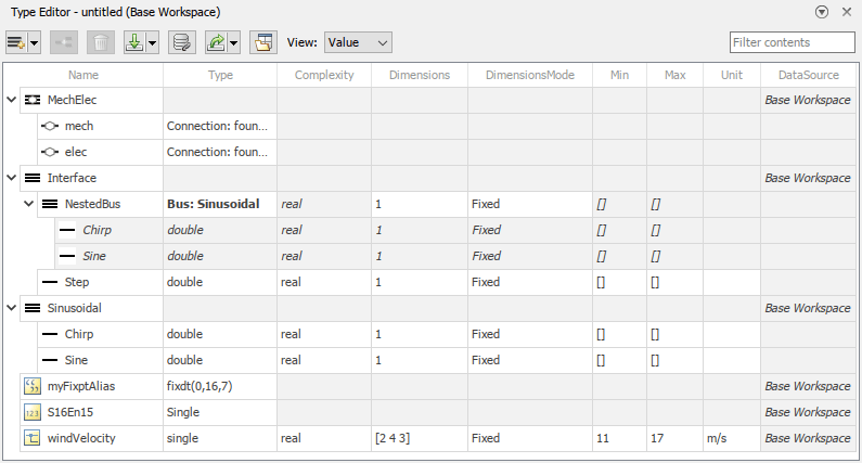
Docked Type Editor with simplified buttons and layout

This integration lets you view where a type is used in your model. For example, you can click a type in the docked Type Editor to highlight the blocks that use the type.
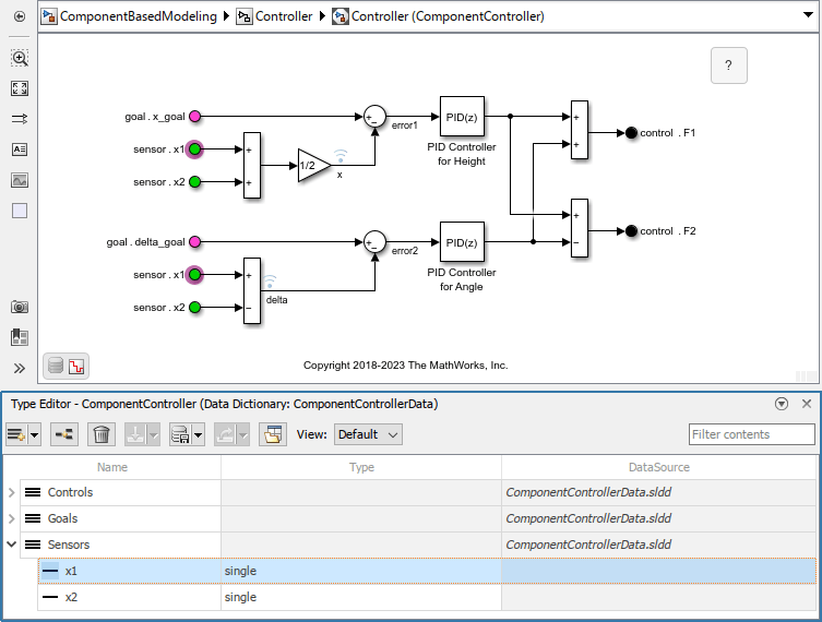
The In Bus Element blocks that select sensor.x1 are highlighted because the Type Editor has the corresponding x1 bus element object selected.

To open the Type Editor in a standalone window, click the Open standalone Type Editor button.

For more information, see Type Editor.

Simulink.Parameter object now supports strings

Simulink.Parameter objects now support string scalars as values. For example:

P1 = Simulink.Parameter("abc");
P2 = Simulink.Parameter;
P2.Value = 'xyz'; 

Signal Editor tool updates

The look and feel of the Signal Editor tool has changed. Changes include:

  • Signal Editor icons and layout have changed.
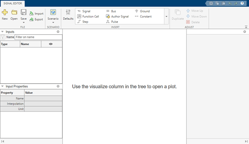
    Signal Editor tool default

    You can customize this layout by dragging and dropping panes and hiding panes.

  • Continue to add scenarios and signals as you did in releases prior to R2023b. To edit or view the plot of a signal, double-click the hide icon (Signal Editor eye for plotting). The Edit tab opens. Notice that signal properties are now on the right of the canvas.
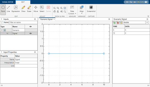
    Signal Editor tool hide

    To close the Edit tab and return to the Signal Editor tab, double-click the show icon (Signal Editor tool show).

  • To start drawing signals, double-click the hide icon Signal Editor eye for plotting. In the plot canvas, you can begin adding signal data points. Previously, you clicked Draw Signal to enter the drawing mode.

  • In the left side Inputs section, you can now select multiple items simultaneously and perform actions on them.
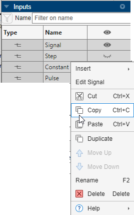
    Signal Editor multiple signal selections and right-click context menu

    For example, you can:

    • Select multiple signals and edit the input properties for multiple signals at the same time.

    • Create the same signal for multiple scenarios.

  • In the tabular editing pane, you can cut, copy, and paste with Excel spreadsheets.

  • These icons have changed.

    Action

    Old Icon

    New Icon

    Function Call

    Author Signal

    Duplicate

    Delete

    Insert row

    Delete row

    Replace signal data using MATLAB expression

    Erase

    Fit to view (Space)

    Data Cursors

    Align

Root Inport Mapper updates

The Root Inport Mapper tool Check Map Readiness menu has these changes:

  • The default behavior of the Check Map Readiness button now defaults to the last Check Map Readiness option selected.

  • When you click Apply to Model, the status now displays in the Status column of the Scenarios panel.

  • Option names and icons have changed.

    Old Option and IconNew Option and Icon

    Map All ()

    All Scenarios ()

    Map Selected ()

    Selected Scenarios ()

    Map Unconnected ()

    Unconnected Scenarios ()

    Map Failed ()

    Failed Scenarios ()

    Map Warned ()

    Scenarios with Warnings ()

Support for MDF format

The Signal Editor and Root Inport Mapper tools now support reading the MDF format with the Simulink.io.MDF reader class. The Simulink.io.MDF class requires a Vehicle Network Toolbox or Powertrain Blockset™ license.

For more information, see Import Custom File Type and Create Custom File Type for Import to Signal Editor.

Mismatched unit detection for model arguments

The software now checks for equivalent unit values when a model argument definition and value have units. At a component boundary, the software detects and reports a warning when these units are mismatched. For more information, see Mismatched Units Detected Between Model Argument Definition and Value.

Support for library dictionaries in Subsystem Reference

Subsystem Reference now supports using data dictionary attached to library blocks. When you add a library block to a subsystem file, the data dictionary attached to the library becomes available to the subsystem file. If you refer to the subsystem file from a model using a Subsystem Reference block, the library dictionary is available within the Subsystem Reference block boundary only.

 Functionality being removed or changed

More efficient check and error reporting behavior for data consistency check

Behavior change

Previously, when a model in a hierarchy was compiled during a model update, Simulink ran a data consistency check on the model if the model was configured to enforce data consistency (EnforceDataConsistency set to the default 'on'). In R2023b, these models are all checked for data consistency when the top model in the hierarchy compiles.

While there is no change in the errors that the consistency checker detects, you might see a change in how the errors are reported. Previously, you might only see a subset of consistency errors in the hierarchy if an error detected below the top model stopped the model update. In R2023b, when the top model compiles, the consistency check reports errors from multiple levels of the model hierarchy at the same time.

For more information on data consistency checks, see Data Consistency in Model Hierarchy.

Simulink.ValueType objects do not override description of parent

Behavior change

When you specify a Simulink.ValueType object as the data type of a Simulink.Signal, Simulink.Parameter, or Simulink.BusElement object, the value type object no longer overrides the description of the parent object.

Block Enhancements

Data Store Memory: Access scoped Data Store Memory blocks across the model hierarchy

Starting in R2023b, a subset of Simulink blocks from inside a referenced model can access the data stored in a Data Store Memory block defined at a higher level in the model hierarchy. These blocks include Data Store Read block, Data Store Write block, S-Function block, MATLAB Function block, MATLAB System block and Chart (Stateflow) block. To allow these blocks to access the data stored in the Data Store Memory block at a higher level in the model hierarchy:

  • Place a Data Store Memory block inside the referenced model. For more information about supported locations of the Data Store Memory block, see Description in Data Store Memory.

  • In the Data Store Memory block dialog box, select Data store reference.

  • On the Signal Attributes tab, specify the Data type, Dimensions and Signal type. When you select Data store reference, these options are not available: Inherit for Data type, -1 for Dimensions and auto for Signal type.

To configure a data source reference for code generation, see Code Generation for Data Store References (Simulink Coder).

Conditional display of the Sample time parameter in certain blocks

These blocks no longer display the Sample time parameter in the block parameters dialog box by default:

The Sample time parameter is visible in the block parameters dialog box only if you set the sample time to a value other the default (-1) either programmatically or in an existing model. For more information, see Blocks for Which Sample Time Is Not Recommended.

Signal Editor block updates

The Signal Editor block dialog box has these updates:

  • In the Signal properties section, the new Apply signal properties to all signals check box lets you apply the specified signal properties to all signals.

  • When you pause on the Active scenario parameter, a tooltip displays the Name property of the data set object. If the block is converted from a Signal Builder block using the signalBuilderToSignalEditor function, the Name property is the same as the Signal Builder block Group name.

Weighted Sample Time and Weighted Sample Time Math blocks update

The Weighted Sample Time and Weighted Sample Time Math blocks now support:

  • Additional output types

    • double

    • single

    • int8

    • uint8

    • int16

    • uint16

    • int32

    • uint32

    • int64

    • uint64

    • fixdt(1,16,0)

    • fixdt(1,16,20,0)

  • Fixed point as a new option to the Mode parameter, which enables the fixed-point parameters:

    • Signedness

    • Scaling

    • Word length

    • Slope

    • Bias

    • Data type override

signalBuilderToSignalEditor function update

The signalBuilderToSignalEditor function now supports virtual buses. If the original Signal Builder block contains a virtual bus output port, signalBuilderToSignalEditor returns a handle to a Subsystem that has a virtual bus output port.

Use the customizable Display block to model displays in real systems

Model displays in real systems, such as the odometer display in your car, using the customizable Display block.

The Display block connects to a signal in your model and displays its value during simulation. When you use the Display block in the Customizable Blocks library, you can customize the appearance of the block to look like a real display in your system.

  • Add a background image or choose a background color.

  • Add a foreground image.

  • Choose from a list of WYSIWYG (what you see is what you get) fonts that look the same on all platforms.

  • Change the font size.

  • Change the text color.

  • Change the text position within the block.

  • Make the text bold, italic, or underlined.

Use the Display block with other dashboard blocks to build an interactive dashboard of controls and indicators for your model.

For more information about the Display block, see Custom Display.

Open dashboard panel in new window

You can now open a dashboard panel in a new window. You can minimize and restore the new window containing the panel separately from the model window. From the panel window, you can run, pause, stop, and step through the simulation.

To open a dashboard panel in a new window, select the panel. In the Simulink Toolstrip, on the Panels tab, in the Manage section, click Open In New Window. Alternatively, select the panel and pause on the ellipsis that appears. In the action menu that expands, click the Open In New Window button .

Note

If a panel contains Dashboard Scope blocks, you cannot open the panel in a new window during simulation. To open the panel in a new window, stop the simulation.

If the panel has multiple tabs, the panel with all its tabs opens in a new window.

To return the panel to the model canvas, in the panel window toolstrip, click Open in canvas .

For more information about opening a panel in a new window, see Open Panel in New Window.

IC block row-major support update

The IC block now supports code generation for row-major array layout.

Permute Matrix block row-major support update

The Permute Matrix block now supports row-major algorithms and code generation for row-major array layout.

Enhancements to C Caller and C Function blocks and custom code integration

In R2023b, C Caller and C Function blocks and custom code integration have these enhancements.

  • When you integrate a custom code library, if you are using the MinGW® compiler as your MEX compiler, you only need to include the DLL (.dll) format of the library in the configuration for your model. Before R2023b, the software checked for both the .dll and the .lib format. If you are using Microsoft Visual C++® (MSVC) as your MEX compiler, you still need to include both formats. For more information on how to include libraries, see Libraries. For more information on selecting a MEX compiler, see Change Default Compiler.

  • C Caller and C Function blocks support the pointer to array type and aliases as function arguments and global variables. Variables of this type point to an entire array. This example shows how to declare variables of this type. In this example, ptr is a pointer to an array of five integers. The ptrType type is used to create ptr2, which is also a pointer to an array of five integers.

    int (*ptr)[5];
    
    typedef int (*ptrType)[5];
    ptrType ptr2;

  • Before R2023b, global and static variables in custom code retained their values between simulation runs, causing unexpected results. Starting in R2023b, global and static variables in custom code are reset between simulation runs.

  • Before R2023b, the software did not support calling custom C/C++ functions declared with static inline. Starting in R2023b, you can call static inline C/C++ functions in blocks with custom C/C++ code.

Constant block supports Simulink.ValueType object data type

Constant blocks now support Simulink.ValueType objects as data types. Each value type specified for a Constant block must have fixed dimensions because Constant blocks do not support variable-size signals.

When you specify a value type as the data type of a Constant block, the value type overrides the minimum and maximum specified by the block and the data type of the constant value. The value type validates the dimensions, complexity, and unit of the constant value. When these properties do not match, the software issues a warning or error.

For example, suppose a Constant block has these settings:

  • Constant value set to a Simulink.Parameter object with a unit of ft/s

  • Output data type set to a Simulink.ValueType object with a unit of m/s

During model compilation, the software issues a warning about the mismatched units. The Constant block uses ft/s as the unit.

For another example, suppose a Constant block has these settings:

  • Constant value set to [2 3]

  • Output data type set to a Simulink.ValueType object with dimensions of 1

During model compilation, the software issues an error about the mismatched dimensions. Mismatched complexity also results in an error.

The Constant block does not use the description of the value type.

For more information about value types, see Specify Common Set of Signal Properties as Value Type.

Bus Selector block dialog box redesigned

The Bus Selector block dialog box has a new, streamlined design with additional functionality.

  • In the Elements in the bus list, a green check mark icon appears next to selected output elements.

  • In the Elements in the bus list, when you pause on a selected output element, a parenthetical displays how many times the Bus Selector block selects that element.

  • Filtering supports regular expressions by default.

  • You can toggle between vertical and horizontal layouts.

By default, the dialog box opens in the new vertical layout, with the selected elements under the list of elements in the bus.
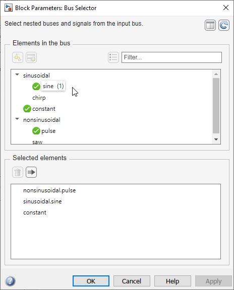
Bus Selector block dialog box with vertical layout

To view the elements in the bus and the selected elements side by side, click the Change layout button.

Bus Selector block dialog box with horizontal layout

The horizontal layout more closely mimics the previous Bus Selector block dialog box design.

The previous functionality remains.

  • Filter the elements in the bus by name with or without regular expression — Enter the search term in the Filter box.

  • Show filtered results as a flat list — Click the Show filtered results as a flat list button.

  • Find source of elements in the bus — Click the Highlight source blocks button.

  • Refresh list of elements in the bus — Click the Refresh button.

  • Select output elements — Select the desired output elements from the Elements in the bus list. Then, click the Select elements button (vertical layout) or the Select elements button (horizontal layout).

  • Move selected elements up or down — Drag elements in the Selected elements list to a different position in the list.

  • Remove selected elements — Select the elements to remove from the Selected elements list. Then, click the Remove button.

  • Output selected elements as a virtual bus — Click the Output as virtual bus button.

Parameter Writer block supports invisible masked subsystem parameters

A Parameter Writer block can now write to a masked subsystem parameter that is enabled regardless of whether the mask dialog box displays the parameter.

Tunability of mask parameters that are modified or created in mask initialization is retained in the generated code

Before R2023b, if a model contained blocks with mask initialization commands that modified a mask dialog parameter or created a new variable in the mask initialization, and if that parameter or variable is referenced in a child block, the values of the mask parameter or variable were in-lined in the generated code. The parameters were not tunable even if they referred to a workspace variable.

Starting in R2023b, expressions corresponding to mask parameters referenced in the child block now appear in the generated code even if the parameters are created in mask the initialization section of the top-level mask thus retaining tunability. The tunability of these parameters is retained only if the mask initialization code is created using a mask callback file and the parameter value is defined in the specified format. See Preserve Tunability of Parameters That Are Modified or Created in Mask Initialization for more information.

Preserve tunability of mask parameters whose values are referencing a subarray

When the value of a mask parameter is a MATLAB array, and you set one of the array elements to the value of an underlying child block parameter, the tunability of the mask parameter is preserved in the generated code.

For example, consider a masked subsystem containing a Gain block as a child block. The masked subsystem has a tunable parameter named customGain whose value is set to a workspace variable baseVar. The value of baseVar is a MATLAB array. The value of Gain parameter in the Gain block is set to an element of customGain using the subscript operator. In this scenario, tunability of customGain is preserved because the variable baseVar is retained in the generated code.
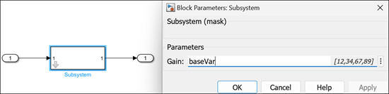
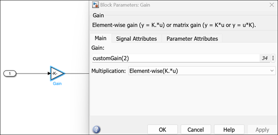
Masked subsystem block referring subarray

Child block referring the tunable parameter

The generated code is:

Array elements listed in the data file of the generated code

Model step function containing the expression

Observe that the generated code contains the expression for the tunable parameter.

Improve tunability for mask enumeration parameters popup and radio button

Starting in R2023b, you can tune the mask radio button parameter by providing a list of options for simulation time tunability or an enumeration class for code generation tunability.

  • Use List of options to create options for the radio button with display names and the values. You can enter numeric or string values as options.

  • Create a new enumeration class with name, member names and values or reference an external enumeration class derived from Simulink.IntEnumType or Simulink.Mask.EnumerationBase. You can only associate numerical values to the radio button using an enumeration class.

  • Associate a workspace variable with a mask radio button parameter.

See Tune Mask Enumeration Parameters - Popup and Radio Button for more information.
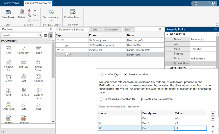
tunable radio button

Improvements to Graphical Icon Editor

Starting in R2023b, you can:

  • Render multiple variations of the same block icon using layers. Each variation is visible based on conditions on the block parameters. The variations are saved in a single file. For example, you may want to increase the number of switch ports based on a block parameter. Use layers to create multiple variations of the block icon for each scenario. See Add Dynamic Behavior to Masked Icons for more information.
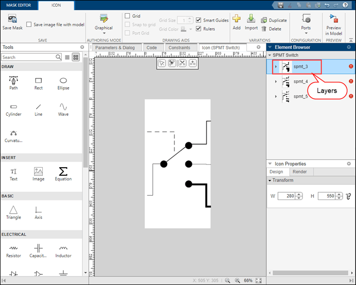
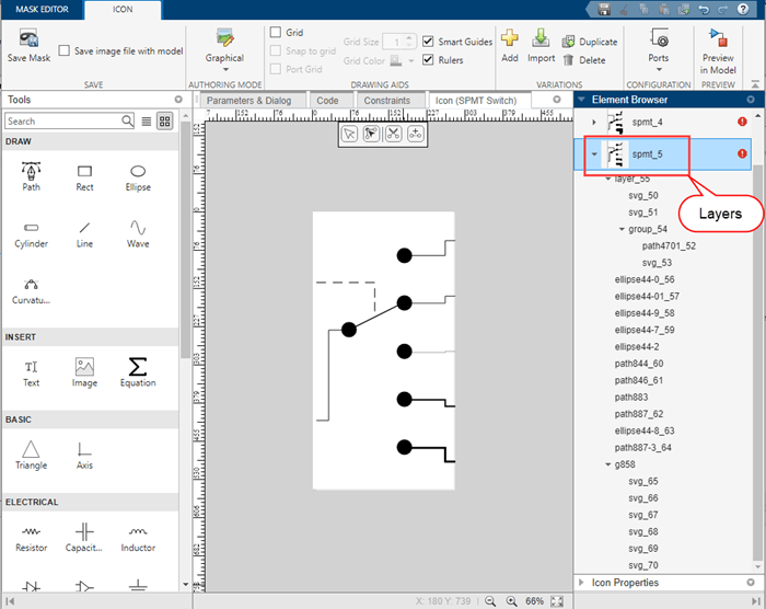
    layers

    variation of the icon

  • Package icon image files with the model using the option Save image files with model in the Graphical Icon Editor.
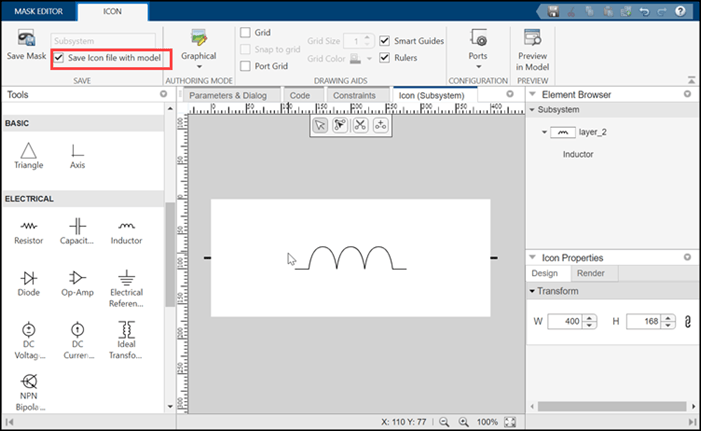
    save image

  • Select arrow heads based on type, fill, and size. Previously you had to choose the arrowhead style from a long list of 250 styles. You can now choose from a drop-down list, toggle to fill the arrowhead, and select the size of the arrowhead.
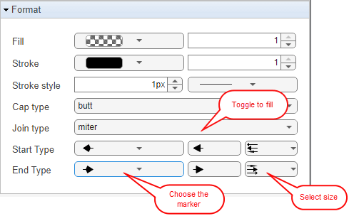
    arrow head choice

  • Easily access canvas properties and element properties. The options are listed based on the icon and element context. For the icon, you have options to set the frame of the icon and rotate or resize the icon. For each element in the icon, you can rotate, resize, and set the stroke of the element. Previously, these options were under Simulink properties in the toolstrip. Now these options are available in the Icon Properties and Element Properties section.
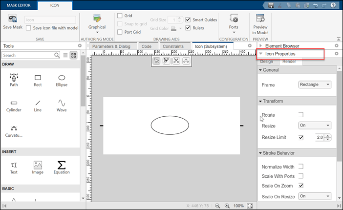
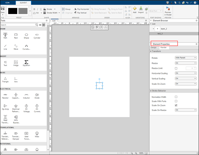
    icon properties

    element properties

  • Use the option Port Grid to align the elements of the canvas to ports.
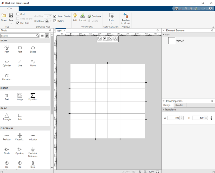
    port grid

  • Find port styling information for Simscape blocks in the Graphical Icon Editor.
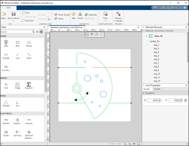
    port styling

Neighborhood Processing Subsystem block supports one-dimensional array input

Starting in R2023b, the Neighborhood Processing Subsystem block supports using one-dimensional arrays as input matrices. Use the Neighborhood Processing Subsystem block to divide a sequence of data into sections and process each section separately.

Customize System object icon using Mask Editor

You can now use the Mask Editor to create and edit the mask icon of a MATLAB System block. The Mask Editor helps you to customize a block icon with descriptive text, images, equations, and graphics using the Graphical Icon Editor or mask drawing commands and save time in writing code. When you use the Mask Editor, all mask definitions are stored in an auxiliary XML file resulting in faster loading of the System object. For more information on icon customization using Mask Editor, see Customize MATLAB System Icon and Dialog Box Using Mask Editor.

If you previously customized the mask of a MATLAB System block using the getIconImpl function in a MATLAB System class file, then you can migrate these mask definitions to an auxiliary XML file. Launch the Mask Editor of the MATLAB System block and save the mask. You will get a message:

  • Click Save to save the existing and new dialog and icon customizations to a new XML file. This removes all the dialog and icon customization related functions from the existing MATLAB System class file.

  • Click Cancel to continue using the dialog and icon customizations from the MATLAB System class file. Any customizations done using the graphical interface are discarded.
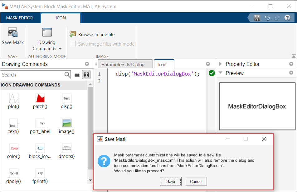
View of MATLAB System Block Mask Editor. The left pane displays the Icon drawing commands. The middle pane displays when a MATLAB System mask icon is modified and saved, a warning message is displayed.

Faster loading of System object blocks

Loading of MATLAB System objects into Simulink shows improved performance as the mask definitions of the System object blocks are now saved in an auxiliary XML file.

For example, if you load ten MATLAB System object blocks, performance in R2023b is approximately 2.5x faster than in R2023a.

The approximate reporting times are:

R2023b: 3.5 s

R2023a: 9 s

The reporting was timed on a Windows 10, AMD EPYC 74F3™ 24-Core Processor @ 3.19 GHz test system by calling the tic and toc functions for ten MATLAB System object blocks: TPC Decoder, TPC Encoder, Timer Block, Wavetable Synthesizer, Audio Oscillator, Octave Filter Bank, OFDM Modulator, Viterbi Decoder, Linear Equalizer, and Decision Feedback Equalizer.

You can get this performance gain for your System objects by migrating the mask definition of the System object block from the MATLAB System class file to an auxiliary XML file. For more information on migrating, see Migrate Existing Icon and Dialog Box Customizations to Mask Editor on Customize MATLAB System Icon and Dialog Box Using Mask Editor.

From Spreadsheet block update

The From Spreadsheet block now searches for the spreadsheet file within the current folder if it cannot find the spreadsheet file in the full path provided. This change enables Simulink Compiler standalone executables containing From Spreadsheet blocks to find spreadsheet files. In previous releases, the From Spreadsheet block did not look for spreadsheet files in current folders.

Code generation support for FMU Import block

The FMU Import block now supports code generation for FMI 1.0 and FMI 2.0.

Python Importer now supports Python functions specified within Python classes

You can now use Python Importer wizard to import Python functions that are defined within Python classes. Python Importer generates a MATLAB System object for each of the selected functions and creates a block library containing MATLAB System blocks that implement each of the generated System object in Simulink. When a class constructor method is specified with the Python class, the Python Importer defines the class constructor arguments as non-tunable properties of the generated System object. The properties appear as non-tunable parameters of the corresponding MATLAB System block in Simulink.

For example, consider the following Python class:

class room:
    
    def __init__(self, length, breadth, height):
        self.length = length
        self.breadth = breadth
        self.height = height
    
    def volume(self):
        result = self.length * self.breadth * self.height
        return result

    def wallarea(self):
        result = 2 *(self.length * height + self.breadth * height)
        return result
Python Importer enables you to import the functions volume and wallarea. You can also set the port and parameter specifications during import. In this example, length, breadth, and height specified in the class constructor are imported as parameters.
Python Importer window to specify parameters and port specifications

The Python Importer generates a block library with a MATLAB System block for each of the imported functions. The attributes of the class are defined as non-tunable parameters of the block. In this example, length, breadth, and height can be set in the Block Parameters dialog.
Generated Simulink block library and parameters

FMI 3.0 support for FMU Import block

Starting in R2023b, the FMU Import block supports the following FMI 3.0 features:

  • Introduction of new integer and float data types.

  • Native support for vectors and matrices.

  • Event mode support for co-simulation mode.

  • Binary data type support.

Enumeration data type support for FMU Import block

Starting in R2023b, the FMU Import block supports Enumerated data type for block input and output. You can directly connect enumeration signals to FMU Import block without conversion to int32 data type. You can also use the FMU Import dialog to customize the names of enumeration objects.

Discrete input value changes in Model Exchange FMU triggers event mode

In R2023b, the FMU Import block detects discrete input value changes for Model Exchange FMU and triggers event iteration.

Directly launch external debugger for debugging S-function from Simulink

You can now directly launch an external debugger for debugging S-Function and S-Function Builder blocks from Simulink without manually configuring the external debugger to connect to Simulink. To launch the external debugger, go to the Debug tab in Simulink and select Set Breakpoints in Custom Code option.

Launch external debugger from the debug tab of Simulink using Set Breakpoints in Custom Code option from drop-down

The Select Entities to Debug dialog box list the entities that can be debugged. The custom C/C++ code defined for a model in the Simulation Target pane of the Model Configuration Parameters dialog box is listed under Model Custom Code and the S-function and S-Function Builder blocks are listed under S-Function Blocks. Select the entities that you want to debug and move them to Selected Entities.
Dialog box that lists entities that can e debugged

Click Open to launch the external debugger.

Rate Limiter Dynamic simulates more accurately for initial input signal

Starting in R2023b, the Rate Limiter Dynamic block simulates more accurately for the initial input signal. If the expected output sample is nonzero, you will now get the expected value based on the initial condition. In releases prior to R2023b, initial output samples were always 0.

 Functionality being removed or changed

New warning identifies Derivative blocks with inputs that do not have continuous sample time

Warns

A new warning identifies Derivative blocks that have input signals with discrete or fixed-in-minor sample time. When the input to a Derivative block does not have continuous sample time, the block might produce incorrect or unexpected results. The software issues a warning at compile time for each block that requires attention.

To resolve the warning, you can:

  • Modify the model so that the input signal has continuous sample time.

  • Solve the system by integrating instead of differentiating by using block that integrate, such as the Integrator block, instead.

  • Implement the derivative using another block, such as the Transfer Fcn block or the Discrete Derivative block.

For more information, see Derivative.

Connection to Hardware

Support to download Android support package on Linux operating system

Starting R2023b, you can now download the Simulink Support Package for Android Devices on devices with the Linux operating system.

Capture JPEG images from ArduCam 2 megapixel Mini Module Camera Shield with OV2640 sensor

This release introduces the OV2640 Camera Sensor block, which you can use to capture JPEG images from the ArduCam 2 megapixel Mini Module Camera Shield with an OV2640 sensor. You can also specify the resolution of the JPEG image that the block outputs.

Support for handling hardware interrupts from ADC and PWM peripherals and event systems on Arduino SAMD hardware

The Simulink Support Package for Arduino Hardware now supports handling hardware interrupts generated by the ADC and PWM peripherals for the SAMD family of Arduino hardware. Earlier releases supported handling of hardware interrupts only from external pins. This release also adds support for event system (EVSYS) that allows autonomous, low-latency, and configurable communication between the peripherals.

  • Hardware Interrupt — Use this block to trigger a downstream function-call subsystem from an interrupt service routine.

  • PWM — Use this block to generate a square wave on the specified output pin of the Arduino SAMD hardware.

  • Analog Input — Use this block to read the ADC register value at the specified pin of the Arduino SAMD hardware.

You can access these new blocks from the Advanced > SAMD library.

Send and receive data from HTTP server using HTTP Client block on Raspberry Pi hardware

This release introduces the HTTP Client block that you can use to send and receive data from the remote server using the HTTP protocol.

Support for external mode for Raspberry Pi — Robot Operating System (ROS)

The Raspberry Pi Blockset now supports using the external mode (Monitor and Tune) workflow to tune parameters and monitor a Simulink generated ROS node within a ROS network.

Support for secure MQTT communication between server and client on Raspberry Pi hardware

The Raspberry Pi Blockset now supports establishing a secure MQTT connection between the server and a client using a certificate-based authentication. You can now configure MQTT parameters such as port number and specify an SSL certificate to authenticate the connection to the server.

MATLAB Function Blocks

Support for unbounded arrays

MATLAB Function blocks now support unbounded arrays for output and input variables. To specify unbounded output variables, select the Variable size property for the variable and set the dimension in Size to Inf. Input variables inherit their size. See Unbounded Variable-Size Signals, Declare Variable-Size MATLAB Function Block Variables, and Specify Size of MATLAB Function Block Variables.

coder.mustBeConst: Validate that value is compile-time constant

Starting in R2023b, you can use the coder.mustBeConst validator inside an arguments block to validate that the value of a function argument is a compile-time constant.

Code generation for more toolbox functions

In R2023b, you can generate code for many additional toolbox functions and objects. For a list of all functions and objects that are supported for code generation, see:

These are links to the release notes of some toolboxes that added code generation support in R2023b:

Computer Vision Toolbox

See Generate C and C++ Code Using MATLAB Coder: Support for functions (Computer Vision Toolbox).

Image Processing Toolbox

See C Code Generation: Generate code from additional functions using MATLAB Coder (Image Processing Toolbox).

ROS Toolbox

See C++ Code Generation Support Enhancement for ROS 2: Deploy ROS nodes to target hardware using MATLAB Coder (ROS Toolbox).

Signal Processing Toolbox

See C/C++ Code Generation Support: Code generation for spectral analysis and signal modeling (Signal Processing Toolbox).

Statistics and Machine Learning Toolbox

See:

Modeling Guidelines

Guideline for check safety-related diagnostic settings for Stateflow

These high-integrity system modeling guidelines have been modified or removed.

Modeling GuidelinesDescription
hisl_0012: Usage of conditionally executed subsystemsRemoved
hisl_0024: Inport interface definitionNote includes information about capturing reusable specifications as a Simulink.ValueType object and specifying the data type for the In Bus Element and Out Bus Element blocks.
hisl_0039: Configuration Parameters > Code Generation > Interface

Removed support for model parameter support: absolute time from the check analysis.

hisl_0044: Configuration Parameters > Diagnostics > Sample TimeRemoved support for configuration parameter single task data transfer from the check analysis.
hisl_0063: Length of user-defined object names to improve MISRA C:2012 complianceIncludes information for using a Service Interface configuration.

Guidelines about the creation of data copies for component deployment

Starting in R2023b, the information in these code generation modeling guidelines is modified or removed.

Modeling GuidelineDescription
cgsl_0204: Vector and bus signals crossing into atomic subsystems or Model blocksRemoved information about the creation of data copies.
cgsl_0402: Signal interfaces for component deploymentAdded information about the creation of data copies when the signal type is In Bus Element or Out Bus Element.

R2023a

New Features, Bug Fixes, Compatibility Considerations

Open Simulink models with invalid names

You can now open a model even when the file does not have a valid name, for example, mymodel (1).slx. Simulink opens the model and assigns a valid name. To rename or save changes to the newly named model, click Save. For more information, see Choose Valid Model File Names.

Enhancements to suppression manager user interface

You can now add inline comments to suppressed warnings. You can also filter diagnostic messages, suppression location, and comments using a global filter. The look and feel of the suppression manager is also enhanced.
suppression manager

For more information, see Suppress Diagnostics

 Functionality being removed or changed

Removed warning and corrected keyboard shortcut actions for comment-out and comment-through operations

Behavior change

The comment-out and comment-through workflows have been updated:

  • Commenting out or commenting through a group of blocks does not issue a warning for the blocks that do not support these operations.

    • If you select a combination of blocks that support and unsupport commenting out or commenting through operations, Simulink comments only the supported blocks. The unsupported blocks are silently skipped.
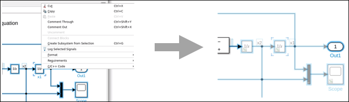
      Supported and unsupported blocks after comment out or comment through operation

    • If all the blocks that you select do not support commenting, the Comment Out and Comment Through options are disabled.

    • If the blocks that you select are already commented out, the Comment Out option is disabled.

    • If the blocks that you select are already commented through, the Comment Through option is disabled.

    In previous releases, these actions issued a warning for unsupported blocks and continued to comment the supported blocks.

  • The keyboard shortcuts Ctrl+Shift+X and Ctrl+Shift+Y failed to uncomment a group of commented-out and commented-through blocks if the selection included one or more unsupported blocks. These shortcuts now work properly.

For models created before R2010b, Simulink no longer renames blocks that only differ in white space type

Behavior change

In R2023a, Simulink no longer renames blocks that only differ by the type of the white space. The same subsystem cannot contain two different blocks that only differ in the white space type, for example and . This was only possible for models created before R2010b.

For models created in R2010a and earlier, Simulink warns when attempting to load the blocks that only differ in white space type. Rename the block in a previous release and save the model.

Simulation Analysis and Performance

Step simulation block by block using new options in the Simulink Editor

In previous releases, when you simulated a model that contained signal breakpoints, the simulation paused at the end of the major time step in which the condition for the signal breakpoint was met. Starting in R2023a, by default, the simulation pauses within the time step as soon as the condition is met. Once the simulation pauses within the time step, new stepping buttons on the Debug tab of the Simulink Toolstrip become active and allow you to step through the simulation execution one block at a time. As you step through a simulation block by block, you can use port value labels to view signal values in the block diagram.

In addition to the enhanced capabilities for signal breakpoints, you can now add zero-crossing and Inf or Nan value model breakpoints using the Simulink Toolstrip.

For more information about the new stepping and breakpoint options, see Breakpoints List.

These additions replace the standalone Simulink Debugger. The Simulink debugging programmatic interface remains unchanged for programmatic simulation debugging.

Add breakpoints and access help from the Breakpoints List

The Breakpoints List has two new buttons:

  • To add a signal breakpoint from the Breakpoints List, select a signal then click Add Breakpoint .

  • To access documentation, click Help .

In addition to the new buttons, you can use the new Pause within time step option to control whether the simulation pauses within a time step as soon as the condition for a breakpoint is met or pauses at the end of that time step. For more information, see Breakpoints List.

Performance improvement for simulations with back stepping enabled

Enabling stepping back in simulation has a smaller effect on simulation performance. To support stepping back in simulation, the software captures simulation snapshots, which adds overhead and can slow simulation. The performance improvement for simulations with stepping back enabled varies between models, with smaller improvements for models that use certain blocks and features, including:

  • Referenced models configured to simulate in accelerator mode

  • Simscape blocks

  • S-functions that implement custom methods for saving and restoring the S-function operating point

You can assess the performance improvement for a model by running equivalent simulations of the model in R2022b and R2023a with back stepping enabled and checking the execution time in the simulation metadata. For example, to assess the performance improvement for the model slexAircraftExample, follow these steps using R2022b and then R2023a:

  1. Open the model.

    openExample(...
        "simulink_aerospace/AircraftLongitudinalFlightControlExample",...
        supportingFile="slexAircraftExample")
  2. To capture timing information in the simulation metadata, including the time spent in the execution phase of the simulation, check that the Single simulation output parameter is enabled.

    In the Simulink Toolstrip, on the Modeling tab, click Model Settings. On the Data Import/Export pane, select Single simulation output.

  3. Enable stepping back.

    On the Simulation tab, click Step Back. In the Simulation Stepping Options dialog box, select Enable stepping back.

  4. In the Simulation Stepping Options dialog box, check that the Maximum number of saved back steps and Interval between stored back steps parameters both use the default value of 10. Then, click OK.

  5. Use the same start and stop times for the simulation in R2022b and R2023a. For this simulation, use a stop time of 1000 seconds.

    On the Simulation tab, in the Stop time field, enter 1000.

  6. To run the simulation, on the Simulation tab, click Run.

  7. Check the execution time in the simulation metadata captured in the simulation output.

    execTime = out.SimulationMetadata.TimingInfo.ExecutionElapsedWallTime;

The table summarizes performance improvements for two example models by comparing the execution time between simulations run in R2022b and R2023a. The model asbhl20 shows a smaller performance improvement because the model uses features that involve custom operating point implementations, including a referenced model that simulates in accelerator mode. The simulations were timed on a Windows 10, AMD® EPYC 74F3 @ 3.19 GHz test system.

Model NameSimulation DurationApproximate Execution Time in R2022bApproximate Execution Time in R2023aApproximate Execution Time Improvement

slexAircraftExample

For more information about the model, see Aircraft Longitudinal Flight Control.

0 to 1000 seconds2.3 s1.0 s56%

asbhl20

For more information about the model, see HL-20 Project with Optional FlightGear Interface (Aerospace Blockset).

0 to 61 seconds760 s650 s14%

For more information about how stepping back and the simulation stepping options affect simulation performance, see How Stepping Through Simulation Works.

Execution Order pane enhancements

Starting in R2023a, the Execution Order pane:

  • Lists the task-based execution order of blocks, including hidden blocks. Previously, the execution order was displayed only on visible blocks. The block list provides complete execution order information for the selected task.

  • Uses the latest compiled execution order for a model. Previously, opening the execution order pane compiled the model regardless of whether the model was already compiled. Now, to recompile a modified model, click Recompile model to update execution order information .

For more information, see Control and Display Execution Order.
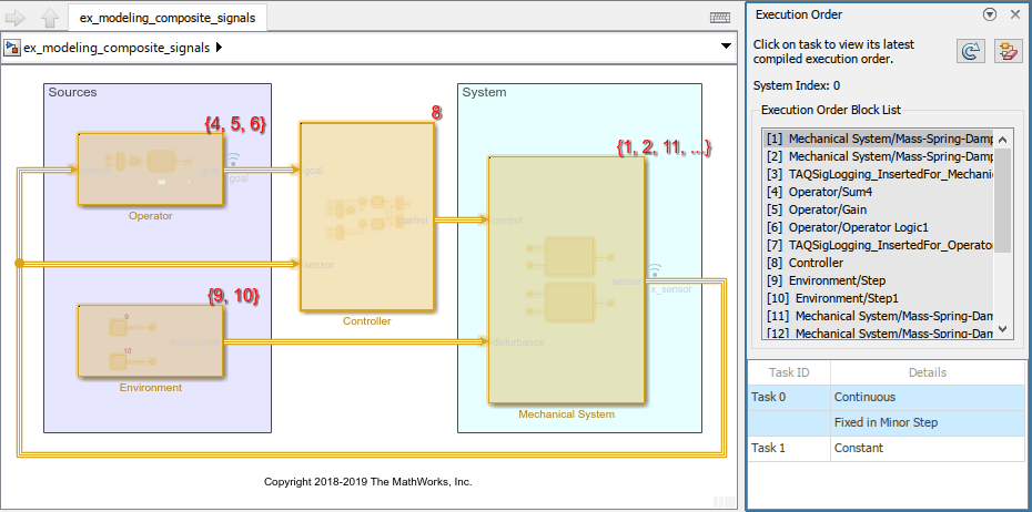
New Execution Order pane for ex_modeling_composite_signals.slx

Usability improvements in the Simulation Data Inspector

The Simulation Data Inspector has several improvements to help you control the visualization of signals for better data analysis.

  • When you add new signals to a plot, you can now choose to preserve axes scaling or automatically scale axes limits to view the newly added data. Previously, axes limits were always automatically scaled when you added new signals to a subplot.

  • Access subplot-specific operations, such as performing a fit-to-view in y for an individual subplot, from the context and subplot menus.

  • Live streaming improvements allow you to change the time span and time axis limits in an intuitive way. Previously, changing the time axis limits during live streaming also changed the time span. Now, the time span remains fixed when you change the minimum or maximum time axis limit. When you change the time span during live streaming, the minimum time axis limit remains the same and the maximum time axis limit adjusts such that t-Axis max = t-Axis min + Time span.

  • The Import dialog box now has an option to select all or none of the check boxes when importing data from the workspace or a file.

Improved signal selection for XY plots

With the improved XY Data dialog box, you can easily add and manage signals in XY plots. Previously, you had to use the Shift or Ctrl key to select more than one signal from the signal table then drag the signals onto the XY plot.

Now you can select multiple check boxes in the signal table to add signals to the XY Data dialog box. Then, use the x-Axis and y-Axis drop-down menus to manage how signals are paired for easy plotting.

You can also now perform a fit-to-view in x or y when viewing data in an XY plot.

Log nonvirtual buses that contain variable-size signals

In normal and accelerator mode simulation, you can now log:

  • Nonvirtual buses that contain variable-size signals directly or in nested buses

  • Buses with nested nonvirtual buses that contain variable-size signals

In normal mode simulation only, you can now log:

  • Arrays of buses with nonvirtual buses that contain variable-size signals

Set signal comparison constraints programmatically

Use name-value arguments to set comparison constraints like the sensitivity to data type, time vector, or start and stop times when comparing two signals programmatically. For more information, see Simulink.sdi.compareSignals.

Load MLDATX files and export data using the Playback block

There are two enhancements to the Playback block in R2023a:

  • In R2022b, you could add data to the Playback block from the workspace, a file, and the Simulation Data Inspector, but you could not aggregate and export that data outside the Simulink environment. Now, you can take data that has been added to the Playback block from different sources (linked to from the source or saved in the model) and export that data to the workspace or a file.

  • The Playback block now supports loading data from a Simulation Data Inspector session file. Adding data from a native MLDATX file format speeds up loading time and allows you to selectively load individual signals from large data sets.

Access diary information for simulations running with parsim

Starting in R2023a, you can access diary information about simulations that run on parallel workers. When running simulations with parsim, you can access the information about warnings, status updates, or user-printed messages. To access this information, use the Diary field in the ExecutionInfo struct of the SimulationMetada property of each Simulink.SimulationOutput object.

Pause complex port domain type propagation for Simscape blocks

For Simscape blocks, port domain type propagation is the process that computes port domain types of all linked connection ports. In complex models where propagation can take longer to complete, the Simulink editor is locked for editing. Starting in R2023a, you can suspend propagation and resume editing the model by clicking the Pause button on the status bar.

For more information, see Port Domain Type Propagation: Speed up editing complex models (Simscape).

 Functionality being removed or changed

get function for Simulink.SimulationOutput object issues error if specified property does not exist on object

Behavior change

Prior to R2020a, the get function returned empty ([]) if the specified Simulink.SimulationOutput object did not have the specified property. Since R2020a, the get function has issued a warning while still returning empty in this situation. Starting in R2023a, the get function issues an error and does not return an output argument.

To query whether a Simulink.SimulationOutput object has a given property, use the find function. The find function returns empty ([]) and does not issue a diagnostic when the object does not have the specified property.

Component-Based Modeling

Use local solver for model reference at any location in model hierarchy

Starting in R2022a, you could configure a Model block in the top model of a model hierarchy to use a local solver to compute results for the model reference. In R2023a, you can configure a Model block anywhere in a model hierarchy to use a local solver, including Model blocks inside model references that use local solvers.

Expression mode support and dialog box updates in Variant Assembly Subsystem block

You can use Boolean conditional expressions to switch between variant choices of Variant Assembly Subsystem blocks. Using conditional expressions enable you to change the active choice during different stages of simulation and code generation without modifying the block. You can generate code that contains active and inactive choices with meaningful names.

In the Variant Assembly Subsystem block dialog box, you specify a variant control variable and an enumeration class with model or subsystem filenames as its members. On successfully validating these parameter values, the block adds the enumerated members as its variant choices and generates conditional expressions for each of its choices. To add more variant choices, add members to the enumerated class. To remove variant choices, delete corresponding members from the enumeration class. For more information, see Add or Remove Variant Choices of Variant Assembly Subsystem Blocks Using External Files.

Previously, you could use only labels to switch between variant choices.

To support the expression mode, the block dialog box has been reorganized:

  • The Main and Reference tabs are merged. All the parameters in these tabs are placed in the same space. The Variant choices table in the Reference tab is removed.

  • A Variant Assembly section is added for variant assembly related actions. The newly introduced parameters Variant control variable and Variant choices enumeration parameters are available in this section. These parameters support expression mode workflows.

  • The Validate button is no longer available to evaluate the variant choices specifier that you specify. Instead, click the Refresh button to evaluate the specifier. In expression mode, the values that you specify for Variant control variable and Variant choices enumeration are evaluated on clicking the Refresh button.

Identify potential inconsistencies in variant choices controlled from mask or model workspace

You can identify potential inconsistencies in the choices of variant blocks that are controlled from mask parameters or from mask or model workspace variables early in the development process during the update diagram. Early detection saves you valuable time and improves product quality. To enable early detection, set the Variant activation time parameter of the variant block to update diagram analyze all choices. For more information, see Approaches to Control Active Variant Choice of a Variant Block Using Mask or Model Workspace.

Previously, you could analyze such variant choices only in the later stages of the development process.

Conditionalize insertion options and create subsystem choices with adaptive interfaces inside Variant Subsystems

When you drag a selection box around an empty area inside a Variant Subsystem block, the action bar shows choice insertion options that are based on the type of subsystem choices in the block. From these options, select Variant Subsystem Choice to add a new subsystem choice. The subsystem choice that you create adapts its interface from the Variant Subsystem block. The choice has the same number and types of input and output ports as the Variant Subsystem block. For more information, see the "Include Subsystem Block as Variant Choice" section in Implement Variations in Separate Hierarchy Using Variant Subsystems.

Previously, the options in the action bar were not conditionalized. Also, the newly created subsystem choice had only one input and one output port.

Support for continuous states with startup variant blocks

You can now simulate and generate code for startup variant blocks that are connected to continuous state blocks. Previously, you could use startup variant blocks only with discrete blocks. For information on the capabilities of startup, see startup.

Group variant parameter values in a single structure array in generated code

Use variant parameter banks to group variant parameters that share the same variant conditions into a structure in the generated code. A simple pointer switching mechanism enables you to switch the set of active parameter values in the code based on variant conditions. You can set code generation properties for the variant parameter bank which allows you to customize code placement and specify the memory section to place the parameter values in the compiled code. Variant parameter banks are supported only for variant parameters with startup variant activation time.

The code that you generate using Embedded Coder contains all choice values grouped into a structure array based on the variant conditions. The code uses a pointer variable to access values from the structure array; this pointer is initialized based on variant conditions in the model_initialize function. Parameter bank switching using a pointer variable avoids copying the choice values into the main program memory and improves the efficiency and readability of the generated code.

Previously, for variant parameters with startup activation time, the values of the parameters were inlined in the model_initialize function in the generated code, which involved reading and copying all parameter values into the program memory. This behavior is still applicable when you generate code using Simulink Coder.

For more information, see Simulink.VariantBank and Simulink.VariantBankCoderInfo.

Enhancements to the Variant Manager for Simulink support package

  • Manage variant parameters from Variant Manager

    The model hierarchy table shows variant parameters available in the workspace used by the model in a new tab view named Variant Parameters. You can edit the Condition and Value properties from the model hierarchy table or use the context menu to open the Simulink.VariantVariable dialog box to edit the properties.

  • Improved user interactions in the Control Variables table

    • Autocomplete control variable names on typing in the Name column.

    • Filter table rows based on a search string.

    • Show or hide the VAT and Source columns in the table.

  • Improved name and tooltip for Stateflow variant transitions

    The Stateflow view indicates the source and destination states of a variant transition in the Name column and shows additional information in the tooltip.

  • Support for startup variant activation time in Variant Reducer

    When you reduce a model that contains a variant block with startup activation time, Variant Reducer retains the block and any blocks connected to it in the reduced model. Previously, reduction of such models resulted in an error.

Programmatically refresh variants, linked blocks, and Model blocks

Starting in R2023a, you can use the Simulink.BlockDiagram.refreshBlocks function to programmatically refresh all variants, linked blocks, and Model blocks in a loaded model.

This function provides a programmatic alternative to the Refresh Blocks button in the Simulink Toolstrip. This button is on the Modeling tab under the Update Model button arrow.

The Model blocks update only when the Model block version mismatch and Port and parameter mismatch configuration parameters are set to none or warning. The Model blocks do not update when either configuration parameter is set to error.

To refresh blocks in referenced models, call this function for each referenced model.

Integrate Python functions with Simulink using Python Importer

Starting in R2023a, you can integrate Python functions with Simulink using the Python Importer within Blockset Designer. Use this feature to import python functions and packages to Simulink and generate a custom block for each function.

Specify Python files containing one or more function definitions in Files to import or Python packages containing one or more Python files in Packages to import. You can also specify a directory containing files to include in the package published by Blockset Designer in Python Folder.
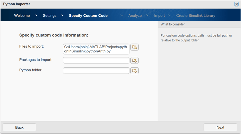
Python Importer with path specifying the location of python file to import to simulink

The Python Importer identifies all the functions specified in the Python files. You can select the functions for which the importer creates a custom block inside a Simulink library.

You can use the blocks from the library in your model or publish the blocks as a blockset using the Blockset Designer.
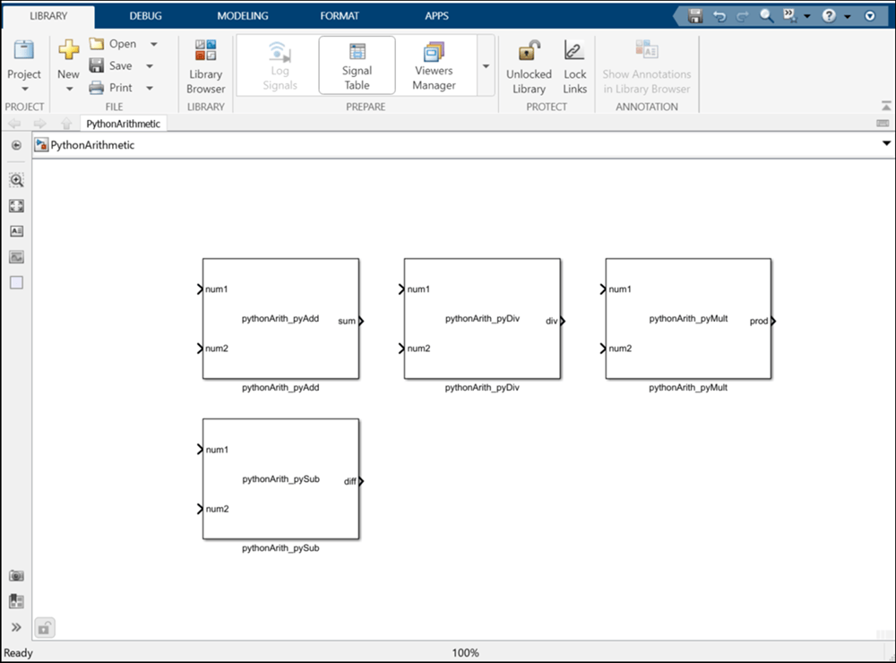
Simulink library created by the python importer with four system blocks for each of the identified python function

Discard changes in individual subsystem files without reversing all modifications in a model

The changes that you make to a particular subsystem file from its instance can be locally discarded. Previously, you could reverse your actions to get back to a desired state, but this process discarded all changes made in any of the subsystem files within the model hierarchy.

For example, to discard the changes in subsystem file SubRef1 made while editing its instance Topmodel/Subsystem Reference Block-1, close SubRef1. You will get a dialog box asking whether to save the subsystem file before closing. Click No. This action reverts changes in all the instances of the subsystem file.
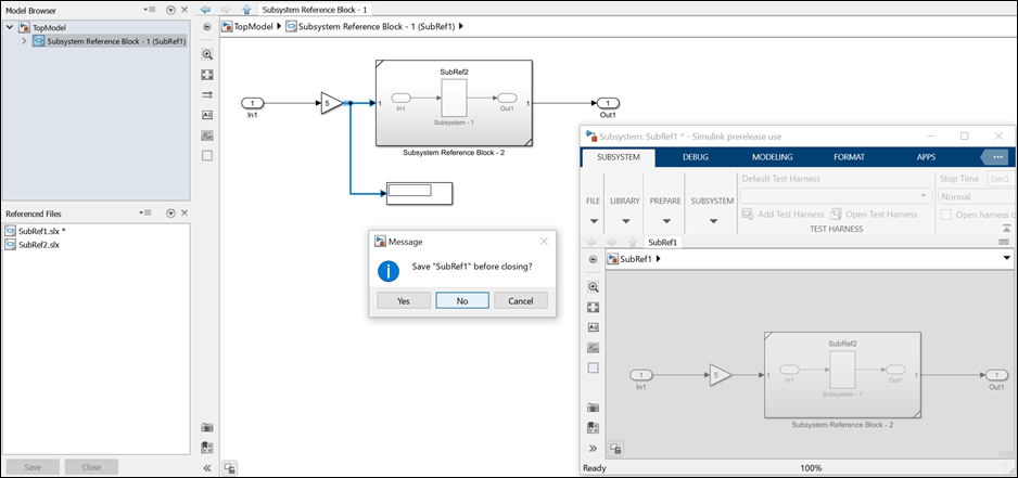
View of subsystem file SubRef1 and its instance Topmodel/Subsystem Reference Block-1. In the center, the message window displays whether to save the SubRef1 before closing.

Initial state parameter ignored for referenced models in normal mode

Starting in R2023a, for referenced models that simulate in normal mode, simulation ignores the Initial state configuration parameter.

Support for web browser display widget in mask editor

Starting in R2023a, the mask editor supports the web browser display widget. Enter the address in the URL property. The website opens in a preview of the dialog box.
web browser display widget

For more information, see Controls

Create cross-port constraints to validate signals among ports of the same masked block

Starting in 2023a, you can create cross-port constraints among input and output ports of the same masked block. The predefined rules available are Same Data Type and Same Dimensions. For example, you can constrain the input and output port signals to be of same data type. You can also set parameter conditions with mask parameters while defining cross-port constraints. The cross-port constraints are validated when you compile the model.

To create cross-port constraints, specify the name of the constraint, then set the rules and parameter conditions appropriately.
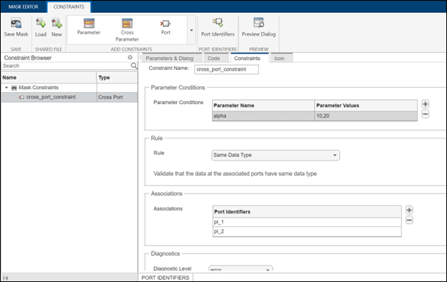
cross port constraint

Organize mask callbacks and initialization code in a MATLAB file

Starting in R2023a, you can write mask initialization, parameter, and dialog control callbacks in a separate MATLAB class file instead of storing it with the mask object. The advantages of using a MATLAB file are:

  • Organization of all mask callbacks in a single file.

  • Enhanced debugging experience. You can use all code debugging capabilities provided by the MATLAB editor, such as breakpoints, to debug your initialization and mask callback code.

  • Improvement of the memory footprint of the masks, as callbacks are no longer in memory but rather are in a MATLAB file on the disk.

  • Ability to edit the mask callback code using either the mask editor or the MATLAB editor.

  • Option to package the MATLAB class file along with the model.
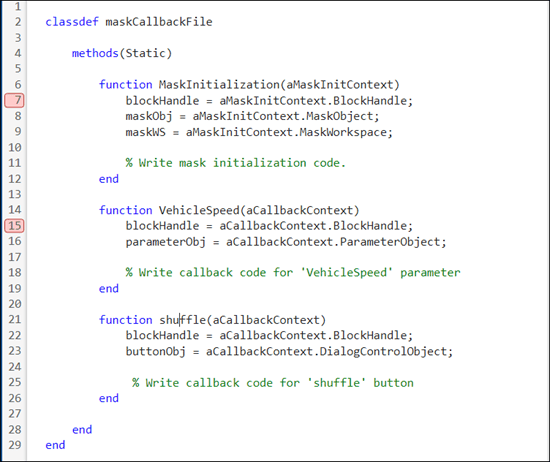
mask callback in m file

For more information, see Organize Mask Initialization and Callbacks in a MATLAB File

Authenticate usage and code reusability of your subsystem files in top model

Subsystem components are adaptable to environments. However, you can get undesired results if you use a component out of context. In R2023a, you can mark the test environments of a subsystem file that produce the intended results as unit tests.

Use the Unit Test features available in the Simulink toolstrip to:

  • Specify valid testing environments.

  • Capture signatures to diagnose and resolve invalid use of components.

  • Generate code for subsystem components to re-use in the top model.

Display of Simulink toolstrip with Unit Test features

For more information, see Validate Subsystem Reference Use and Build Model Using Component Codes.

Create self-modifiable referenced subsystems using mask initialization code

You can now make instance-specific changes in the contents of a masked subsystem file using the initialization callback of the system mask. To make changes, set the subsystem file as self-modifiable. In a self-modifiable subsystem file, you can:

  • Modify the blocks inside a masked subsystem reference instance.

  • Allow the masked subsystems inside a masked subsystem reference instance to self-modify.

For more information, see Create Self-Modifiable Subsystem Reference Using System Mask.

Simulink unit updates

Simulink units now support these prefixes as announced at the 27th meeting of the General Conference on Weights and Measures (CGPM).

PrefixFactorSymbol
quecto10-30q
ronto10-27r
quetta1030Q
ronna1027R

 Functionality being removed or changed

Variant blocks issue warning when blocks do not inherit variant activation times from their Simulink.VariantControl variables

Warns

Starting in R2023a, variant blocks issue a warning if the blocks do not inherit the activation times from their variant control variables of type Simulink.VariantControl, if any. All the Simulink.VariantControl variables of a variant block must have the same activation time. In previous releases, the blocks did not issue the warning.

If this change impacts your model, set the Variant activation time of the variant blocks to inherit from Simulink.VariantControl.

For more information, see inherit from Simulink.VariantControl.

Define shared constraints in XML file

Warns

Starting in R2023a, you can define the shared constraints in XML files. The advantages of defining in an XML file are that you can edit the data and compare the file with a previous version. If you have shared constraints authored in a MAT-file, you can convert it to an XML file using the method Simulink.Mask.Constraints.convertMatToXML(<matFilleName>, <xmlFileName>). matFileName is the name of the MAT file to be converted and xmlFileName is the name of the XML file to be created. Simulink no longer allows you to define the shared constraints in MAT files. However, the existing constraints continue to work until you open the mask editor.

For more information, see Share Parameter Constraints Across Multiple Block Masks

lcc-win64 compiler will be removed

Still runs

The lcc-win64 compiler will be removed in a future release. For information about supported compilers, see Supported and Compatible Compilers - Windows.

Project and File Management

Dependency Analyzer: Perform a block-level dependency analysis

You can now perform a block-level dependency analysis for your project or model hierarchies. For an example showing how to identify the impact of changing a single block on the other files in your design, see Perform Block-Level Impact Analysis Using Dependency Analyzer.

Dependency Analyzer: Analyze files and folders with or without a project

Starting in R2023a, you can access Dependency Analyzer from the MATLAB Apps gallery. You can now perform a dependency analysis on files and folders that do not belong to a project. For more information, see Dependency Analyzer.

Project Preferences: Recreate empty project folders in Git repositories

Git does not track empty folders and ignores them when you commit. MATLAB now enables you to recreate an empty folder structure in a project under Git source control. Doing so is useful for small projects intended for training or as procedure templates.

For large projects, to avoid performance issues on startup, clear Recreate empty project folders in a project under Git. For more information, see Set MATLAB Projects Preferences.

Project API: Determine if file is under project root folder

You can now programmatically determine whether a file or a folder is under a project root folder by using the matlab.project.isUnderProjectRoot function.

Project API: Export subset of project files to archive

You can now programmatically export a subset of project files to an archive by specifying a user-defined export profile in the export function.

Project Sharing: Include only specific files in project archive using export profile

You can now use an export profile to include only files with particular labels in a project archive. This option is useful if the files you need to share are only a small subset of a large project. For more information, see Archive Projects.

Model Comparison: Save printable reports without screenshots

You can now save comparison reports without screenshots. Before you save the comparison results as a printable report, in the Command Window, enter:

s = settings().comparisons.slx.DisplayReportScreenshots;
s.TemporaryValue = false;

For more information, see Save Printable Report.

Text Comparison: Automate comparison report generation for continuous integration (CI) workflows

Starting in R2023a, you can programmatically publish comparison reports for plain text files, MATLAB scripts, and text-based source code files. Automate report generation for continuous integration (CI) workflows using the visdiff function:

comparison = visdiff(textfile1,textfile2);
file = publish(comparison);
web(file)

Text Comparison: Save comparison results as PDF or DOCX reports

You can now use the Comparison Tool to publish text comparison results as PDF or DOCX reports. For more information, see Compare Text Files.

Source Control in MATLAB Online: Detect and extract conflict markers from text and binary files

In MATLAB Online, you can now detect conflict markers added by Git in text and binary files. Extract conflict markers to repair corrupted files.

Source Control in MATLAB Online: Save uncommitted changes by creating a Git stash

In MATLAB Online, you can now save uncommitted changes by creating a Git stash.

Source Control in MATLAB Online: Manage Git remote repositories locally using Branch Manager

In MATLAB Online, you can now manage multiple remote repositories from a local Git repository. Use Branch Manager to perform these tasks:

  • Add, edit, and delete remote repositories.

  • Fetch from all remotes or individual remotes.

  • Prune remote branches from all or individual remotes.

  • Open selected remotes in a web browser.

  • Create new local branches that track remote branches.

  • Delete remote branches.

Project Comparison in MATLAB Online: Compare project definition files

Starting in R2023a, when you compare folders in MATLAB Online, MATLAB detects whether they are project root folders. MATLAB looks for and compares the project definition files stored in the resources or .SimulinkProject folder. Project definition files contain information about the project path, project settings, shortcuts, labels, and referenced projects. For more information, see Compare MATLAB Projects in MATLAB Online.

Dependency Analyzer in MATLAB Online: Investigate circular dependencies using the Project Hierarchy view

You can now investigate how projects in your hierarchy relate to each other and identify projects that introduce circular dependencies using the Project Hierarchy view in MATLAB Online. For more information, see Explore the Dependency Graph, Views, and Filters.
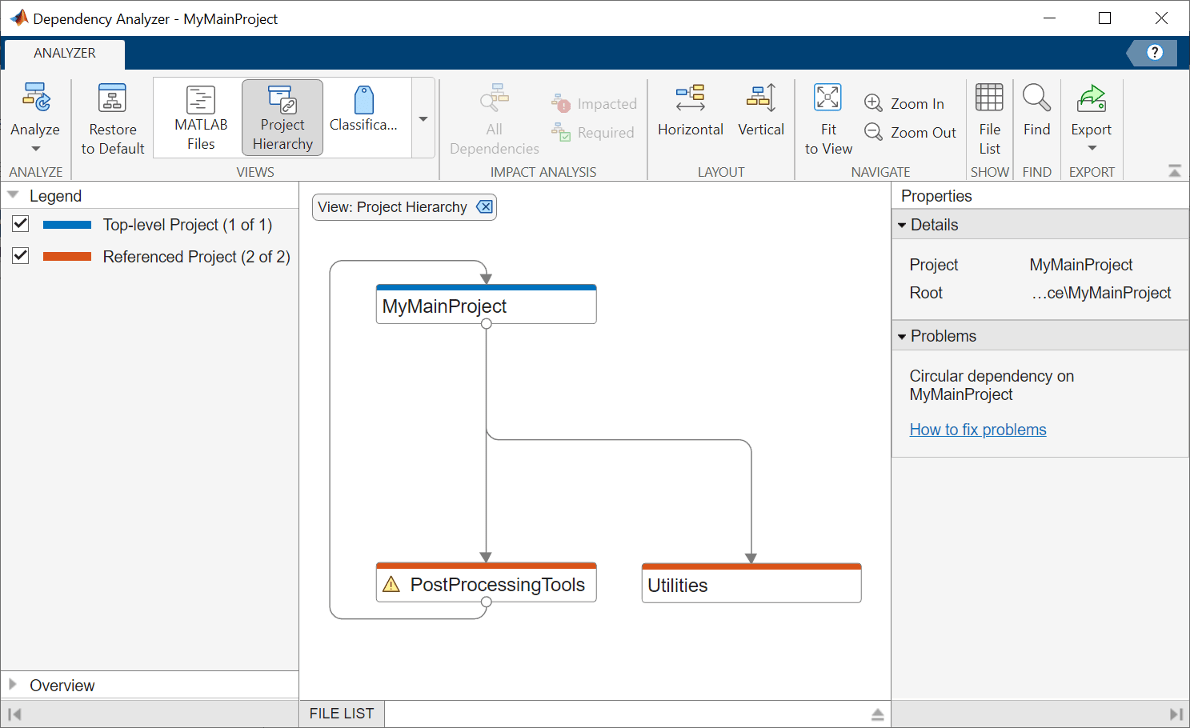
Project Hierarchy view shows the relations between the different projects in the hierarchy. Warning about the circular dependency in the Properties panel on the right.

 Functionality being removed or changed

XML comparison type will be removed in a future release

Still runs

XML comparison type will be removed in a future release. Overriding the default comparison type by specifying "xml" will not be possible in a future release. In R2023a, scripts that use visdiff(filename1,filename2,"xml") continue to work. See visdiff.

Data Management

Signal Editor tool updates

The Signal Editor tool has these updates:

  • Import and Export commands now appear directly on the toolstrip in the File section. In previous releases, these commands were contained in the Save and Open menus, respectively.

  • Snap to incremental values in the X and Y grids.

Root Inport Mapper updates

The look and feel of Root Inport Mapper has changed. Continue to use it as in previous releases. Changes include:

  • The link from MAT-file shortcut Ctrl+Shift+M has changed to Ctrl+Shift+L.

  • Root Inport Mapper icons have changed slightly.

    ActionOld IconNew Icon

    Open

    Save

    Save As

    From Spreadsheet

    From MAT-file/Edit MAT-file

    From Workspace

    Signals

    New MAT-file

    Options/defaults

    Map All

    Map Selected

    Map Unconnected

    Map Failed

    Map Warned

    Apply to Model

    Generate Script

Simulink.ValueType object enhancements

Starting in R2023a, Simulink.ValueType objects:

  • Support Simulink.Bus objects as data types. When the value type specifies a bus object data type and a nonscalar dimension, the value type specifies an array of buses.

  • Are supported as data types of Simulink.Signal and Simulink.Parameter objects.

Package Simulink data dictionary with referenced subsystems for better reusability and scoping

You can attach a data dictionary to a subsystem file to store data objects and reuse them in the child blocks and instances of the subsystem file. When you attach a data dictionary with a subsystem file, you can:

  • Define all types of data objects, such as variables, bus objects, and enumeration types.

  • Achieve data encapsulation, as the data dictionary is accessible only to the child blocks and instances of the subsystem file.

  • Scope the symbol resolution path for any child block within the subsystem reference boundary.

For more information, see What Is a Data Dictionary? and Attach Data Dictionary to Subsystem Reference.

Get data type of block parameters

To get the data type of a block parameter when its value is set to Inherit: Inherit via internal rule, use the Simulink.Block.getInternalDataType function.

Multiple consistent definitions of symbol allowed in model hierarchy

Previously, multiple definitions of a symbol could exist across the data dictionaries in a model hierarchy only under these conditions:

  • Each model in the hierarchy could see only one definition.

  • Definitions were consistent across models in the hierarchy (unless consistency checking was disabled by setting the model parameter EnforceDataConsistency to off).

Symbol definitions are consistent when their symbol name, class type, and all property values are the same.

In R2023a, data dictionaries in a model hierarchy can contain multiple consistent definitions of a symbol, even if one model can see multiple definitions for that symbol. These definitions can come from the base workspace, connected Simulink data dictionaries, or visible library dictionaries.

If definitions for the same symbol are consistent, you can simulate the model in normal, accelerator, and rapid accelerator modes, and generate code for the model.

For more information, see Considerations Before Migrating to Data Dictionary.

Support for uint32 data type for enumerations

In R2023a, Simulink supports simulation and code generation for models that use enumerations with a uint32 data type.

  • Create Simulink enumerations with a uint32 data type by calling Simulink.defineIntEnumType with the 'StorageType' argument set to uint32.

  • Create Simulink enumerations in a data dictionary with Storage Type set to uint32.

  • Simulate models that use class-based enumerations with a uint32 base type.

  • Generate C and C++ code for ERT, GRT, and AUTOSAR-based targets when the model uses enumerations with a uint32 base type.

  • Import AUTOSAR XML descriptions of enumerations with a uint32 data type.

Enumeration values must be less than or equal to intmax('int32').

For more information, see Define Simulink Enumerations.

Improve code generated for functions that include blocks that request time values by specifying target platform clock resolution

Starting in R2023a, for model functions that include blocks that request absolute or elapsed time values, you can improve the entry-point code generated for those functions by configuring the model to use a specific clock resolution. Clock resolution is the smallest increment of a clock value. For example, if a clock increments its value once per second, the clock resolution is one second.

Benefits of specifying a clock resolution include:

  • Clock resolution specification that aligns with target environment clock requirements. For models configured to use a service code interface, a specified clock resolution results in code that reads time values that are more accurate.

  • Decoupling of the clock resolution and the solver properties that Simulink uses during simulation, such as the fixed-step size and sample times.

  • Influencing the data type that Simulink and the code generator use to represent time values. For example, in normal, accelerator, and rapid accelerator modes, Simulink uses the specified value to deduce fixed-point data types, which produces fixed-point simulation and generated code results that match.

  • Potability of models between code interface configurations. You can attach a model that has a specified clock resolution to a shared Embedded Coder Dictionary that defines a data or service code interface configuration.

  • Relevant generated code that is easier to read.

To specify a clock resolution for the code generator to apply for a model, configure the model with these model configuration parameter settings:

  • Set System target file (SystemTargetFile) to ert.tlc.

  • Set solver parameter Type (SolverType) to Fixed-step.

  • Set Clock resolution (ClockResolution) to a scalar value of type double, which represents the resolution in seconds.

For more information, see Clock resolution and Specify Clock Resolution Used by Target Environment Clock (Embedded Coder).

Block Enhancements

New Float Extract Bits block

The Float Extract Bits block accepts a signal containing floating point data and outputs a signal containing the binary representation of the data.

Math Function block supports 2^u

The Math Function block now supports the 2^u function. The MATLAB equivalent is 2.^u (see power).

Signal Editor block updates

The Signal Editor block dialog has these updates:

  • The Launch Signal Editor button has moved to the top of the block parameters dialog box.

  • The Signal properties section is reorganized.

  • In the Signal properties section, the new Apply properties to active signal in all scenarios check box lets you apply the specified signal properties to the active signal with the same name in all scenarios.

 New Neighborhood block parameters: Stride, Processing offset, and Processing width

In R2023a, the Neighborhood block has new parameters. Use these parameters to configure the behavior of a Neighborhood Processing Subsystem block:

  • Use the Stride parameter to configure the Neighborhood Processing Subsystem block to skip a number of elements in the input matrix between each iteration.

  • Use the Processing offset and Processing width parameters to configure a region of interest within the input image. The Neighborhood Processing Subsystem iterates over only this region.

For an example of how to configure a region of interest, see Specify Region of Interest for Neighborhood Processing.

 Compatibility Considerations

The number of elements of the new Stride and Processing offset parameters must match the number of dimensions of the input matrix. The default Stride and Processing offset parameter values are [1 1] and [0 0] respectively, which are valid for only 2-dimensional input data. For models that use Neighborhood Processing Subsystem blocks to process n-dimensional data, you must change the Stride and Processing offset parameter values to each contain n elements.

To preserve the behavior of models from before R2023a, use the value 1 for each element of the Stride parameter value and 0 for each element of the Processing offset parameter value. For example, for a Neighborhood Processing Subsystem block that processes multichannel image data as a 3-dimensional matrix, set the Stride parameter to [1 1 1] and the Processing offset parameter to [0 0 0].

Hit Scheduler block supports vector signals

The Hit Scheduler block supports vector inputs and produces a vector output when you configure the block to produce a signal output. Vector inputs are not supported for blocks that produce a function-call output. By using vector signals, you can use one Hit Scheduler block to schedule major time steps for a variable-step solver based on multiple signals in your model.

Persistent Panels tab in Simulink Toolstrip

When you add a dashboard panel to a model, the Panels tab appears in the Simulink Toolstrip and shows options for managing and editing panels.

Previously, the Panels tab was only visible when a panel was selected. Starting in R2023a, the Panels tab stays visible when no panel is selected.

If you delete all panels, the Panels tab stays visible while the Simulink model that you are working in is open. If you then close and reopen the model, the Panels tab is no longer visible.

The Panels tab also contains these new options:

  • To add an empty panel, on the Panels tab, click Add Empty Panel.

  • To rename a panel, on the Panels tab, click Rename Panel. The Parameters tab of the Property Inspector opens. In the Name text box, enter the new panel name.

  • To hide a panel, select the panel. Then, on the Panels tab, click Manage Panels and select Hide Panel.

    Note

    To unhide the panel, click the Manage Panels button. In the Manage Panels menu that appears in the lower right corner of the canvas, click the image of the panel.
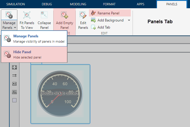
The image shows a Simulink model window. In the canvas, there is a panel that contains a Circular Gauge block. The panel is selected. In the Simulink Toolstrip, the Panels tab is open, and the Manage Panels split button is expanded to show the Manage Panels and Hide Panel buttons. The Hide Panel, Add Empty Panel, and Rename Panel buttons are highlighted in red.

Callback Button blocks in Dashboard Library and Customizable Blocks Library have same customization options

Starting in R2023a, the Callback Button block from the Dashboard library has the same customization options as the Callback Button block from the Customizable Blocks library. You can change the appearance of the block to look like a real button.

To customize the Callback Button block from the Dashboard library, enter design mode and open the Design tab of the Property Inspector:

  1. Select the block.

  2. In the Simulink Toolstrip, on the Button tab, click Edit.

  3. On the toolbar that appears above the block, click Open Design Tab.
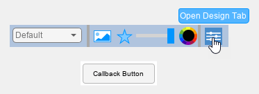
Callback Button block from the Dashboard Library in design mode with a toolbar above it, and the pointer over the Open Design Tab button in the toolbar

In design mode, you can:

  • Upload an image and an icon for each button state.

  • Specify the position of the icon relative to the state label.

  • Specify the text, color, and position of the label for each button state.

  • Upload a foreground or a background image, or set a solid background color.

    The state images are not visible when you set a solid background color. To make the state images visible, in the Property Inspector, on the Design tab, in the Background Image component, turn off Use Background Color.

To configure the state image, icon, label color, and label opacity, use the toolbar above the block.

Use the Design tab in the Property Inspector to:

  • Specify the text and position of the label for each button state.

  • Specify the icon position.

  • Upload a foreground image.

  • Upload a background image.

  • Set a solid background color.

When you finish editing the design, click the X in the upper-right of the canvas to exit design mode.

Fcn block restored to User-Defined library

The Fcn block has been restored to the Simulink > User-Defined library.

Selector and Assignment blocks support custom integer for index signal

Starting in R2023a, you can specify integer values of custom width (for example,15-bit integer or 23-bit integer) as index signals to the Selector and Assignment blocks. This enhancement allows you to customize your selection of index signal data. When you use Selector and Assignment blocks, you must specify Fixed-point datatype with Word length less than or equal to 128, Slope equal to 1 and Bias equal to 0.

In this example, a 15-bit unsigned integer is used as index signal to the Selector block.
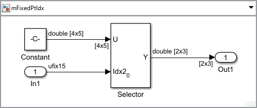
15-bit unsigned integer used as index signal for the Selector block.

The index signal is configured using the Inport block parameters.
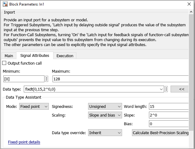
Use Data Type Assistant to configure the 15-bit unsigned integer used as index signal.

Enhancements to C Caller and C Function blocks and custom code integration

In R2023a, C Caller and C Function blocks and custom code integration have these enhancements.

  • C Caller and C Function blocks support using namespaces for types, variables, functions, and classes in your C++ code.

  • C Caller and C Function blocks support parameter value implicit casting to specified data type.

  • C Function block supports fixed-point data type. You can use the C Function block to:

    • Input signals or parameter values of fixed-point data type, pass them to external C functions, or output them as signals.

    • Process fixed-point data inside the block.

  • C Caller block supports global variables in matrix form and structures with a matrix field as input and output.

  • When you integrate custom code, you can now use dependent dynamic libraries (DLLs) located in any drive in Windows, including a network drive. With this enhancement, your dependent dynamic library does not have to be in the same drive as your working folder.

Selector block supports variable-size input signal for Index vector(dialog) and Starting index(dialog) index options

Starting in R2023a, when you configure the Selector block for a 1-D variable-size input signal, you can specify the Index Option as Index vector(dialog) or Starting index(dialog). For more information, see Variable-Size Signal Basics.

Bus Creator block supports variable-size input signal with upper bound smaller than upper bound of block input port

Starting in R2023a, the Bus Creator block supports variable-size input signals with upper bounds smaller than the upper bound of the corresponding Bus Creator input port. You can configure the upper bound of a Bus Creator input port by specifying the corresponding Simulink.BusElement Dimensions. For more information, see Simulink.BusElement.

In this example, variable-size input signals with upper bounds of 2 and 10 are connected to their corresponding Bus Creator input ports with upper bounds of 3 and 12, respectively.
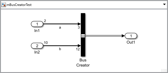
Bus Creator block accepts variable-size input signals with upper bounds 2 and 10 which are smaller than the corresponding Bus Creator block input port dimensions 3 and 12, respectively.

Parameter Writer block option to skip parameter validation

Starting in R2023a, you can disable parameter validation that occurs during normal mode simulation for Parameter Writer blocks. When parameter validation is disabled for a Parameter Writer block, normal mode simulation of the block is faster.

To locally disable parameter validation for a Parameter Writer block, select the block. Then, in the Property Inspector, clear Validate parameter.

To globally enable or disable parameter validation for Parameter Writer blocks, use the Parameter Writer block validation configuration parameter.

In Bus Element and Out Bus Element block enhancements

Starting in R2023a:

  • An Out Bus Element block at the top level of a model lets you specify the name of the top-level bus, signal, or message that appears in a parent subsystem or model.

  • The Property Inspector supports In Bus Element and Out Bus Element blocks.

  • Warning and error messages for In Bus Element and Out Bus Element blocks now link to the corresponding block in the block diagram, helping you quickly find the source of the warning or error. In previous releases, warning and error messages refer to a hidden block and do not provide a link.

Improved edit shape tool in Graphical Icon Editor

Use the edit tool to edit all supported shapes, for example, rectangles, ellipses, lines, and paths. To edit a shape, select the edit tool and then hover over the shape to view all the edit points forming it. Click an edit point to edit the shape.
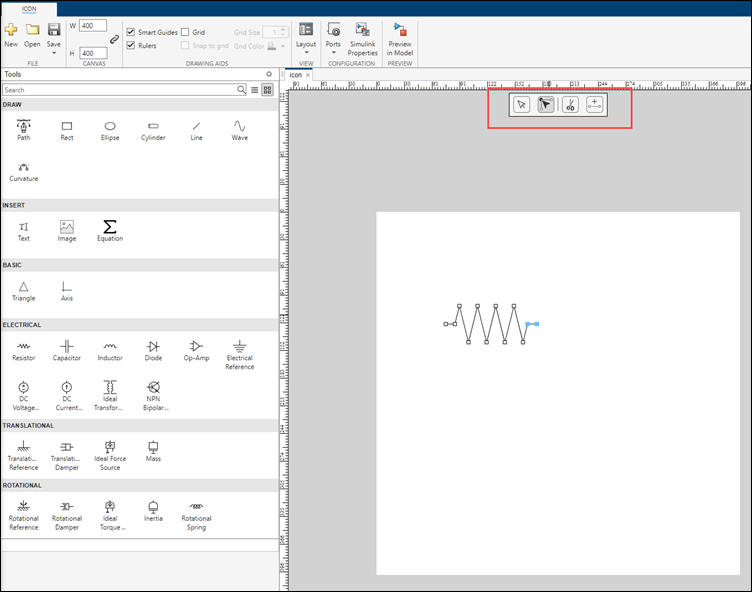
path editor

For more information, see Edit the Properties of Block Mask Icon and Its Elements

Plot n-dimensional data in mask look up table control

The mask lookup table control can now plot n-dimensional data. When plotting n-dimensional data, you can:

  • Visualize the data in contour, mesh, line, and surface plots.

  • Visualize a plot for selected dimensions or slices.

  • Select data in the table to highlight corresponding points in the plot.
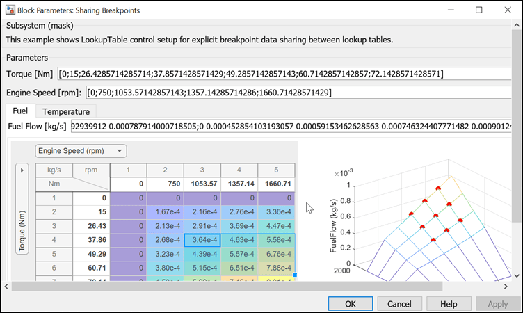
plot lookup table

For more information, see Visualize and Plot N-Dimensional Data Using Mask Lookup Table Control

Lookup Table Editor spreadsheet context menu update

The Lookup Table Editor spreadsheet context menu now has a Paste option.

 Functionality being removed or changed

Signal Builder block is not recommended

The Signal Builder block is not recommended. The Signal Builder block has been removed from the Simulink/Sources library. Use the Signal Editor block or other Simulink source blocks instead. Existing models continue to work.

For more information, see Migrate from Signal Builder Block to Signal Editor Block.

Connection to Hardware

Send and Receive data through Nanomsg-Next-Gen (NNG) using NNG Send and NNG Receive blocks

The Raspberry Pi Blockset now supports sending and receiving data through NNG on your Raspberry Pi board.

The NNG Send block sends data through NNG using publish and subscribe protocols. The NNG Receive block receives data through NNG using publish and subscribe protocols

Support added for 64-bit Raspberry Pi OS

You can now use the Raspberry Pi Blockset to generate code for the 64-bit Raspberry Pi OS.

To generate code, in the Configuration Parameters dialog box select Hardware Implementation and under Hardware board select Raspberry Pi (64-bit).

Support added for Raspberry Pi Bullseye OS

You can now use the Raspberry Pi Blockset to generate code for the Raspberry Pi Bullseye OS.

BMI160 IMU Sensor block updated to support application interrupts

The BMI160 IMU Sensor in the Raspberry Pi Blockset is updated to support advanced application interrupts. Use the block to generate Single tap, Double tap, High g detection, Any motion, Slow motion, Flat detection, and Data ready interrupts.

MATLAB Function Blocks

Set output variables of any dimension as variable size

You can now set output variables of any dimension to be variable size by clearing the Treat dimensions of length 1 as fixed size property. Prior to R2023a, the MATLAB Function block treated variables with at least one dimension of length 1 as fixed size. This property is enabled by default.

Name-Value Argument Validation: Use arguments blocks inside MATLAB Function blocks

In R2023a, you can use arguments blocks that validate name-value arguments in the MATLAB functions inside MATLAB Function blocks. You declare name-value arguments in an arguments block using dot notation to define the fields of a structure. See Validate Name-Value Arguments.

In this example code snippet, the structure named NameValueArgs defines two name-value arguments, Name1 and Name2. You can use any valid MATLAB identifier for the structure name and the field names.

function result = myFunction(NameValueArgs)
    arguments
        NameValueArgs.Name1
        NameValueArgs.Name2
    end
    ...
end

MATLAB Function blocks support most features of arguments blocks for name-value arguments, including size and class validation, validation functions, and default values. MATLAB Function blocks also support the namedargs2cell function.

MATLAB Function blocks do not support these features of name-value argument validation:

  • Name-value input arguments at entry-point functions

  • Name-value arguments from class properties using the structName.?ClassName syntax

See Generate Code for arguments Block That Validates Input and Output Arguments.

Output Argument Validation: Use arguments(Output) blocks inside MATLAB Function blocks

In R2023a, you can use arguments blocks that perform output argument validation in the MATLAB functions inside MATLAB Function blocks. Output argument validation declares specific restrictions on function output arguments. Using argument validation, you can constrain the class, size, and other aspects of function output values without writing code in the body of the function to perform these tests.

MATLAB Function blocks support most features of arguments blocks for output variables, including size and class validation, and validation functions. For repeating output arguments, MATLAB Function blocks do not support size validation, class validation, and validation functions.

See Generate Code for arguments Block That Validates Input and Output Arguments.

Input Argument Validation: Use any name for repeating input arguments inside MATLAB Function blocks

In R2023a, in MATLAB Function blocks, you can use any valid MATLAB identifier for the name of a repeating input argument inside an arguments block. MATLAB Function blocks only support a single repeating argument for a function.

In previous releases, MATLAB Function blocks supported only varargin as a repeating input argument.

Grow arrays with end+1 indexing inside MATLAB Function blocks

In R2023a, in MATLAB Function blocks, you can use the end+1 indexing syntax to grow the size of arrays. MATLAB Function blocks support growing arrays in this way either in linear code or in a loop. For example, you can use this code snippet inside MATLAB Function blocks:

...
a = [1 2 3 4 5 6];
a(end+1) = 7;

b = [1 2];
for i = 3:10
    b(end+1) = i;
end
...

To use this functionality, make sure that in the Property Inspector, in Properties > Advanced, the Support variable-size arrays check box is selected.

See Generate Code for Growing Arrays and Cell Arrays with end + 1 Indexing.

Use uint32 enumerations inside MATLAB Function blocks

In R2023a, you can use enumerations that derive from the base type uint32 inside MATLAB Function blocks. For members of uint32 enumerations, MATLAB Function blocks support values that are less than or equal to intmax("int32").

coder.read and coder.write: Read data from .coderdata file into your deployed application

In R2023a, you can use the coder.read function to read data from .coderdata files. In contrast with MAT-files that can be read only inside the MATLAB environment, you can read .coderdata files on any deployment platform that supports a file system. In addition, the .coderdata format supports most primitive and aggregate MATLAB data types, including arrays, structures, and cell arrays. So, the C/C++ code generated for coder.read can be used to read complex aggregate data from .coderdata files into your deployed application.

To export MATLAB data to .coderdata files, use the coder.write function. This function is not supported for code generation.

The code generated for coder.read has two distinct advantages over the code generated for the coder.load function:

  • You can update the data stored in .coderdata files without having to regenerate code, as long as the type and size of the new data matches those of the old data.

  • The data is not hard-coded in the generated code, thereby improving the readability of the generated code.

This is an example workflow that uses the coder.read and coder.write functions:

  1. Use the coder.write (MATLAB Coder) function at the MATLAB command line to store the data in .coderdata files. For example, create a file named myfile.coderdata by using these commands:

    c = rand(100);
    coder.write('myfile.coderdata',c);
    Wrote file 'myfile.coderdata'. You can read this file with 'coder.read'.
  2. In your MATLAB Function block, use the coder.read (MATLAB Coder) function to read data from the .coderdata files. For example:

    function y = fcn(x) %#codegen
    dataOut = coder.read('myfile.coderdata');
    y = x + mean(dataOut,"all");
    end
    
  3. Add input and display blocks. Pass input 1 to the MATLAB Function block and run the simulation.
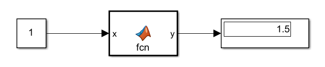
    Model reading data from .coderdata file.

  4. You can now update the data stored in myfile.coderdata to a different 100-by-100 array of double type. If you run simulation again, the model now reads and uses the new data.

    d = rand(100) - 1;
    coder.write('myfile.coderdata',d);

    

    Model reading data from modified .coderdata file.

For more information and examples, see coder.read, coder.write, and Data Read and Write Considerations (MATLAB Coder).

Code generation for more toolbox functions

In R2023a, you can generate code for many additional toolbox functions and objects. For a list of all functions and objects that are supported for code generation, see:

These are links to the release notes of some toolboxes that added code generation support in R2023a:

Computer Vision Toolbox

See Generate C and C++ Code Using MATLAB Coder: Support for functions (Computer Vision Toolbox).

Image Processing Toolbox

See C Code Generation: Generate code from additional functions using MATLAB Coder (Image Processing Toolbox).

Signal Processing Toolbox

See C/C++ Code Generation Support: Code generation for digital filter design, multirate signal processing, and waveform generation (Signal Processing Toolbox).

Statistics and Machine Learning Toolbox

See Generate C/C++ code for prediction using Gaussian kernel classification and regression models (requires MATLAB Coder) (Statistics and Machine Learning Toolbox).

Wavelet Toolbox

See C/C++ Code Generation: Automatically generate code for wavelet functions (Wavelet Toolbox).

Modeling Guidelines

Updates to modeling guidelines for code generation

Guideline for timer service interface in component deployment modeling

You can use guideline cgsl_0410: Timer service for component deployment to model export-function and single-rate, rate-based models that generate entry-point functions. You can configure and generate timer service interface code for:

  • Aperiodic exported functions generated from models that rely on elapsed time values (by using Discrete Time Integrator and Weighted Sample Time blocks).

  • Periodic entry-point functions generated from models that use blocks that rely on absolute time values (such as Sine Wave and Pulse Generator blocks).

  • Periodic entry-point functions generated from models that use blocks that rely on the elapsed time value in an aperiodic context.

Within a model, you represent requests for a clock tick implicitly when you use blocks that rely on a time value. For these blocks, depending on the context, the code generator assumes that the clock resolution is the sample period of the function or fixed-step size (fundamental sample time) of the model.

For more information about the timer service interface, see Generate C Timer Service Interface Code for Component Deployment (Embedded Coder).

Removal of code generation modeling guidelines

Starting in R2023a, these code generation modeling guidelines are removed.

Modeling GuidelineRationale
cgsl_0104: Modeling global shared memory using data stores Inconsistent with modeling by using a service interface. Conflicts with modeling guideline hisl_0013: Usage of data store memory
cgsl_0105: Modeling local shared memory using data storesInconsistent with modeling by using a service interface. Conflicts with modeling guideline hisl_0013: Usage of data store memory
cgsl_0205: Signal handling for multirate models Redundant. Use hisl_0042: Configuration Parameters > Solver > Tasking and sample time options
cgsl_0206: Data integrity and determinism in multitasking modelsRedundant. Use hisl_0042: Configuration Parameters > Solver > Tasking and sample time options
cgsl_0302: Diagnostic settings for multirate and multitasking models

Redundant. To verify the configuration parameters, use:

Guideline for check safety-related diagnostic settings for Stateflow

Starting in R2023a, the guideline "hisl_0311: Configuration Parameters > Diagnostics > Stateflow" no longer recommends that the configuration parameter Use of machine-parented data instead of Data Store Memory is set to none or warning because the configuration parameter has been removed. For information on the guideline, see hisl_0311: Configuration Parameters > Diagnostics > Stateflow.

Note that the configuration parameter was removed because Stateflow charts no longer support machine-parented data. You can check for machine-parented data and use the Upgrade Advisor to convert machine-parented data to chart-parented data store memory. For more information, see Consult the Upgrade Advisor and Check for machine-parented data.

R2022b

New Features, Bug Fixes, Compatibility Considerations

Docked Simulink Library Browser

The Library Browser button in the Simulink Toolstrip now opens a Library Browser that is docked as a panel in the Simulink window.

The Library Browser is in docked mode so that the Library Browser window stays to one side of the model and does not cover areas in the model canvas where you want to add items.

When you have multiple Simulink windows open, you can open a docked Library Browser in each one by clicking the Library Browser button of the respective window.

In docked mode, the Library Browser can be positioned at the left, right, or bottom of the Simulink window. To change the position of the Library Browser, click and drag the top of the Library Browser window to the new position, and release it in the blue area that appears.

To browse the Simulink libraries in your system and the blocks that they contain in docked mode, expand the tree on the Library tab. Use the layout button to switch between viewing the blocks in a single column One column layout button or in a responsive layout that adapts the number of columns to the browser width Responsive layout button.

The Library Browser is shown twice, in both instances displaying the commonly used blocks in the Simulink Library. In the image on the left, the blocks are arranged in one column, with the icon and name of each block on the same line. In the image on the right, the blocks are arranged in the responsive layout. The blocks are in two columns, with the name of each block underneath its icon.

You can also search for blocks and annotations by entering search terms in the search box or by selecting from the drop-down list of recent search terms. To view the results of the search, click the Search Results tab.

To add blocks to your model, you can drag block icons from the browser into the canvas.

A Library Browser that is not docked is in standalone mode. To open a Library Browser in standalone mode, on the Library Browser in docked mode, click the Launch standalone library browser button Launch standalone library browser button.

Use standalone mode to:

  • Add the same items to many Simulink windows.

  • View the Library Browser in full-screen mode.

  • Open, close, hide, or position the Library Browser programmatically.

  • Browse the libraries without opening a Simulink model.

For more information on the Library Browser in docked mode, see Library Browser. For more information on the Library Browser in standalone mode, see Library Browser in Standalone Mode.
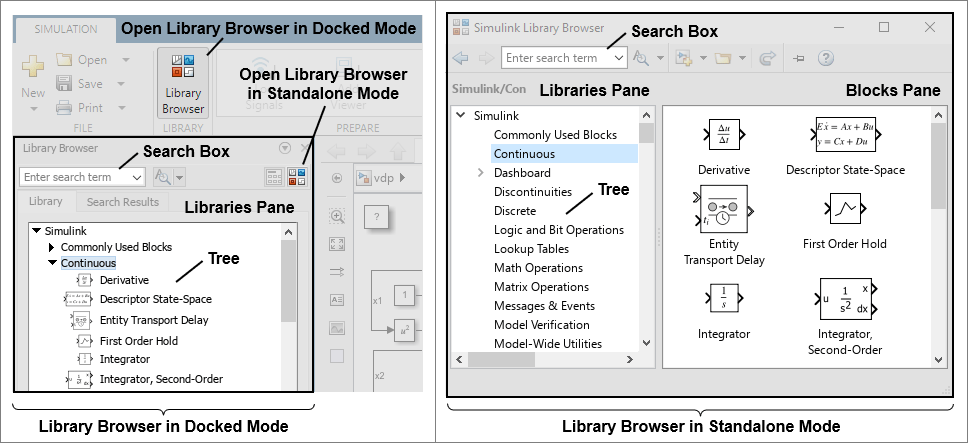
The left image shows the Library Browser in docked mode. In docked mode, the Library Browser has a single pane called the libraries pane. Labels are on the libraries pane, the tree that it contains, the search box, and the Library Browser button. The right image shows the Library Browser in standalone mode. In standalone mode, the Library Browser has two panes. The pane on the left is called the libraries pane. The pane on the right is called the blocks pane. Labels are on the libraries pane, the tree that it contains, the blocks pane, and the search box.

Simulink Block Parameters dialog box and Property Inspector display values of variables

When you specify the value of a Simulink parameter as a variable or as an expression that contains variables, the Block Parameters dialog box and the Property Inspector now display the value of the variable or the expression.

The text box where you enter the parameter value displays the variable or expression on the left and the value on the right.
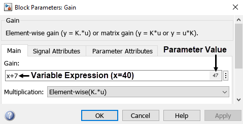
The value of the variable called x is 40. In the Block Parameters dialog box of a Gain block, the text box for entering the Gain value contains the expression "x+7" at the inner left edge, and the number 47 at the right edge.

To see the value the variable or expression has during simulation, run the simulation and open the Block Parameters dialog box or the Property Inspector. The displayed value is the value of the variable or expression in the simulation at the time step when you open the Block Parameters dialog box or the Property Inspector.

When the variable or the expression represents a 1-D or 2-D matrix with four elements or fewer, the values of all the elements are displayed. When the variable or the expression represents a matrix with more than two dimensions or more than four elements, the dimensions and data type of the matrix are displayed instead of the element values.

When the variable or the expression does not represent a numerical matrix, a string, or a character vector, the data type or class is displayed instead of a value. For example, when the variable or expression represents a structure, a cell array, or an object, the data type or class is displayed.

To turn the value display off, in the Simulink Toolstrip, on the Modeling tab, in the Evaluate and Manage section, click Environment, then click Simulink Preferences. Select Editor, then clear Show evaluated value in place.

For more information about the value display, see View Values of Parameters Set as Variables.

Simulink hints panel displays keyboard shortcuts during keyboard selection and signal highlighting

When you are in any of these Simulink modes, you can now view a hints panel that displays keyboard shortcuts specific to the active mode:

  • Selection mode: Use keyboard arrows to change selected block

  • Movement mode: Use keyboard arrows to move selected block

  • Signal highlighting mode: Highlight signal lines between selected block and signal source or destination, and display port values

To see the panel for selection mode, click a block in your model. Press M to switch from movement mode (the default) to selection mode. A panel with shortcuts relevant to keyboard selection appears.
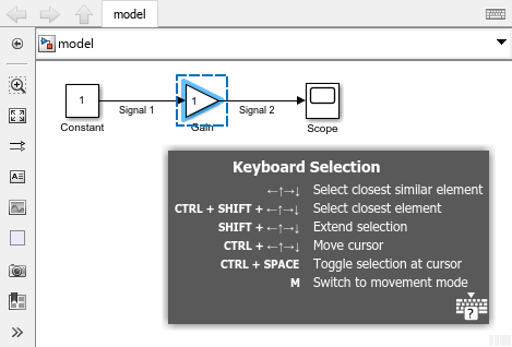
Simulink model with a Gain block selected in movement mode, and the corresponding panel in the bottom right hand corner

To see the panel for movement mode, enter selection mode. Press M to switch to movement mode. The contents of the hints panel change to show keyboard shortcuts relevant to movement mode.
Panel with the title "Keyboard Movement" and shortcuts relevant to movement mode

To see the panel for signal highlighting mode, click a signal in your model. Pause on the ellipsis that appears. In the action menu that expands, click either Highlight Signal to Source Highlight Signal to Source Button or Highlight Signal to Destination Highlight Source to Destination Button. A panel with shortcuts relevant to signal tracing and displaying port values appears.
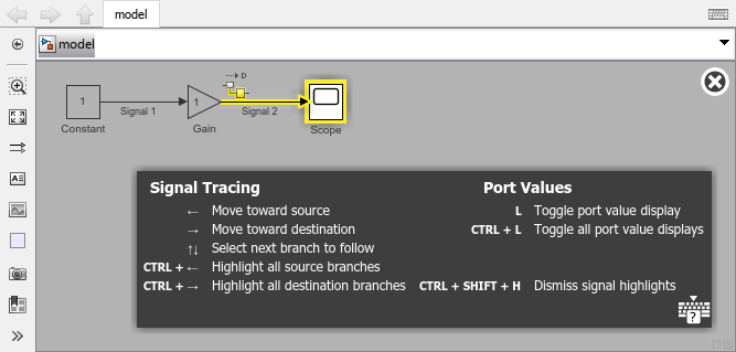
Simulink model with the outbound signal from a Gain block selected, Highlight Signal to Destination active, and the corresponding panel in the bottom right hand corner

To minimize the panel, press ? on your keyboard. When the panel is minimized, only the ? button ? button is visible.

To restore the panel, press ? on your keyboard.

Note

Each type of hints panel preserves its state, minimized or expanded, across MATLAB sessions.

For more information about selection mode, signal highlighting mode, keyboard shortcuts and context-sensitive hints panels, see Use Context-Sensitive Hints Panels to Look Up Keyboard Shortcuts.

Highlight related blocks in referenced model for Simulink Function and Function Caller blocks

When you select a Function Caller block whose related Simulink Function block is in a referenced model, both the Simulink Function block and the Model block of the referenced model are highlighted.
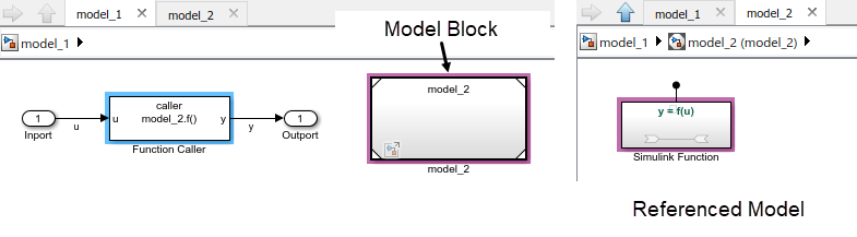
A Simulink model containing a Function Caller block and a Model block are shown on the left, and the contents of the Model block are shown on the right. The Model block contains a Simulink Function block that is related to the Function Caller block. The Function Caller block is selected, and the Model block and the Simulink Function block are highlighted.

If the Simulink Function block is in the model and the related Function Caller block is in the referenced model, both the Function Caller block and the Model block of the referenced model are highlighted when you select the Simulink Function block.

Simulation Analysis and Performance

Zero-crossing detection for code generation

Starting in R2022a, you could enable zero-crossing detection in models that use a fixed-step solver for normal, accelerator, and rapid accelerator simulations. Starting in R2022b, you can generate code for ERT-based system targets from models that use zero-crossing detection with a fixed-step solver, including real-time targets for Simulink Real-Time™ and Simulink Desktop Real-Time™.

New function opens Execution Order viewer

Starting in R2022b, you can programmatically open the Execution Order viewer for a model and highlight a task. For more information, see Simulink.BlockDiagram.getExecutionOrder.

New function to check allowed model changes based on simulation status

The new function slsim.allowedModelChanges returns an indication of the types of changes you can make to a model based on the simulation status.

You can use this function to control the execution of code in callback functions that execute when you simulate a model. For example, you can use this function to ensure mask initialization code that structurally modifies a model executes only before the execution phase.

Signal highlighting enhancement for bus elements

When you select a signal in a model, you can use the Highlight Signal to Source and Highlight Signal to Destination options to trace the propagation of the signal to its source or destination in the model. Starting in R2022a, you could use these options to trace a bus element to its source or destination.

In R2022b, signal highlighting for bus elements is enhanced so you can trace individual signals within a bus hierarchy that have the same name. In R2022a, if you selected a bus element named sine and the bus contained two elements named sine, the Highlight Signal to Source or Highlight Signal to Destination options traced both bus elements. In R2022b, signal highlighting traces only the bus element you select in the Signal Hierarchy Viewer.

For more information about signal tracing, see Highlight Signal Sources and Destinations.

Import custom C and C++ code structures that contain multidimensional arrays

You can now import custom C and C++ code with structures that contain multidimensional array fields in Simulink models. If you pass multidimensional array fields to a custom code function, the function uses row-major array layout automatically. To learn more about implementing C and C++ code in Simulink models, see Implement Algorithms Using C/C++ Code.

Use Visual Studio Code as an external debugger

You can now use Visual Studio Code as an external debugger on Windows, macOS, and Linux platforms. For more information, see Debug Custom C/C++ Code and MATLAB Coder Interface for Visual Studio Code Debugging.

Undefined function handling parameter enhanced and renamed to Undefined function and variable handling

The Undefined function handling configuration parameter has been renamed to Undefined function and variable handling. Change the setting of this parameter to adjust how Simulink checks for undefined functions or variables in C source code files. Before R2022b, the setting of the parameter adjusts how Simulink checks only undefined functions. If your code is not compatible with desktop simulation, or you want to introduce the interface to external code with the relevant header files, set this parameter to Use interface only. See Undefined function and variable handling.

Use sample time offsets for models configured for multicore execution

In R2022b, you can specify offsets for sample times for tasks from the same model component. This functionality allows you to create separate partitions from the same component that are mappable to separate tasks.

In this example, the subsystem has three sample times, 0.1, 1 with offset 0.5, and 1 with offset 0.8. Three partitions from the component are mappable to separate tasks.
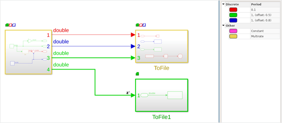
A subsystem with three sample times with three different sample time offsets

Load recorded data into a model using the Playback block

The Playback block, new in R2022b, can load data from the workspace, a file, or the Simulation Data Inspector. Data may be referenced or saved as a copy in the model. The Playback block supports loading data from:

  • Workspace variables of any data format supported by the Simulation Data Inspector

  • MAT files and Microsoft Excel files in the same formats supported by the Record block and the Simulation Data Inspector

  • Custom file formats

The Playback block supports loading real or complex signals with fixed or variable dimensions, discrete and continuous signals, and messages.

After adding data, you can view a sparkline visualization in the Simulink Editor.
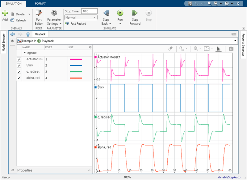
A sparklines visualization in the Playback block.

When working with multiple signals, you can configure the Playback block to have multiple output ports. The Playback block offers flexible port assignments and multirate port-based sample times.

You can configure port properties programmatically or by using the Port Editor. Using the Port Editor allows you to view and configure port properties in one place.
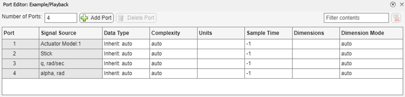
The Port Editor of the Playback block

Once you configure the port properties, you can switch data sets without having to recompile the model.

Toolbar and sidebar responsive to resizing the Simulation Data Inspector

You can now resize the Simulation Data Inspector window without losing menu functionality. When the window becomes smaller than the toolbar or sidebar menu, menu icons move to an overflow menu.
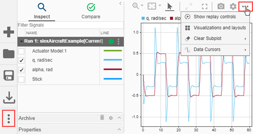
Overflow menus in the Simulation Data Inspector.

Easily discover visualization types in the Simulation Data Inspector

You can easily find the right visualization for your model in the updated Visualizations and layouts menu . Drag a visualization onto a subplot, or click an icon to add the visualization to the active subplot. When you have many subplots, you can still undock the Visualization Gallery to quickly add visualizations.
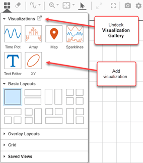
Updated Visualizations and layouts menu.

For more information, see Create Plots Using the Simulation Data Inspector.

Visualization enhancements for the Simulation Data Inspector

Visualizations in the Simulation Data Inspector have several enhancements.

  • You can pause on a subplot to display the name of the visualization type.
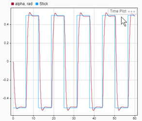
    A time plot with the visualization name now in the upper left corner

  • You can change the limits of the x-axis and y-axis in the XY visualization.
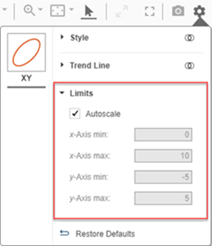
    The Visualization Settings menu for an XY plot showing that the limits can now be changed.

  • Updated map markers distinguish between starting location, destination, and cursor markers. You can also click on a marker to see time, longitude, and latitude data.
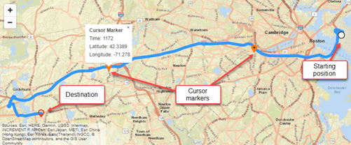
    Enhanced map markers show the starting position, destination, and a cursor at time 1302 for a route from Boston to Natick

    For more information, see View and Replay Map Data.

Scale individual signals in the Simulation Data Inspector and the Record block

You can set the display scale and offset for an individual signal in the Simulation Data Inspector and the Record block. The scale and offset values are automatically saved in the sessions and views of the Simulation Data Inspector. Cursors continue to show the unscaled values. Scaling is not applied when comparing signals.

  • Time plots and sparklines — Scale and offset the display of y values.

  • XY plots — Scale and offset the display of the x values and y variables independently.

  • Array visualizations — Scale and offset the display of each channel in the same manner.

  • Maps — Scale and offset the longitude and latitude independently.

Access comparison results by name

Simplify your workflow by accessing comparison results by baseline signal name using the getResultsByName function. In previous releases, you had to access results by index using the getResultByIndex function.

Load variables into Simulink.SimulationInput object from custom file formats

Starting in R2022b, you can use the loadVariablesFromExternalSource function to specify variables to the Simulink.SimulationInput object from custom file formats. The loadVariablesFromExternalSource function uses a custom file adapter that you can create and register. See Custom file adapter for loading variables from external file formats into Simulink.SimulationInput object. An external source can contain within itself multiple sets of values, for example, an Excel file.

Operating point supported by Simscape blocks in referenced models that simulate in accelerator mode

Starting in R2022b, you can save operating points for a model hierarchy that has a referenced model that simulates in accelerator mode and contains Simscape blocks. The saved operating points, in the form of Simulink.op.ModelOperatingPoint objects, let you step back through the previous states of a simulation.

For more information, see Operating Point Behavior and How Stepping Through a Simulation Works.

Fast restart continues to be unsupported for a model hierarchy with a referenced model that simulates in accelerator mode and contains Simscape blocks.

 Functionality being removed or changed

Simulink no longer supports loading ModelDataLogs data as simulation input

Errors

In R2016a, the ability to log data using the ModelDataLogs format was removed. Since R2021a, a warning occurs when you load existing data stored in the ModelDataLogs format, including Simulink.Timeseries, Simulink.TsArray, and Simulink.SubsysDataLogs data. Starting in R2022b, loading data stored in these formats as simulation input is no longer supported.

Loading data stored using the Dataset format, including MATLAB timeseries objects, is supported. You can convert data stored using the ModelDataLogs format to use the Dataset format using the Simulink.SimulationData.Dataset function.

Simulation Data Inspector no longer computes results when comparing numeric data to strings

Behavior change

Prior to R2022b, you could compare numeric signals to string signals in the Simulation Data Inspector. This action resulted in misleading time plots. Starting in 2022b, if you try to compare numeric data to string data, you receive a message alerting you to the data type mismatch.

Component-Based Modeling

Use local solver in accelerator and rapid accelerator simulations

Starting in R2022a, you could configure a referenced model to use a local solver that is different from the top solver for normal mode simulations. In R2022b, you can use a local solver for accelerator and rapid accelerator simulations.

Trigger model partitions in response to the flow of data into input ports

You can trigger one or more events in a rate-based system based on the flow of data into an input port in the top model or on a model reference interface. Configure event triggers on the Inport or In Bus Element block that represents the port. Then, in the Schedule Editor, specify the partition to execute in response to each event and schedule the priority of execution. By configuring event triggers on input ports, you can model and simulate quality of service effects.

Use the new Execution tab or EventTriggers parameter to add one or more event triggers to an Inport block or In Bus Element block. The event trigger maps an input event to the name of the schedule event it triggers. The table summarizes the event triggers you can configure on input ports.

Input EventInput Event DescriptionEvent Trigger Object
Input writeValue for input port updates.simulink.event.InputWrite
Input write timeoutInput port value does not update within a specified amount of time.simulink.event.InputWriteTimeout
Input write lostInput port value update overwrites unprocessed data.simulink.event.InputWriteLost

 Manage design variations using Variant Manager for Simulink support package

Starting in R2022b, the variant manager functionality is available as a support package named Variant Manager for Simulink. The support package offers these main capabilities:

  • Variant Manager — Visualize the model hierarchy, manage the usage of variant elements across the hierarchy, and create and manage variant configurations.

  • Variant Reducer — Generate a reduced model that contains only selected variant configurations.

  • Variant Analyzer — Compare and contrast variant configurations to identify errors or inconsistencies.

To install the support package, use one of these methods:

  • Open Variant Manager:

    1. In Simulink, on the Modeling tab, open the Design section and click Variant Manager. You can also use any of the alternate methods to open Variant Manager.

    2. In the Install Variant Manager for Simulink dialog box, click Add to install the Variant Manager for Simulink add-on.

  • Use Add-On Explorer:

    1. In MATLAB, on the Home tab, in the Environment section, click Add-Ons and then select Get Add-ons.

    2. In the Add-On Explorer, find and click the Variant Manager for Simulink support package, and click Install.

When you execute any Variant Manager related APIs from the MATLAB Command-Line, the APIs return an error with a hyperlink to launch the installer.

The support package offers new capabilities, enhanced usability, improved workflows, and better scalability for variant management.

New Capabilities
Variant configuration generation

Automatically generate and validate all possible variant configurations for a model.

  • Generate all or the required subset of configurations.

  • Export the configurations to a variant configuration data object. You can export valid configurations for which the model compiles successfully or all configurations including invalid ones.

  • Specify preconditions to restrict the configurations to generate, and optionally export the preconditions as constraints.

Usability Improvements
In-tool usage guidanceGet a quick overview of common workflows upon launch of new Variant Manager.
User interface

  • Easily discover and access capabilities using the new toolstrip based user interface.

  • Use toolstrip buttons to launch the Variant Reducer and Variant Configuration Analyzer apps as separate tabs in the Variant Manager window.

  • Navigate different views of the model hierarchy, organized into separate tabs called System, Blocks, and Stateflow.

  • Search or filter the model hierarchy.

Command-Line APIs

Simulink.VariantConfigurationData class:

  • Specify values of variant control variables using Simulink.VariantControl objects instead of strings.

  • Set properties using name-value arguments instead of positional arguments.

  • Set the PreferredConfiguration property for a model.

Layout preferencesMove, minimize, and restore the toolstrip and other panes in the user interface.
Diagnostic ViewerView information, warnings, and error messages related to variant manager workflows in the embedded Diagnostic Viewer.
ScalabilityExperience improved Variant Manager load time for models with multiple library blocks and referenced models.
Workflow Improvements
Referenced model configurations

  • Maintain consistent definition for a variant control across the model hierarchy. The top-level model must also define the variant control variables used by any referenced components.

  • Use existing referenced model configurations to define corresponding variant control variables in the top-level model configuration using the Component Browser pane.

  • Use a new configuration parameter to specify the diagnostic action to take if top-level model does not use existing referenced model configurations.

Variant Reducer Enhancements
Variant parameters

Reduce variant parameter objects (instance of the Simulink.VariantVariable class) automatically.

Dependent file reduction

Exclude Simulink data dictionary files (*.sldd) and MAT-files (*.mat) outside the MATLAB root folder during reduction.

In the Variant Reducer toolstrip, in the Files to exclude text box, you can specify the full path of the directory or the specific files that must be skipped. When reducing programmatically, you can specify the path of the files using the ExcludeFiles name-value argument.

Variant Semantics Support
Variant Assembly Subsystem blocks

Variant Assembly Subsystem blocks appear in the model hierarchy table.

Inherit from Simulink.VariantControl variant activation time

For variant blocks with Variant activation time set to Inherit from Simulink.VariantControl, the variant manager activation process updates the variant badge for the block in the model hierarchy to indicate the activation time that is computed from the corresponding Simulink.VariantControl variables.

The activation process reports errors for scenarios such as Variant control expression for a block that has undefined variables, has no Simulink.VariantControl variables defined, or combines Simulink.VariantControl variables with conflicting variant activation times.

 Compatibility Considerations

  • Variant Reducer and Variant Analyzer no longer require a Simulink Design Verifier license.

  • The Simulink.VariantConfigurationData and Simulink.VariantManager classes have these changes in the support package:

    Simulink.VariantConfigurationData class

    Removed Functionality

    Recommended Replacement

    DefaultConfiguration propertyPreferredConfiguration property
    SubModelConfigurations property

    The variant configurations for a top-level model must also define the variant control variables used by any referenced components in the model hierarchy.

    validateModel methodSimulink.VariantManager.activateModel method
    getFor methodSimulink.VariantManager.getConfigurationData method
    addSubModelConfigurations methodSimulink.VariantConfigurationData.addComponentConfiguration method
    removeSubModelConfiguration methodSimulink.VariantConfigurationData.removeComponentConfiguration method
    getDefaultConfigurationSimulink.VariantConfigurationData.getPreferredConfiguration
    setDefaultConfigurationNameSimulink.VariantConfigurationData.setPreferredConfiguration

    Simulink.VariantManager class

    New Methods

    Purpose

    Simulink.VariantManager.activateModel Validate and activate a variant configuration on a model.
    Simulink.VariantManager.applyConfigurationApply a variant configuration on a model.
    Simulink.VariantManager.getPreferredConfigurationNameGet the name of the preferred variant configuration for a model.
    Simulink.VariantManager.getConfigurationDataGet the variant configuration data object for a model.

For more information about these changes, see Compatibility Considerations When Using Variant Manager for Simulink Support Package.

For information on the support package, see Variant Manager for Simulink.

Add elements to root input bus element ports without adding blocks or bus objects

Starting in R2022b, you can specify the elements of an input bus at a model interface without In Bus Element blocks to represent each element or a Simulink.Bus object to define the bus hierarchy.

Represent an input bus with an In Bus Element block at the top level of a model. Then, add elements to the input bus with or without adding blocks to the block diagram.

For example:

  1. Double-click an In Bus Element block at the top level of a model.

  2. In the dialog box that opens, select the element that you want to contain a new element.

  3. Click the Add element button arrow , then select Add element without block.

    The new element is nested under the selected element. The block diagram is unchanged.

To programmatically add elements to the input bus without adding blocks to the block diagram, use the new Simulink.Bus.addElementToPort function.

Programmatically set element properties at bus element ports

Starting in R2022b, you can programmatically get and set properties of elements of In Bus Element and Out Bus Element blocks with the get_param and set_param functions, respectively.

For example, consider a model named mymodel with a subsystem named Subsystem1. The subsystem contains an Out Bus Element block that corresponds to a bus named Out1. The bus has a nested bus named nonsinusoidal that contains an element named saw.

In the MATLAB Command Window, get the data type of this element with the get_param function.

get_param('mymodel/Subsystem1/Out1.nonsinusoidal.saw','OutDataTypeStr')
ans =

    'Inherit: auto'

Suppose you want the data type of the element to be single. Set the data type to single with the set_param function.

set_param('mymodel/Subsystem1/Out1.nonsinusoidal.saw','OutDataTypeStr','single');

Referenced models in accelerator mode with variable-step solvers support noninlined S-functions

Starting in R2022b, referenced models that simulate in accelerator mode and use variable-step solvers can use noninlined S-functions.

For information about using S-functions with referenced models, see Model Reference Requirements and Limitations.

Use Message Triggered Subsystem block in rate-based models to schedule execution order and model asynchronous behavior

In R2022b, you can use the Message Triggered Subsystem block in rate-based models when you use the block in scheduled mode. Scheduled mode allows you to specify the execution order of the subsystem in the Schedule Editor to model asynchronous behavior.

In a rate-based model, you can connect your root Inport block to a Message Triggered Subsystem block in a rate-based model. The message-triggered subsystem is triggered externally while other parts of the model run periodically.

Asynchronous simulation of client-server interfaces

Starting in R2022b, asynchronous simulation is supported for client-server interfaces.

When you enable asynchronous client-server semantics, Function Caller blocks have a message output port for all output arguments. The caller (client) makes a request to call the function (server). The function is executed based on the ordering defined in the Schedule Editor and then returns the output arguments to the caller. The block outputs these arguments using a message output port.

  • If there is one function output argument, the output argument becomes the message payload.

  • If there is more than one function output argument, the Function Caller block bundles the output arguments as a structure that becomes the message payload.

The message output port must connect to a Message Triggered Subsystem. The Message Triggered Subsystem acts as a callback for the function.
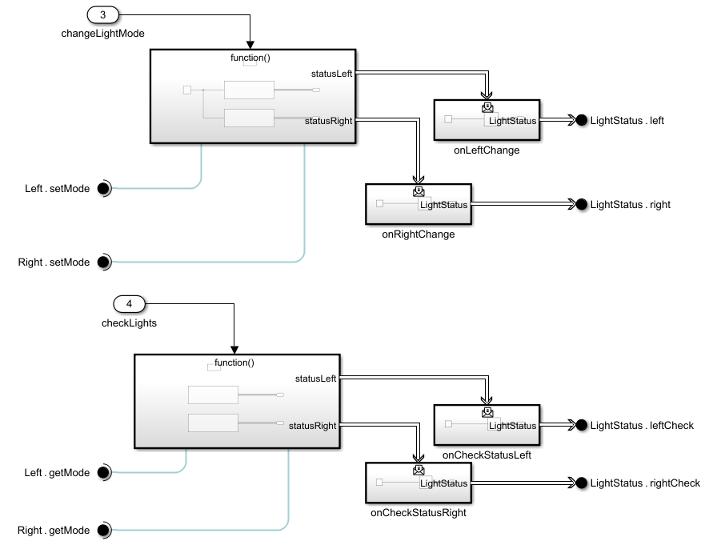
Asynchronous simulation with two Function Caller blocks with two Message Triggered Subsystem blocks each.

For more information, see Call Simulink Functions in Other Models Using Function Ports.

Half-precision data type support for MATLAB System block

Starting in R2022b, the MATLAB System block supports the half-precision data type for block input, output, state, and parameter values. You can also use code generation to deploy half-precision algorithms developed using the MATLAB System block. For R2022b, the block does not support complex values for half-precision data types.

Simulate and generate code from a model with conditionally executed subsystem types as choices to a Variant Subsystem

Starting in R2022b, you can add control port blocks such as Enable, Trigger, Reset, or Function-Call port blocks to a Variant Subsystem whose choices are conditionally executed systems. While naming the ports:

  • For Variant Subsystems with update diagram analyze all choices, code compile or startup as the activation time, all the choice blocks must have the control port blocks and all control port names match.

  • For Variant Subsystems with update diagram as the activation time, the active choice must have a matching control port.

For more information, see Use Variant Subsystem Blocks with Conditionally Executed Subsystems.

Create real-time applications using Variants and Simulink Real-Time in External Mode with startup activation

Starting in R2022b, you can create real-time applications models containing Variant blocks, with the Variant activation time set to startup, that can run on target computer hardware connected to your physical system in the External Mode. For more information, Create Real-Time Applications Using Variants and Simulink Real-Time.

Export and import a model with Variant blocks as a standalone FMU

Starting in R2022b, you can export models with inline variant blocks, and variant subsystems to a standalone Functional Mock-up Unit (FMU). The Variant activation time of the variant blocks must be set to startup. You can also import an existing FMU by using the FMU block. For more information, see Export and Import Function Mockup Unit (FMU) from Model with Variant Subsystem Blocks.

Use MATLAB structure elements as variant control variables to improve readability of generated code with all variant activation times

Starting in R2022b, you can use MATLAB structure elements as variant control variables in the variant control expression for generating code with update diagram analyze all choices, code compile, and startup variant activation times. This allows you to group the related variant control variables as elements of a MATLAB structure, which can be used in the variant control expressions to generate readable code. For more information, see Structures to Group Related Variant Control Variables of Variant Blocks.

Configure variant choice without opening or modifying the model using Variant Assembly mode

Starting in R2022b, use the Variant Assembly mode of the Variant Subsystem block to add or remove a model or subsystem reference file externally located in a folder or network as a variant choice without having to open the block or modify the model. Variant assembly mode allows you to add or remove variants without having to navigate into the Variant Subsystem block or dirtying the model.

To add a model or a subsystem reference file as a new variant choice, specify a MATLAB expression that returns a cell array of model or subsystem file names in the Variant choices specifier parameter located in the Reference tab of the Block Parameters dialog box. You can switch between different variant choices using the label mode.

For more information, see Add or Remove Variant Choices of Variant Assembly Subsystem Blocks Using External Files.

Inherit activation time of Simulink.VariantControl object used in a Variant block

Starting in R2022b, you can inherit the activation time of the Simulink.VariantControl object used in a Variant Source, Variant Sink, or a Variant Subsystem block as the variant activation time of that block. This allows you to easily switch between different variant activation times of the blocks and switch models from rapid prototyping workflows to production code generation or vice versa. To inherit the activation time of the Simulink.VariantControl object, select inherit from Simulink.VariantControl as the variant activation time. For more information, see Simulink.VariantControl Variables for Coherent Switching of Choices in Variant Blocks.

Use normal MATLAB variables in variant control expression for variant blocks with startup variant activation time for inline parameter

Starting in R2022b, you can use normal MATLAB variables in the variant control expression for variant blocks whose variant activation time is startup for inline parameter behavior. You can use a normal MATLAB variable directly in the variant control expression or as a condition expression with normal MATLAB variables of type Simulink.Variant object.

Generate HDL code with all Variant Choices from Variant Subsystem

Starting in R2022b, you can generate HDL code that contains both active and inactive choices of a Variant Subsystem block. In the generated HDL code, the variant control variable is a tunable port. You can set the active choice by providing the value of the variant control variable at the model startup. For more information, see Variant Subsystem: Using Variant Subsystems for HDL Code Generation (HDL Coder).

The function name of the Simulink Function block supports more than 63 characters

Starting in R2022b, the name of a Simulink function is a valid ANSI® C identifier and can exceed 63 characters. For more information, see Simulink Functions Overview.

Improved mask parameter constraint definition

You can now select multiple data types in the Data Type property for validating the parameter value. To validate the parameter value against a specific range, use the Minimum and Maximum properties because the Data Type property does not validate the parameter value against the range.

For example, to validate the parameter value against the data type numeric and range 0 - 127, use the definition shown in the following figure.
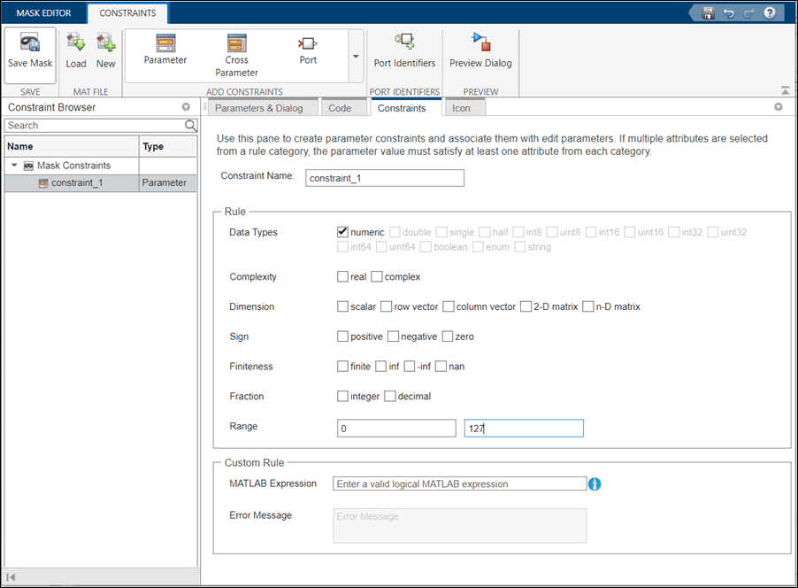
mask parameter constraint

For more information on parameter constraint definition, see Validating Mask Parameters Using Constraints

 Functionality being removed or changed

Variants argument of find_system and find_mdlrefs functions will be removed

Warns

The Variants argument will be removed from the find_system and find_mdlrefs functions in a future release.

  • When you use the find_system function without specifying the Variants argument, the function includes only active Variant Subsystem blocks in the search.

  • When you use the find_mdlrefs function without specifying the Variants argument, the function includes Variant Subsystem blocks that are active in simulation or code generation in the search.

Starting in R2022b:

  • When you use the find_system and find_mdlrefs functions without the Variants argument, the functions generate a warning if they skip the inactive choices of a Variant Subsystem block during the search.

  • When you use these functions with the Variants argument value set to 'AllVariants', the functions generate a warning.

For examples and more information on the removal of Variants argument, see Compatibility Considerations.

Project and File Management

Design Evolution Manager: Model and manage your engineering process in MATLAB Online

Use the Design Evolution Manager to help you model and analyze your engineering process. A design evolution is a snapshot of all files included in a project. When developing a new design or troubleshooting an existing design, you may add or remove files from the design or create different versions of files in your design. By creating evolutions at key stages in your design process, you can manage and compare different versions of a design during the course of your work. The relationships between evolutions and the metadata associated with evolutions help you to understand the big-picture trajectory of your design process, including why certain design decisions were made. For an example, see Use Design Evolution Manager with the Fixed-Point Tool.
Screenshot of Design Evolution Manager showing an evolution tree.

The Design Evolution Manager is available on MATLAB Online only.

Project API: Extract project from archive

You can now extract a project from an archive by using matlab.project.extractProject.

Dependency Analyzer: New warnings to identify problems

When you run a dependency analysis, the Dependency Analyzer now warns about models that you created in a newer release, files that contain a syntax error, and files that have a .slx extension but are not valid Simulink models. See Check Dependency Results and Resolve Problems.

Dependency Analyzer: Analyze and view dependencies of MATLAB action language

You can now view and analyze the dependencies of MATLAB action language in Stateflow states and transitions. The Dependency Analyzer also displays external function calls in the dependency graph of a project or a model. The Dependency Analyzer supports Stateflow charts, Test Sequence, and Test Assessment blocks.

Source Control in MATLAB Online: Manage Git branches and repositories

You can now manage Git branches and repositories in MATLAB Online:

  • Create, switch, merge, and delete branches.

  • Find and compare commits.

  • Create branches from a tag or a revision.

  • View the history of a Git repository.

  • Manage multiple Git repositories at once.

Model Comparison: Automatically attach comparison reports to pull requests using GitHub Actions

This topic shows how to automate the generation of Simulink model diffs for GitHub pull requests and push events using GitHub Actions. Download and use the provided files to automatically attach the comparison reports to the pull request or push event for easy viewing outside of MATLAB and Simulink. For more information, see Simulink Model Comparison for GitHub Pull Requests and watch Simulink Model Comparison for GitHub Pull Requests (4min 46sec).

Model Comparison: Generate comparison reports on a no-display computer

You can now generate comparison reports when you run MATLAB on a no-display machine. This is particularly useful for continuous integration (CI) workflows, which frequently use headless systems such as GitHub and GitLab runners. Comparison reports generated using a no-display MATLAB session do not contain screenshots. For more information about generating model comparison reports for continuous integration workflows, see Simulink Model Comparison for GitHub Pull Requests.

Comparison Tool: Compare MAT and FIG files in MATLAB Online

Starting in R2022b, you can compare MAT and FIG files in MATLAB Online.

You can access the comparison tool from:

  • The MATLAB Current Folder browser context menu

  • The Current Project browser context menu

  • The MATLAB Command Window using the visdiff function

Project Examples: Organize projects into components using references and Git submodules

This example shows how to create a new component from an existing project folder. It also shows how to use other projects as referenced projects. For a project under Git source control, the example demonstrates how to populate a reference project by using Git submodules. See Organize Projects into Components Using References and Git Submodules.

Data Management

Type Editor lets you manage alias, numeric, enumerated, and value types

The Type Editor is an upgraded version of the Bus Editor that lets you manage these objects in the base workspace and data dictionaries:

  • Simulink.AliasType

  • Simulink.NumericType

  • Simulink.data.dictionary.EnumTypeDefinition (data dictionaries only)

  • Simulink.ValueType

The Type Editor continues to support these objects:

  • Simulink.Bus

  • Simulink.BusElement

  • Simulink.ConnectionBus

  • Simulink.ConnectionElement

For more information, see Type Editor.

Create signals with Live Editor

Use the new Create Signal task to quickly create signal data. The task also automatically generates code that becomes part of your live script.

To add the Create Signal task to a live script in the MATLAB Editor:

  • On the Live Editor tab, select Task > Create Signal.

  • In a code block in the script, type a relevant keyword, such as create signal, vector, timeseries, timetable, input, signal, or source. From the completed command completions, select Create Signal from the suggested command completions.

For more information about Live Editor tasks, see Add Interactive Tasks to a Live Script.

Root Inport Mapper updates

The Root Inport Mapper has these updates:

  • These changes have been made to the look and feel of the Root Inport Mapper toolstrip:

    • The Map to Model section is renamed Map Configuration. In Map Configuration:

      • The map modes are now available in the Map Mode list.

      • Update Model is now Update Model Automatically.

      • Allow Partial is now Allow Partial Specification of Buses.

    • The Map to Model list is now Check Map Readiness.

    • Mark for Simulation is now Apply to Model.

    • In the Script section, Generate MATLAB Script and Run Script are now combined in Generate Script, which generates the batch simulation file and opens it in MATLAB Editor.

  • Mark for mapping scenario has changed to automatically mark the first scenario to map. In earlier releases, you selected a scenario to be mapped.

  • Keyboard shortcuts are now available for Root Inport Mapper actions. For more information, see Root Inport Mapper Keyboard Shortcuts.

Signal Editor updates

The Signal Editor tool has these updates. For more information, see Create and Edit Signal Data.

  • The Insert section has been reorganized:

    • As in previous releases, to add basic signals, select Signal, Bus, Function Call, and Ground. To add custom signals, select Author Signal or Draw Signal.

      Signal Editor list of quick signals to add, including basic signal, bus, function call, and ground. Signal Editor list of custom signals using Author Signal or Draw Signal.

    • To get more detailed information on the signals, click the expander.
      Signal Editor Insert section drop-down list of signal actions.

      • To add basic signals, select Signal, Bus, Function Call, and Ground.

      • To add custom signals, select Author Signal or Draw Signal.

      • To add standard waveforms, select:

        • Constant — Straight line waveform with a default value of 1.

        • Step — Step waveform with default initial value of 0 and final value of 5.

        • Pulse — Pulse waveform with default initial value of 0, pulse at trigger 5, and pulse duration of 1.

        • To configure the signal properties, including those for the waveforms, click the Defaults button Signal Editor Defaults button..

  • The Signal Editor supports accessing and evaluating variables in the model workspace and data dictionary workspace. In previous releases, Signal Editor supported the access and evaluation of variables in only the base workspace.

Custom file adapter for loading variables from external file formats into Simulink.SimulationInput object

In R2022b, you can create and register a custom file adapter that the loadVariablesFromExternalSource function can use to load variables from a custom external source file format into a Simulink.SimulationInput object.

To write a custom file adapter, create a new class that derives from the Simulink.data.adapters.BaseMatlabFileAdapter base class. Then implement these required functions:

  • getAdapterName — Returns the display name for the adapter

  • getSupportedExtensions — Returns the valid source file extensions that the adapter supports

  • getData — Loads data from the external file into a data source workspace

For example, suppose you have the following XML file.

<customerData>​
  <var1>10</var1>​
  <var2>15</var2>​
</customerData>

You can write a custom file adapter similar to the following:

classdef xml_adapter < Simulink.data.adapters.BaseMatlabFileAdapter​
    methods​
        function name = getAdapterName(~)​
            name = ‘XML Adapter’;​
        end​

        function extensions = getSupportedExtensions(~)​
            extensions = {‘.XML’ };​
        end​

        function diagnostic = getData(this, sourceWorkspace, ~, diagnostic)​
            % Every time getData is called on the same source, sourceWorkspace is the same as ​
            % the last time it was called.  Clear it to make sure no old variables exist.​
            clearAllVariables(sourceWorkspace);​
            dom = xmlread(this.source);​
            tree = dom.getFirstChild;​
            if tree.hasChildNodes​
                item = tree.getFirstChild;​
                while ~isempty(item)​
                    name = item.getNodeName.toCharArray';​
                    if isvarname(name)​
                        value = item.getTextContent;​
                        setVariable(sourceWorkspace, name, str2num(value)); %#ok<ST2NM> ​
                    end​
                    item = item.getNextSibling;​
                end​
            end​
        end​
    end​
end​

For further customization of your adapter, the base class also includes optional functions that you can override. For example, you can write a function to validate a file or to define logical divisions for the data in the file.

Register your custom adapter in a startup script for each MATLAB session so that it is available on the MATLAB path. To register your adapter, use the Simulink.data.adapters.registerAdapter function.

When an external source is requested, the adapter manager creates a new instance of the custom adapter and manages it until the external source is no longer needed.

For more information on writing a custom file adapter, see Create External File Adapter for Loading Variables into Simulink.SimulationInput Object.

For more information on using the custom file adapter to load variables into a Simulink.SimulationInput object, see Load variables into Simulink.SimulationInput object from custom file formats.

Updates for model parameter EnforceDataConsistency

In R2022a, the model parameter EnforceDataConsistency was added to provide the option to relax data consistency checking across model hierarchies. When the parameter is set to off, the current model and the models below it in the model hierarchy can use symbols with the same name but different values as long as each model in the hierarchy can see only one definition of the symbol.

In R2022b, the parameter has these updates:

  • Setting the parameter to off no longer results in errors during simulation of a model hierarchy that contains one or more models running in Accelerator or Rapid Accelerator mode.

  • In addition to using the set_param function to set EnforceDataconsistency, you can now also set the parameter in the Model Properties dialog box. On the External Data tab, select or clear the Enforce consistent data definitions across referenced models check box.

For more information, see Considerations Before Migrating to Data Dictionary.

Simulink.LookupTable objects support differently sized tables and breakpoints

Simulink.LookupTable objects now support differently sized tables and breakpoints that have the same structure type.

To enable a model with two blocks containing these objects to simulate, select the Allow multiple instances of this type to have different table and breakpoint sizes check box. For code generation with Simulink Coder, the software generates a common struct type with pointer typed member fields for the two objects to represent the table and breakpoint data.

To support this capability, the Simulink.LookupTable class has these updates:

  • The Support tunable size property has been moved to the new Advanced tab.

  • To configure a Lookup Table object to support differently sized tables and breakpoints, select the new Allow multiple instances of this type to have different table and breakpoint sizes check box.

Block Enhancements

Model loop delay, latency, and pulse delay using new Propagation Delay block

The new Propagation Delay block in the Discrete library delays the current value for a signal into the future by an amount specified by a delay signal. The Propagation Delay block is well suited for implementing time delay in a discrete system.

Schedule time step for variable-step solver using new Hit Scheduler block

Using the new Hit Scheduler block, you can schedule major time steps for a variable-step solver based on the behavior of your model during simulation. The block stores the time hits in a queue until the simulation reaches each scheduled time.

You can configure the Hit Scheduler block to produce either a signal output or a function-call output.

The Hit Scheduler block supports only scalar inputs and does not support fixed-step solvers.

Perform image processing tasks using new Neighborhood Processing Subsystem block

Use the Neighborhood Processing Subsystem block to create applications that follow the neighborhood pattern. The block calculates each output element by applying an algorithm on the adjacent neighborhood elements of each input element. Use the Neighborhood Processing Subsystem block for image processing tasks such as edge detection.

Specify sample time for C Caller and C Function blocks

You can specify the Sample time parameter for C Function and C Caller blocks. By default, the blocks inherit sample time. See Types of Sample Time and Specify Sample Time.

Additional support for C Function blocks

The C Function block now supports:

  • C++ functions that use bool types

  • Class methods with pass-by-reference or return-by-reference arguments

From Spreadsheet block update

The From Spreadsheet block reads data from Microsoft Excel (all platforms) or CSV (only Microsoft Windows platforms with Microsoft Office installed) spreadsheets and outputs the data as a signal. By default, the From Spreadsheet block reads spreadsheets using the Component Object Model (COM) interface on Windows platforms and the LibXL library on other platforms. If the From Spreadsheet block has a problem reading the spreadsheet on Windows, use the set_param function to set 'ReaderLibrary' to 'LibXL'.

Saturation Dynamic block can inherit output data type from driving block

The Saturation Dynamic block can now inherit the output data type from a driving block

Transfer Fcn Lead or Lag block supports single data type for poles and zeroes

The Transfer Fcn Lead or Lag block now supports the single data type for the Pole of compensator (in Z plane) and Zero of compensator (in Z plane) parameters.

Lookup Table Editor support for lookup table control

In the Lookup Table Editor, view and edit variables or parameters that the Lookup Table Control uses as lookup tables:

  • If you specify lookup table controls on your lookup table block, the lookup table data described by the lookup table controls are visible and editable in the Lookup Table Editor, as they are in the mask dialog. This capability makes the lookup table data visible and editable in a spreadsheet in both the block mask dialog and Lookup Table Editor. The Lookup Table Editor no longer needs to maintain a separate global registration for custom lookup table blocks. In previous releases, to view lookup table data used by custom lookup table blocks, you had to register the block for the Lookup Table Editor using Register Custom. For more information, see Visualize Lookup Tables Visualized Through Lookup Table Control.

  • If you specify lookup table controls for arguments on the mask of referenced models, you can now edit instance-specific lookup table data for those referenced models in the Lookup Table Editor.

Lookup Table Editor support for MATLAB structures

The Lookup Table Editor now overwrites expressions set in the block dialog unless an expression is a pure structure field reference. For example, if the expression myDataSet.MyLookupTable.Breakpoints is set as the parameter value, the Lookup Table Editor updates the value of myDataSet.

In previous releases, Lookup Table Editor overwrote the string set in the block dialog even if the string set was a pure structure field reference.

String blocks support code generation for row-major array layout

String blocks now support code generation for row-major array layout.

Evaluate Variables and MATLAB Expressions in a Custom Table Mask Parameter

Use the Evaluate column property to evaluate any MATLAB expressions that you input to a custom table from the mask dialog of a Simulink block.

Consider a masked Subsystem block that has a custom table mask parameter. The Evaluate property of a column named Sample Time is enabled. When you specify a MATLAB expression in the Sample Time column, Simulink evaluates the expression and uses the result of the calculation. If you disable the Evaluate property of the Sample Time column, Simulink takes a literal reading of the expression as you type it in the mask dialog.

You can enable the Evaluate property in two ways.

View Custom Table Mask Parameter as a Cell Array

A custom table mask parameter is now generated as a cell array variable in the mask workspace. In previous releases, a custom table parameter was a plain character vector or a string variable.

Customize System Object Dialog Using Mask Editor

Starting in R2022b, use Mask Editor to customize dialogs for System objects. This method saves time in writing code for dialog customization. You can launch Mask Editor from the System Object tab.
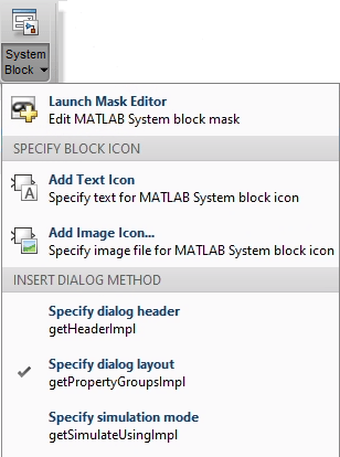
System object customization using mask editor

All the existing and new customizations will be saved in a new .xml file and the getPropertyGroupsImpl function will be removed. For more information, see Customize System Object Dialog Box Using Mask Editor.

Create a new block icon or modify existing ones using Graphical Icon Editor

  • Interactive graphical environment: Use graphical tools like pen, curvature, text, scissor, connector, and equation (which supports LaTeX) to create rich graphical icons. Grids, smart guides, and rulers help you to create pixel-perfect icons. Apart from the drawing tools, a few built-in shapes, such as Resistor, Inductor, and Rotational Damper, are readily available
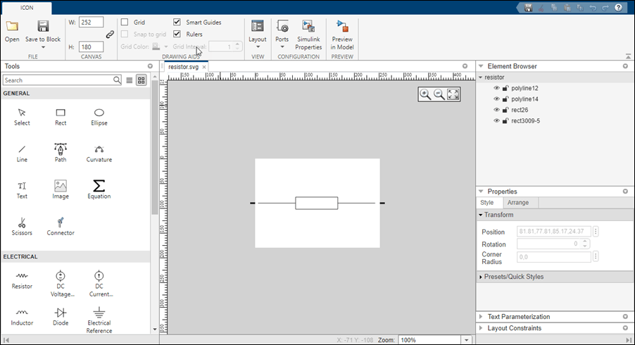
    block icon editor

  • Element browser: Element browser lists all the elements in the icon.

    • Hide or unhide an element in the icon.

    • Lock or unlock an element so that you do not accidentally change the shape or position of an element while working on other elements of the icon.

    • Name each element in the icon for easy identification.

  • Port binding/unbinding: The number of ports on each block is pre-defined if you are creating or modifying the block using block context. For example, the number of ports for Simscape blocks or Aerospace blocks are pre-defined and they appear on the block icon. You can also define the number of ports on the block icon if you are creating or modifying a block without a block context.

  • Conditional visibility: Hide or unhide an element of the block based on the block parameters.

  • Preview options: Preview the icon in Simulink using preview options such as horizontal stretch, flip, or scale. You can also preview the icons with modified block parameters.

  • Display elements that fit the size of the icon: The first-fit feature helps you to display only the elements that fit in the size of the icon when you resize the block.

  • Position elements relatively: The auto layout constraint feature helps you to position each element relative to other elements on the canvas.

For more information on Graphical Icon Editor, see Create and Edit Masked Block Icon Using Graphical Icon Editor

Undo and redo support for customizable dashboard blocks in panel

You can now undo and redo the changes you make to customizable dashboard blocks that are in a panel.

To undo or redo a change:

  1. Click the panel or a block in the panel.

  2. Press Ctrl+Z to undo the change, or press Ctrl+Y to redo the change.

Note

The keyboard shortcuts are based on Windows. On a Mac, press command (⌘) instead of Ctrl.

Toolstrip support for panels

You can now use the Simulink Toolstrip to manage and edit panels and the dashboard blocks that they contain.

When you click a dashboard block in a panel, the toolstrip tab for the block appears. For example, when you click a Circular Gauge block, the Gauge tab appears in the toolstrip.
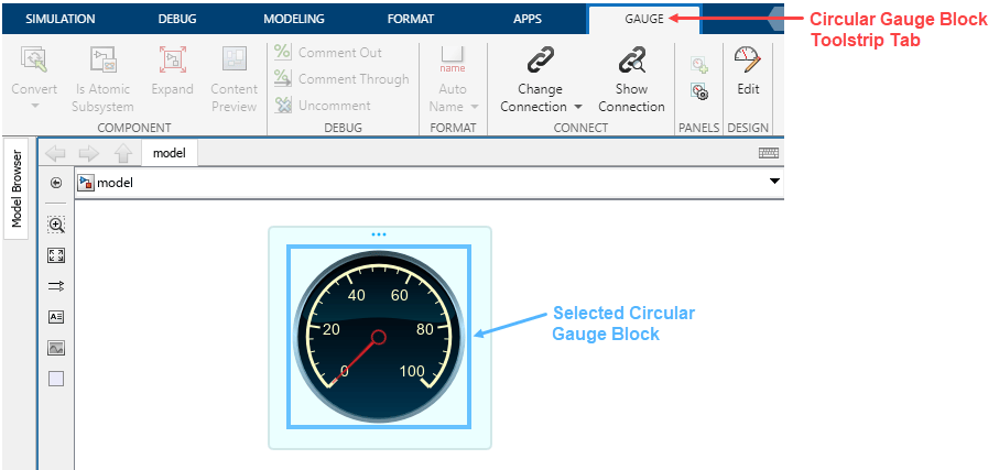
A Circular Gauge block is selected in a panel, and the Simulink Toolstrip shows the Gauge tab.

When you click a panel, the Panel tab appears in the toolstrip. The tab provides these options:

  • To manage the visibility of panels in the model, in the Manage section of the Simulink Toolstrip, click Manage Panels. The Manage Panels dialog box opens and displays an icon for each panel in the model. You can use the dialog box to change the visibility of panels:

    • To hide a panel, click the icon of the panel in the dialog box.

    • To unhide the panel, click the icon of the panel in the dialog box again.

    For more information on the Manage Panels dialog box, see Interactively Design and Debug Models Using Panels.
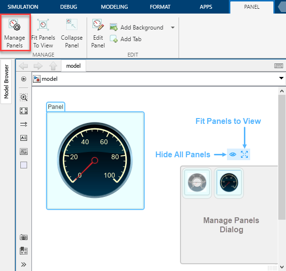
    A panel that contains a Circular Gauge block is selected, and the Panel toolstrip tab is shown. In the Panel toolstrip tab, the Manage Panels button is boxed in red, and in the canvas, the Manage Panels dialog is open. While only one panel is visible in the Simulink window, the dialog shows two panels: the panel that contains the Circular Gauge block, and a second panel that contains a Knob block. Above the Manage Panels dialog, the Hide All Panels and Fit Panels to View buttons are labeled.

  • To fit all non-hidden panels within the current view, in the Manage section of the Simulink Toolstrip, click Fit Panels to View.
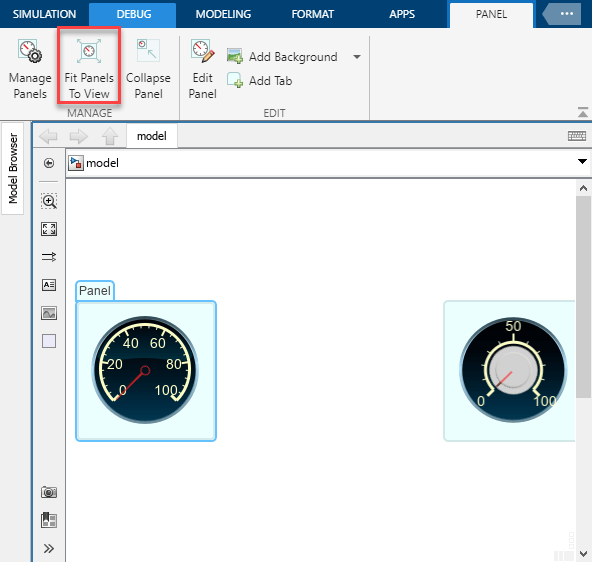
    The same model is shown again, except that now the Fit Panels To View button is boxed in red, and both the panel that contains the Circular Gauge block and the panel that contains the Knob block are visible in the canvas.

  • To collapse the selected panel, in the Manage section of the Simulink Toolstrip, click Collapse Panel.
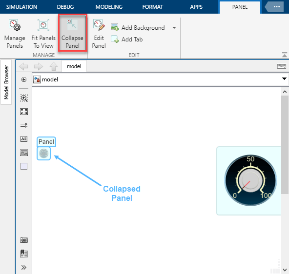
    The same model is shown again, except that now the Collapse Panel button is boxed in red, and the panel that contains the Circular Gauge block is collapsed into a small blue square.

  • To customize the size and the contents of the panel, in the Edit section of the Simulink Toolstrip, click Edit Panel. The panel action menu appears over the selected panel, with multiple options for editing panels:

    • To change the background image of the panel to a custom image, click Change Background Image Change Background Image button.

    • To move the selected panel behind all other panels that overlap it, click Send to Back Send to Back button.

    • To move the selected panel in front of all other panels that overlap it, click Bring to Front Bring to Front.

    • To add a tab to the panel, click Add Tab Add Tab.

    • To delete the selected tab, or the panel if it has only one tab, click Delete Panel Delete Panel button.

    • To stop editing the panel, click Done Editing Done Editing button. Alternatively, in the Simulink Toolstrip, click Edit Panel.
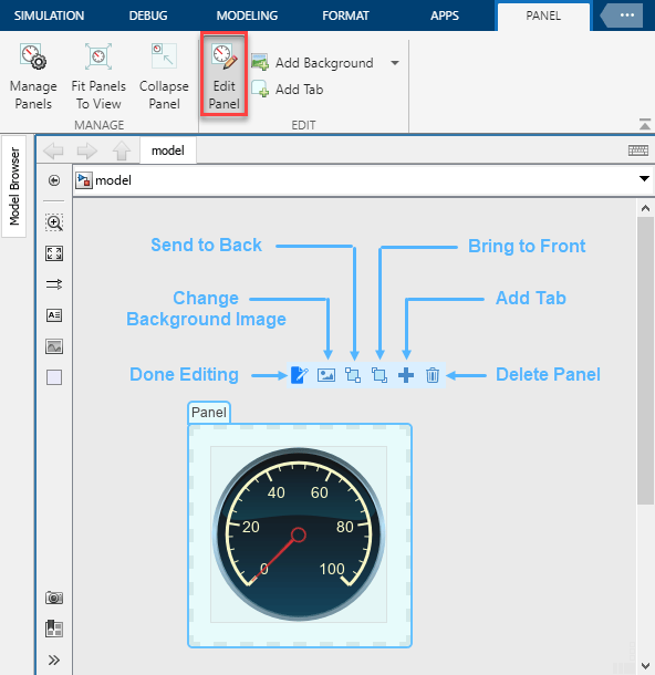
    A panel that contains a Circular Gauge block is shown in edit mode. In the Simulink Toolstrip, the Edit Panel button is boxed in red. The action menu is visible, with the buttons labeled. In order from left to right, the buttons are: the Done Editing button, the Change Background Image button, the Send to Back button, the Bring to Front button, the Add Tab button, and the Delete Panel button.

  • To set a custom background image for the selected panel, in the Edit section of the Simulink Toolstrip, click Add Background.

  • To add a new tab to the selected panel, in the Edit section of the Simulink Toolstrip, click Add Tab.
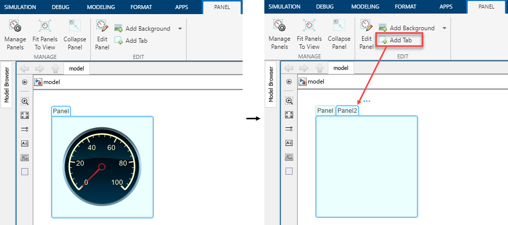
    The left image shows a panel with a single tab labeled Panel. The tab contains a Circular Gauge block. The right image shows the same model, with the Add Tab button in the Panel tab of the Simulink Toolstrip boxed in red. In the canvas, there is a panel with two tabs, respectively labeled Panel and Panel2. Panel2 is open and empty.

Reset Function block supports blocks with states, MATLAB Function blocks, and Stateflow charts

Starting in R2022b, the Reset Function block can contain:

  • Blocks with states, such as Unit Delay blocks

  • MATLAB Function blocks with or without persistent or global data

  • Stateflow charts

For more information, see Initialize, Reinitialize, Reset, and Terminate Function Limitations.

Subsystem references support Reinitialize Function blocks

Starting in R2022b, you can have Reinitialize Function blocks in referenced subsystems that use reinitialize event ports. To display reinitialize event ports on a Subsystem block, select the Show subsystem reinitialize ports block parameter.

For information about referenced subsystems, see Subsystem Reference.

PWM block supports initial delay

Starting in R2022b, you can set the Initial Delay parameter of the PWM block to provide a phase delay. You can add a phase delay to the generated PWM signal.

Parameter Writer block supports more blocks

Starting in R2022b, you can use the Parameter Writer block to write to these blocks:

  • State-Space block

  • Discrete State-Space block

  • Integrator block

  • Second-Order Integrator block

  • Pulse Generator block

  • Discrete Pulse Generator block

  • Sine Wave block

  • Signal Generator block

  • Step block

  • Bias block

  • Polynomial block

  • Switch block

  • Rate Limiter block

  • Dead Zone block

  • Real-Imag To Complex block

  • Quantizer block

  • Backlash block

  • Random Number block

  • Transport Delay block

  • Variable Transport Delay block

PID Controller Blocks: Option to provide integrator saturation limits

PID controller Simulink blocks now let you specify upper and lower integrator saturation limits. Doing so allows you to limit the integrator output to be within a specified range. When the integrator output reaches the limits, the integral action turns off to prevent integral windup.

To specify the integrator saturation limits, in the block parameters, on the Saturation tab, under Integrator saturation, enable Limit output, then specify the limits using the Upper limit and Lower limit parameters.
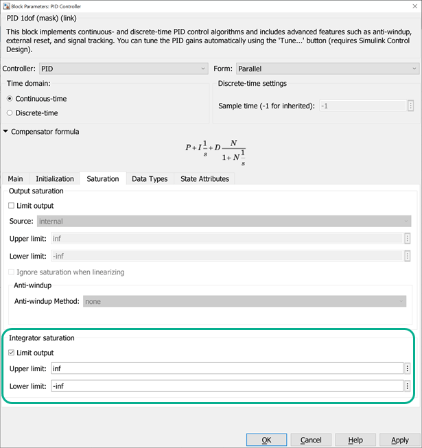
PID Controller block parameters dialog.

Enable MATLAB System block to support 1-D input and output signals

Starting in R2022b, use the supports1DVectorsImpl method to enable the MATLAB System block to recognize and propagate vectors inputs and outputs as 1-D.

 Functionality being removed or changed

Programmatically saving models containing Signal Builder block to releases prior to R2014b no longer supported

Behavior change

Programmatically saving models that contain Signal Builder blocks to releases from R2014b and earlier is no longer supported. Programmatic saving methods include:

Opening these resaved models causes MATLAB to crash.

Interpreted MATLAB Function block removal

Still runs

The Interpreted MATLAB Function block will be removed in a future release.

PID Controller blocks issue error when integrator and filter initial conditions lie outside saturation limits

Behavior change

Starting in R2022b, PID Controller blocks issue an error when the integrator or filter initial condition value lies outside the output saturation limits. In previous releases, these blocks did not issue an error when these initial conditions had such values.

If this change impacts your model, update the PID integrator or filter initial condition values such that they are within the output saturation limits.

Connection to Hardware

Extended support for customizable Dashboard blocks on Android devices

The Simulink Support Package for Android Devices now supports deploying these customizable Dashboard blocks on your Android device.

Rotary SwitchRocker Switch
Toggle SwitchSlider Switch
Horizontal GaugeVertical Gauge
Vertical SliderHorizontal Slider
Push ButtonLamp

You can customize the visual aspects of these Dashboard blocks in a Simulink model and obtain the what you see is what you get (WYSIWYG) visualization on your Android device as well as on web pages. Earlier, the support package supported only the customizable Gauge and Knob Dashboard blocks.

Support added for Bluetooth communication on Arduino compatible ESP32-WROOM boards

The Simulink Support Package for Arduino Hardware now supports deploying a Simulink model containing BLE Send and BLE Receive blocks on Arduino compatible ESP32-WROOM boards. You can now send and receive data using the Bluetooth low energy (BLE) protocol on your Arduino compatible ESP32-WROOM boards.

Configure baud rate and serial communication parameters for Arduino boards

The Simulink Support Package for Arduino Hardware now supports configuring serial communication parameters such as number of data bits, parity, and number of stop bits on Arduino boards. You can also enter the custom baud rate over serial communication pins that require a particular baud rate.

Support added for Arduino compatible ESP32-WROVER boards

The Simulink Support Package for Arduino Hardware now supports deploying Simulink models on the ESP32-WROVER boards. The Hardware board drop-down list in the Configuration Parameters dialog box now displays the ESP32-WROVER (Arduino Compatible) option.

The support package also provides real-time execution profiling for Simulink models deployed on the ESP32-WROVER boards.

Publish and subscribe to messages using MQTT communication protocol on Arduino boards

With the addition of the Wi-Fi MQTT Subscribe and Wi-Fi MQTT Publish blocks to the Simulink Support Package for Arduino Hardware, you can now receive messages and publish messages to the MQTT broker. These blocks support MQTT only over TCP/IP sockets.

Support added for servo blocks on Arduino compatible ESP32-WROOM boards

The Simulink Support Package for Arduino Hardware now supports deploying a Simulink model containing Continuous Servo Write, Standard Servo Read, and Standard Servo Write blocks on Arduino compatible ESP32-WROOM boards. You can also run the Simulink model containing these blocks in the external (Monitor & Tune) and connected IO modes on the ESP32-WROOM boards.

Support added for WPA2 encryption on Arduino Wi-Fi boards

The Simulink Support Package for Arduino Hardware now supports Wi-Fi protected access II (WPA2) encryption for Arduino Nano 33 IoT and MKR Wi-Fi 1010 boards.

Extended support for customizable Dashboard blocks on Raspberry Pi boards

The Raspberry Pi Blockset now supports deploying these customizable Dashboard blocks on your Raspberry Pi board.

Rotary SwitchRocker Switch
Toggle SwitchSlider Switch
Horizontal GaugeVertical Gauge
Vertical SliderHorizontal Slider
Push ButtonLamp

You can customize the visual aspects of these Dashboard blocks in a Simulink model and obtain the what you see is what you get (WYSIWYG) visualization on a web browser you launch from a Raspberry Pi terminal. Earlier, the support package supported only the customizable Gauge and Knob Dashboard blocks.

Support added for code generation on Raspberry Pi boards for OpenMP

Using the Raspberry Pi Blockset, you can now increase the simulation run time optimization speeds of the code using Open Multiprocessor (OpenMP) technology on your Raspberry Pi boards. Using OpenMP, the code generator implements the code in parallel, which significantly improves the execution speed of the code running on Raspberry Pi boards.

Read linear acceleration using ADXL34x family of accelerometers connected to Raspberry Pi

The Raspberry Pi Blockset now supports interfacing the ADXL34x family of accelerometers (ADXL343, ADXL344, ADXL345, and ADXL346) with Raspberry Pi boards. You can use the new ADXL34x Accelerometer block to measure linear acceleration along the X-, Y-, and Z-axes. The block also provides you with the option to enable the data ready interrupt.

Read acceleration, angular rate, and magnetic field using BMI160 IMU sensor connected to Raspberry Pi

The Raspberry Pi Blockset now supports interfacing the BMI160 IMU sensor with Raspberry Pi boards. You can use the new BMI160 IMU Sensor block to measure acceleration, angular rate, and magnetic field.

Read eCO2 and eTVOC using CCS811 sensor connected to Raspberry Pi

The Raspberry Pi Blockset now supports interfacing the CCS811 sensor with Raspberry Pi boards. You can use the new CCS811 Air Quality Sensor block to measure the equivalent CO2 (eCO2) and the equivalent total volatile organic compound concentration (eTVOC) to monitor indoor air quality. The block also provides you with the option to enable compensation for changes in relative humidity and ambient temperature.

Read linear acceleration, angular velocity, magnetic field, and temperature using ICM-20948 sensor connected to Raspberry Pi

The Raspberry Pi Blockset now supports interfacing the ICM-20948 nine-axis sensor with Raspberry Pi boards. You can use the new ICM20948 IMU Sensor block to measure linear acceleration, angular velocity, and magnetic field along the X-, Y-, and Z-axes, and temperature. The block also provides you with the option to generate the data ready interrupt.

Read magnetic field and temperature using LIS3MDL sensor connected to Raspberry Pi

The Raspberry Pi Blockset now supports interfacing the LIS3MDL sensor with Raspberry Pi boards. You can use the new LIS3MDL Magnetometer Sensor block to measure magnetic field and temperature.

Read barometric air pressure and ambient temperature using LPS22HB and BMP280 pressure sensors connected to Raspberry Pi

The Raspberry Pi Blockset now supports interfacing the LPS22HB and BMP280 pressure sensors with Raspberry Pi boards. You can use the new LPS22HB Pressure Sensor and BMP280 Pressure blocks to measure barometric air pressure and ambient temperature.

Read linear acceleration, angular velocity, and temperature using LSM6DSx family of sensors connected to Raspberry Pi

The Raspberry Pi Blockset now supports interfacing the LSM6DS3, LSM6DS3H, LSM6DSL, LSM6DSM, LSM6DSO, and LSM6DSR sensors with Raspberry Pi boards. The support package provides six new blocks that you can use to measure linear acceleration, angular velocity, and temperature:

  • LSM6DS3 IMU Sensor

  • LSM6DS3H IMU Sensor

  • LSM6DSL IMU Sensor

  • LSM6DSM IMU Sensor

  • LSM6DSO IMU Sensor

  • LSM6DSR IMU Sensor

Read linear acceleration, magnetic field, and temperature using LSM303C sensor connected to Raspberry Pi

The Raspberry Pi Blockset now supports interfacing the LSM303C 6DOF IMU sensor with Raspberry Pi boards. You can use the new LSM303C IMU Sensor block to measure linear acceleration, magnetic field, and temperature.

Measure distance between objects using ultrasonic sensor connected to Raspberry Pi

The Raspberry Pi Blockset now supports interfacing an ultrasonic sensor with Raspberry Pi boards. You can use the new Ultrasonic Sensor block to measure the distance between an ultrasonic sensor connected to the Raspberry Pi board and the object closest to the sensor in front of it.

Read distance to target object using VL53L0X sensor connected to Raspberry Pi

The Raspberry Pi Blockset now supports interfacing the VL53L0X sensor with Raspberry Pi boards. You can use the new VL53L0X Time of Flight Sensor block to measure the distance to a target object for a complete field of view. The block also provides you with the option to select one of four ranging modes based on your requirements.

MATLAB Function Blocks

Variables defined in the function input and output always inherit size

The variables that you specify as an input and output of the block function declaration statement now always inherit their size. For example, if you define the block function y = myFunction(y), the variable y inherits its size.

Input Argument Validation: Use arguments blocks inside MATLAB Function blocks

In R2022b, you can use arguments blocks that perform input argument validation in the MATLAB function inside MATLAB Function block. Input argument validation declares specific restrictions on function input arguments. Using argument validation, you can constrain the class, size, and other aspects of function input values without writing code in the body of the function to perform these tests.

MATLAB Function blocks support most features of arguments blocks, including size and class validation, validation functions, and default values.

MATLAB Function blocks support only varargin as a repeating argument. For varargin, size validation, class validation, and validation functions are not supported inside MATLAB Function blocks.

MATLAB Function blocks do not support these features of arguments blocks:

  • Repeating arguments other than varargin

  • Name-value arguments

  • Output argument validation

See Generate Code for arguments Block That Validates Input Arguments.

More MATLAB functions declared as auto-extrinsic

In R2022b, code generation automatically treats several additional MATLAB functions as extrinsic. You do not need to explicitly specify that these functions are extrinsic by using the coder.extrinsic construct.

These functions include:

For more information, see coder.extrinsic and Use MATLAB Engine to Execute a Function Call in Generated Code.

Code generation for more toolbox functions

In R2022b, you can generate code for many additional toolbox functions and objects. For a list of all functions and objects that are supported for code generation, see:

Modeling Guidelines

Modeling Guidelines for component deployment using a service interface configuration ​​​​

Starting in R2022b, MathWorks provides a set of guidelines that you can use when deploying models as pluggable components whose generated code interacts with service implementations of a target platform. You can use Embedded Coder Model Advisor checks to verify compliance of your model with the modeling guidelines.

For information on how to set up a service interface configuration with Embedded Coder that includes comprehensive service support for a target platform, see Deploy models as components that include comprehensive service interface support (Embedded Coder).

This table identifies the modeling guidelines and their corresponding Model Advisor checks, when applicable.

S-Functions

S-Function Builder enhancements

Starting in R2022b:

  • The int64 and uint64 data types are supported for inputs and outputs in the S-Function Builder.

  • You can select Multi-instance support to declare that multiple execution instances of the generated S-function can operate with each other and can be used within the For Each subsystem.

  • You can select Multithreaded execution support to declare that the generated S-function can run multithreaded.

  • You can select Code reuse support to declare that the generated S-function meets the requirements for subsystem code reuse.

  • N-dimensional inputs and outputs are supported in the S-Function Builder. Dynamically sized ports are not supported for the third or higher dimensions of the input and output arrays.
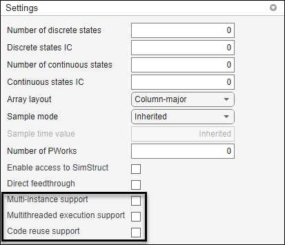
S-Function Builder with new flags, Multi-instance support, Multithreaded execution support, code reuse support

New SimStruct function ssIsModeUpdateTimeStep

Use the new SimStruct function ssIsModeUpdateTimeStep to determine when the simulation is in a time step where an update to the mode vector is allowed. Blocks that implement support for zero-crossing detection use a mode vector to change the mode of the output method.

In previous releases, S-function examples implemented blocks that support zero-crossing detection only for variable-step solvers and used the ssIsMajorTimeStep function to control when the mode vector updated. When you use the ssIsModeUpdateTimeStep function, the block can support zero-crossing detection for both variable-step and fixed-step solvers.

R2022a

New Features, Bug Fixes, Compatibility Considerations

Simulink Fundamentals course

You can now access the self-paced, interactive Simulink Fundamentals course that teaches you to:

  • Use the Simulink environment.

  • Model continuous and discrete dynamic systems.

  • Organize growing models in subsystems that create visual and functional hierarchy.

  • Componentize models by referencing other models and creating libraries.

  • Optimize simulation performance.

Simulink Fundamentals uses tasks to teach concepts incrementally, such as through a real-life example with a 3D printer. You receive automated assessments and feedback after submitting tasks. Your progress is saved when you exit the course, so you can complete the course in multiple sessions.
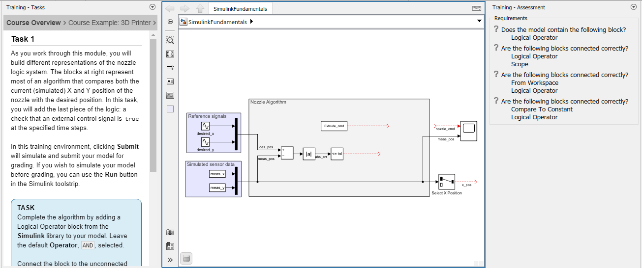
Simulink Fundamentals task

For more information, see Simulink Fundamentals.

Learn tab provides access to in-product trainings

The Simulink Start Page now has a Learn tab that provides access to in-product trainings, such as Simulink Onramp and Simulink Fundamentals.
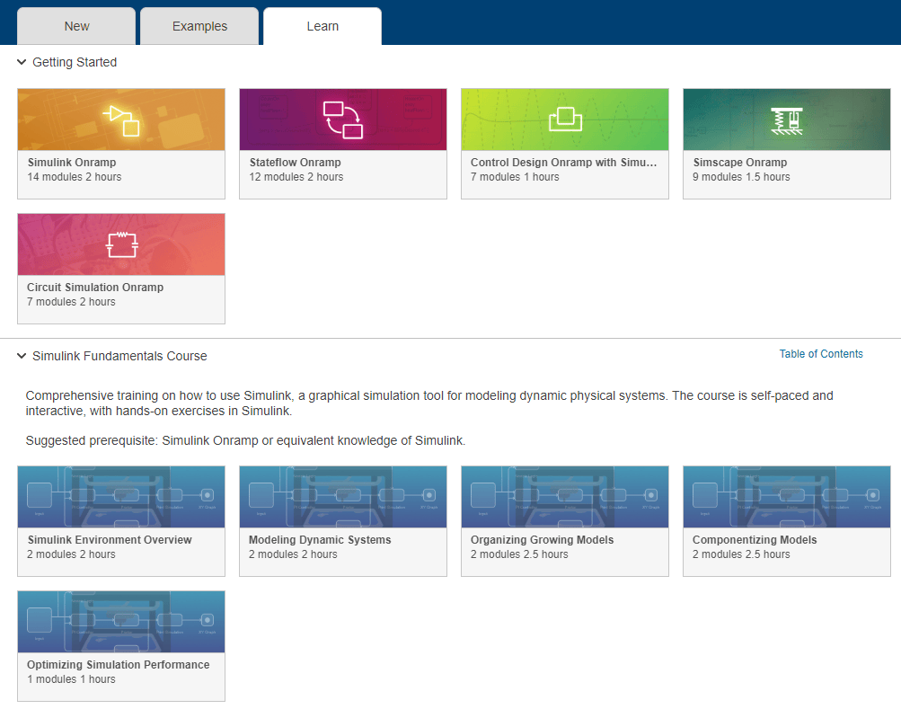
Learn tab of Simulink Start Page

Drop-down menu for Simulink Editor pane interactions

In Simulink Editor panes, a new button to the right of the pane title provides options to undock, minimize, and open help for the pane.

Next to the pane title, a drop-down button provides the option to undock the pane.

When a pane is not docked to the Simulink Editor, the button provides the option to dock and open help for the pane.

When a pane is minimized, the button provides the option to undock, restore, and open help for the pane.

 Compact Boundaries for Simscape Blocks Improve Model Layout and Readability

Simscape blocks that have unused space around the block icon and do not have a solid boundary line now get a more compact boundary in block diagrams. This enhancement affects only the block display and enables these improvements:

  • The signal lines pass near the new compact block boundary, which allows better autorouting of lines.

  • Icon, badge, annotation, and action bar for the block appears near the compact boundary of the block. The block background color applies only within the compact boundary, which improves readability.

  • Adjacent blocks align close to each other without overlap, which avoids truncation of content.

For example, see Resistor, Variable Resistor, and Capacitor blocks. The compact boundary improvements do not apply to blocks that have a solid boundary line, for example, PS Ramp and Gear Box blocks.
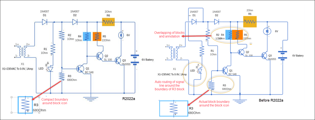
Compact boundary for Simscape blocks

 Compatibility Considerations

If you open a model created using a previous version of Simulink in R2022a and the model has compact blocks, then background color for such blocks is applied only within the compact boundary.

If you save a model created in R2022a to a previous version, the compact boundaries will be removed. Adjacent blocks can overlap, background color is applied to the complete block boundary, and signal lines can appear as passing through the block.

Highlight reduced nonvirtual blocks

You can now highlight nonvirtual blocks that are removed to reduce execution time during model simulation and code generation. To enable this functionality, select the model configuration parameter Block reduction. For more information, see Block reduction.
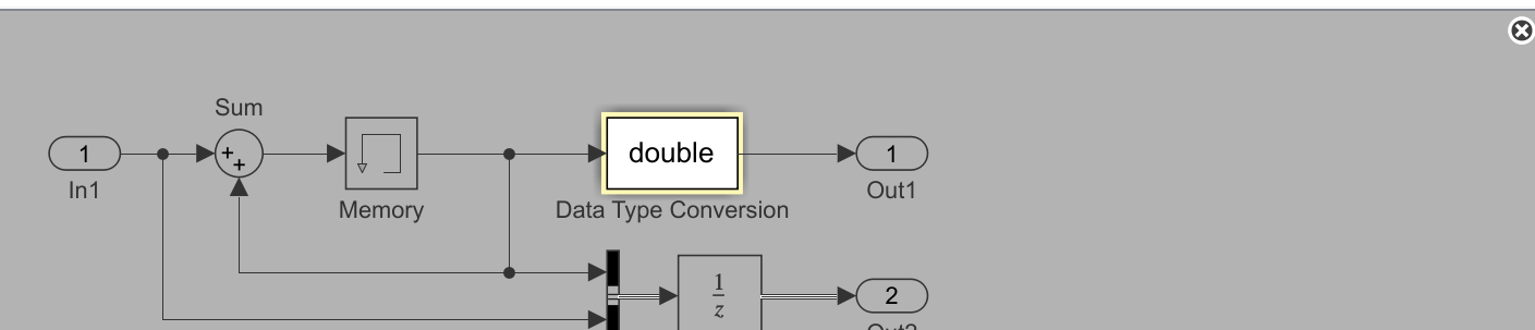
Simulink canvas with a simple model. Background is in grey, and one block, a Data Type Conversion block, is highlighted with a yellow border and white background. In the upper-right corner of the canvas, there is a circle containing an X.

Add State Reader, State Writer, and Parameter Writer blocks from Simulink toolstrip

You can now add State Reader, State Writer, and Parameter Writer blocks to your model directly from the Simulink toolstrip.

To add a State Reader or State Writer block, highlight by clicking on a block that has a state that the State Reader or State Writer block can read or write to. On the current block tab of the toolstrip, click Reader-Writer and select State Reader Block or State Writer Block from the list. A State Reader or State Writer block appears on the canvas with the State owner block parameter set to the block that was highlighted. The method of adding a State Reader or State Writer block by right-clicking and dragging a state owner block is no longer supported starting in R2022a.
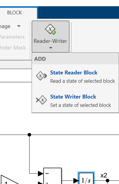
Excerpt from Block tab of Simulink Toolstrip showing button labeled "Reader-Writer", with dropdown menu showing "State Reader Block" and "State Writer Block" options. An Integrator block is highlighted on the canvas.

Note

Depending on the type of block you highlight, the current block tab of the toolstrip might be labeled with the name of the highlighted block, for example, Constant, or it might be labeled Block.

Similarly, to add a Parameter Writer block, highlight by clicking on a block with a parameter that the Parameter Writer block can write to. Then, on the current block tab of the toolstrip, click Parameter Writer. A Parameter Writer block appears on the canvas with the Parameter owner block parameter set to the block that was highlighted.
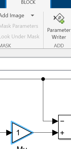
Excerpt from Block tab of Simulink Toolstrip showing button labeled "Parameter Writer". A Gain block is highlighted on the canvas

If you highlight a block that has both a state that the State Reader or State Writer block can read or write to and a parameter that the Parameter Writer block can write to, on the current block tab of the toolstrip, click Reader-Writer. Select Parameter Writer Block, State Reader Block, or State Writer Block from the list.
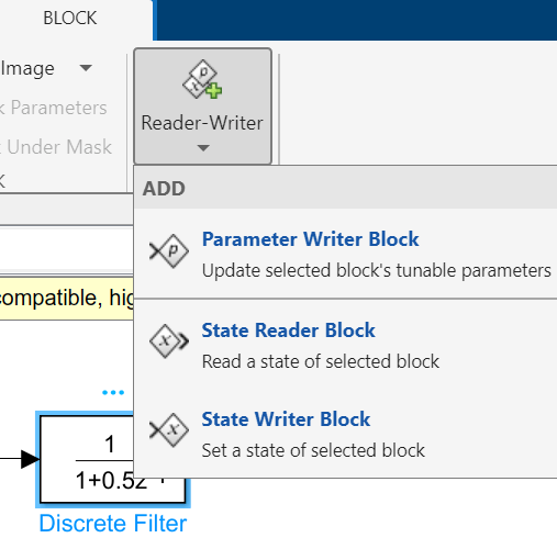
Excerpt from Block tab of Simulink Toolstrip showing button labeled "Reader-Writer", with dropdown menu showing "Parameter Writer Block", "State Reader Block", and "State Writer Block" options. A Discrete FIR Filter block is highlighted on the canvas.

After you add a State Reader, State Writer, or Parameter Writer block, cut and paste it to move it to the desired location within the model hierarchy.

Related block highlighting for Variant Connector and Parameter Writer blocks

Starting in R2022a, selecting a primary Variant Connector block, a Parameter Writer block, or a block related to either of them, highlights all blocks that are related to the selected block.

A primary Variant Connector block and all nonprimary Variant Connector blocks with the same Connector Tag as that primary block constitute a set of related blocks.
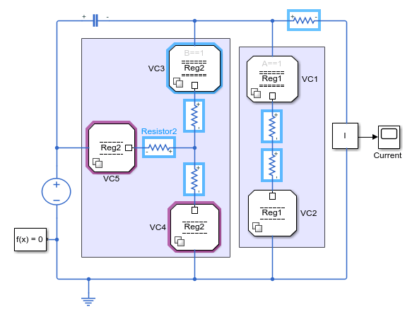
Model of an electric circuit, in which a primary Variant Connector block is selected, and its two related nonprimary Variant Connector blocks are highlighted

A Parameter Writer block and the parameter owner block of the value that it writes constitute a set of related blocks.
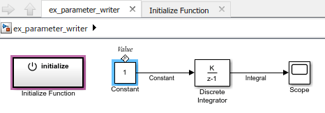
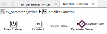
Model in which a Constant block is selected, and an Initialize Function block is highlighted

Contents of the Initialize Function block, containing a highlighted Parameter Writer block

When a related block is highlighted, blocks in the current model that contain the related block are also highlighted. For example, an Initialize Function block is highlighted when it contains a Parameter Writer block that is related to the selected block.

Port toolbar menu customizations to custom tab in toolstrip

A custom toolbar menu in the Simulink Editor can now be converted into a toolstrip tab using the slConvertCustomMenus command.

Converting a custom toolbar menu creates a toolstrip tab with a single section, which is populated by the converted menu items from the toolbar menu. List items from the menu are converted into push buttons, and list items with pop-up lists are converted into drop-down buttons.
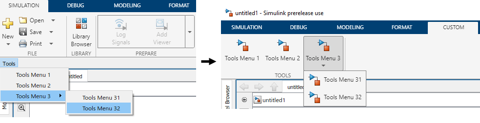
A custom toolbar menu on the left labeled Tools has two list items without pop-up lists and one list item with a pop-up list. The converted toolstrip tab is on the right and shows a single tab labeled TOOLS that has two push buttons and one drop-down button.

The toolbar menu is not automatically deleted during the conversion. You can remove it by commenting out or deleting the corresponding addCustomMenuFcn call in the sl_customization file.

Any functionality that custom tabs do not support is ignored during the conversion. However, you can edit the generated tab. For more information, see Create Custom Simulink Toolstrip Tabs.

View and trace callbacks

You can view and trace all the callbacks executed in a model. Enable the option Log Callbacks to record all callbacks executed in the model. To view the callback report, go to Diagnostics > Callback Tracer.

For more information, see View and Trace Callbacks in Model

Use modelfinder to find Simulink models

Using modelfinderyou can:

  • Find models that match the specified string in model name, blocks, annotations, or description.

    You can also find models that matches a specific search string and contains specified blocks. For example, you can search models that matches the search string dc motor in it and contains pulse generator and pi controller blocks.

  • Index models in a specific path. Register or unregister a folder to include all the models in that folder so that they appear in the modelfinder search results.

For more information, see modelfinder|modelfinder.registerFolder | modelfinder.unregisterFolder

Unified breakpoint list in the Simulink Editor for debugging

In R2022a, you can use the new breakpoint list in the Simulink Editor to manage breakpoints set in a model. The unified breakpoint list includes useful metadata and tools for navigating to, modifying, organizing, sorting, and searching the breakpoints in the list. The breakpoint list includes different types of breakpoints that you can set, for example, Stateflow and MATLAB Function blocks.

 Toolstrip-based UI for Model Advisor​​​​

The Model Advisor user interface now includes simplified toolstrip with new features.

  • Filter Checks - Filters the checks based on their respective result statuses, such as Failed, Passed, Justified.

  • Justify - Justify the violations. Justifications allow you to add a rationale for violations observed during Model Advisor analysis. For more information, see Justify Violated Blocks from the Model Advisor Check Analysis (Simulink Check).

  • Fix - Fixes the violations by setting the violated parameter values to recommended values.

  • Reports - Export Model Advisor analysis reports in HTML, PDF, and DOCX formats.

  • Manage Configurations - Create, load, restore, and associate configurations in simple workflows.

This table describes the changes to the menu items in the Model Advisor:

Previous UI ElementNew UI ElementDescription of the Change
Run Selected ChecksRun ChecksNo change in functionality. Use this button to run selected checks.
Settings > (options)Open > (options)Some older options are no longer available. Use this button to open or customize Model Advisor Configuration Editor.
Generate Report…Report > (options)No change in functionality. Use this button to generate the Model Advisor analysis report in HTML format. Use the drop-down option to selectPDF or WORD.
Configure Hidden input parametersConfigure input parameters in Model Advisor Configuration EditorConfigure hidden input parameters was a hyperlink in the check window. In R2022a, you can now click the Configure input parameters in Model Advisor Configuration Editor icon ().
Edit > Send Check IDs to WorkspaceRight-click on any check, and select Send Check IDs to Workspace.Use this option to send check IDs to workspace.
Edit > Send Instance IDs to WorkspaceRight-click on any check, and select Send Instance IDs to Workspace.Use this option to send instance IDs to workspace.

This table describes the navigation options removed from Model Advisor:

Navigation Options Removed
Settings > Treat as referenced model
Settings > Preferences
Edit > Reset
Switch to Model Advisor Dashboard
Run Checks in Background
Highlighting check results
Highlight exclusion results
Highlighting

For more information, see Run Model Advisor Checks and Review Results (Simulink Check).

 Functionality being removed or changed

Toolbar menu customization will be removed

Still runs

Toolbar menu customization will be removed in a future release. Use custom toolstrip tabs instead.

Custom tabs better integrate into the Simulink Toolstrip. Menu items that were previously hidden within the toolbar menus are directly available on custom tabs. For information on custom tabs, see Create Custom Simulink Toolstrip Tabs.

To migrate your toolbar menu customization, see Port toolbar menu customizations to custom tab in toolstrip.

New simulation status during initialization of fast restart simulation

Behavior change

Starting in R2022a, fast restart simulations clearly indicate when the simulation is restarting. While fast restart is in progress, the simulation status becomes Restarting, and the Simulink Editor becomes frozen like it is during model compilation and initialization.

In previous releases, the Simulink Editor and simulation status did not give an indication that fast restart was in progress. The table summarizes updates to messages in the Simulink Editor and to the SimulationStatus model configuration parameter value.

Simulation Status Information while Fast Restart is in ProgressBefore R2022aStarting in R2022a

Simulation status message in the bottom left of the Simulink Editor

Fast Restart (Ready)

Restarting

Model status in the bottom right of the Simulink Editor before simulation starts

Initialized

Compiled

SimulationStatus configuration parameter value

compiled

restarting

Models or scripts that conditionalize behavior based on the value of the SimulationStatus parameter might behave differently or give an error during fast restart simulations.

Unconnected block input ports, block output ports, and lines do not warn by default

Behavior change

Starting in R2022a, new models do not warn by default for unconnected block input ports, block output ports, or lines.

To enable the warnings, change the related configuration parameter values. On the Modeling tab, click Model Settings. In the Configuration Parameters dialog box, open the Diagnostics > Connectivity pane.

Simulation Analysis and Performance

Local solver

Starting in R2022a, you can speed up simulation in model references by using the local solver to choose different tradeoffs for different sections of a model, depending on your needs. This new feature lets you choose less expensive solvers for slower models.

Zero-Crossing detection using Fixed-Step Solver

Starting in R2022a, you can use fixed-step solvers to detect zero-crossings and locate events based on continuous zero-crossing signals that register events.

Change visualization for a subplot more easily in the Simulation Data Inspector

Starting in R2022a, the subplot menu and the context menu for subplots in the Simulation Data Inspector include an option to change the visualization for that subplot. Previously, to change the visualization for a subplot, you could only use the Visualization Gallery in the Simulation Data Inspector.
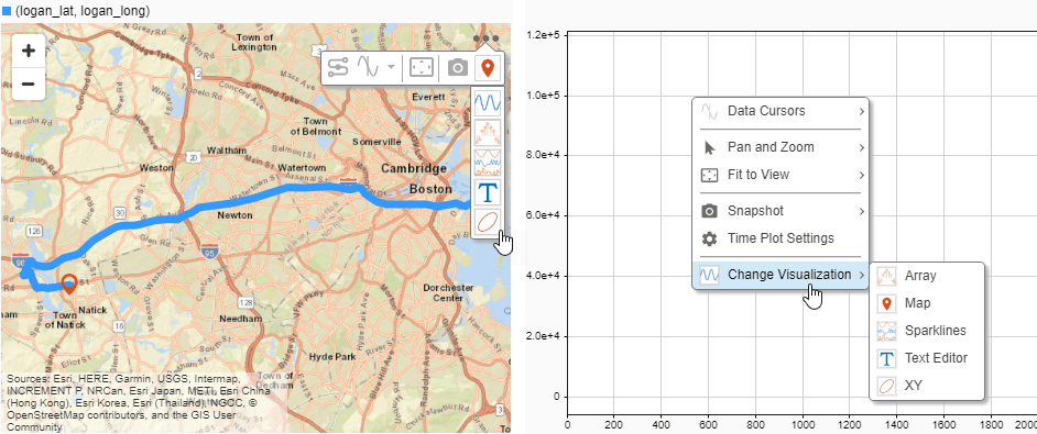
Map with the subplot menu open and the Change Visualization option expanded next to a time plot with the context menu open and the Change Visualization option expanded.

Changing the visualization for several subplots in the Simulation Data Inspector is also easier. The Visualization Gallery now remains open until you close it, and you can freely position the window within the plot area.

XY, sparklines, and map visualization enhancements

Several visualizations you can use in the Record block and Simulation Data Inspector have enhancements in R2022a:

  • When you add a trend line to an XY plot, the trend line now has a tooltip that shows:

    • The series and signals to which the trend line was fitted.

    • The x- and y-coordinates for the point nearest the pointer.

    • The trend line equation and R-squared value.

      Polynomial data plotted on an XY plot in the Simulation Data Inspector with the trend line tooltip visible.

  • The legend for the XY plot has a tooltip that indicates which run contains the plotted signal data.
    Legend for an XY plot in the Simulation Data Inspector with the legend tooltip visible.

  • Sparklines plots now show tick labels for the time axis only on the last sparkline with a visible time axis. You can control whether tick labels are shown for all sparklines or only the last sparkline using the Visualization Settings.
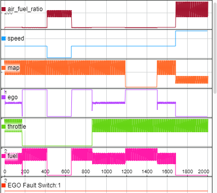
    Sparklines plot that displays data from several signals. Time axis labels are shown only on the last sparkline with a visible time axis.

  • Maps now show a legend that indicates which signals provide the latitude and longitude data for the plotted route. The legend has a tooltip that indicates which run contains the plotted data.
    Legend for a map in the Simulation Data Inspector with the legend tooltip visible.

Interactive comparison report enhancements

Interactive comparison reports created using the Simulation Data Inspector have these enhancements:

  • You can sort comparison results in the report by name, absolute tolerance, relative tolerance, maximum difference, and result.

  • The generated comparison report reflects the grouping in the Simulation Data Inspector at the time the report was generated. For example, when you group the results by data hierarchy, the results are grouped by data hierarchy in the generated report.

External debugger integration for debugging custom C/C++ code​

You can now debug your custom C/C++ code from within Simulink by launching an external debugger and setting breakpoints in your custom code. The following debuggers are supported:

  • On Windows, Microsoft Visual Studio® debugger

  • On Linux, GNU® Data Display Debugger (DDD)

  • On macOS, LLDB Debugger (LLDB)

To launch the external debugger, on the Debug tab of the Simulink toolstrip, in the Breakpoints section, click the arrow to the right of the Add Breakpoint button. From the menu, select Set Breakpoints in Custom Code.
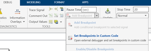
Excerpt from Debug tab of Simulink Toolstrip. The 'Add Breakpoint' dropdown menu is open, and 'Set Breakpoints in Custom Code' is the second option on the menu.

For more information, see Debug Custom C/C++ Code.

Parameter Combinations in Multiple Simulations panel

In R2022a, you can use Parameter Combinations in the Multiple Simulations panel of the Simulink Editor for workflows with multiple simulations, such as Monte-Carlo simulations and parameter sweeps. Parameter Combinations allows you to create sequential and exhaustive combinations of parameters, specify value ranges, and run simulations with these combinations

 Functionality being removed or changed

Simulink.sdi.setRunOverwrite function has been removed

Errors

In R2022a, the Simulink.sdi.setRunOverwrite function has been removed. Using the function in a script causes an error.

In R2018b, the Simulink.sdi.setRunOverwrite function was replaced. Since R2018b, the Simulink.sdi.setRunOvewrite function has had no effect on the Simulation Data Inspector, and scripts that use the function have generated a warning.

To retain data for only a single run in the Simulation Data Inspector, use the Simulink.sdi.setAutoArchiveMode function and the Simulink.sdi.setArchiveRunLimit function. Configure the Simulation Data Inspector to automatically move runs into the archive, and set the archive run limit to 0.

Simulink.sdi.setAutoArchiveMode(true);
Simulink.sdi.setArchiveRunLimit(0);

For more information about configuring the Simulation Data Inspector archive, see Archive Behavior and Run Limit.

Component-Based Modeling

Mask Editor streamlines masking workflow for Parameter Constraint, Port Constraint, and Parameter Promotion

In R2022a, the Mask Editor has new capabilities that enable you to perform masking operations with fewer clicks.mask editor 2.0
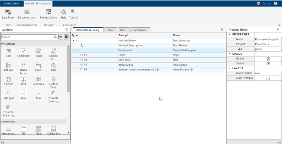
This table lists the new and improved capabilities in Mask Editor.

New and Improved Mask Editor Features

FeatureImproved or New?
Context-based tool strip for easy navigation – The menu options appear based on context. For example, the options for Parameter Constraint, Cross Parameter Constraint, and Port Constraint appear only when you select the Constraint tab.New
Integrated view of initialization code and callback code – You can view the mask initialization code and callback code in a single integrated MATLAB Editor. Previously, the initialization code and callback code were in different locations. The Mask Editor code functionalities are like those in the MATLAB Editor, with some limitations. For example, the autocomplete functionality is supported, but you cannot set a breakpoint in your code.New
Upload image within Mask Editor – You can set an image for the masked block icon within the Mask Editor. New

Icon drawing commands – The skeleton for drawing commands appears when you click the commands.

icon drawing commands

New

New Constraint Manager with support for port constraints – Constraint Manager is integrated inside the Mask Editor.

constraint manager

New

Copy mask definitions from Simulink library blocks – Search for the desired block and click Copy Mask to import the mask definition from an existing block.

copy mask

New

Enhanced Property Editor for parameters – The new Property Editor allows you to set values for parameters such as Tree, LUT Widget, Tunable Popup, Custom Table, and Text Area. For example, you can use the Property Editor to specify the column properties of a custom table. Previously, you had to set values in text form using delimiters.

property editor

Improved

Enhanced Parameter Promotion workflow – You can now promote parameters in fewer steps. An integrated view allows you to see all promotable parameters of a block. You can select multiple parameters to promote in the case of many-to-one parameter promotion. For more information, see Promote Block Parameters on a Mask

parameter promotion

Improved

Specify port constraints on masked block

Starting in 2022a onward, you can specify constraints on the input and output ports of a masked block. The port attributes are checked against the constraints when you compile the model.

For more information, see Validate Input and Output Port Signals Using Port Constraints.

Bus Editor enhancements

The Bus Editor loads faster and has an updated interface for creating, modifying, and managing bus objects.

  • A toolstrip provides easy access to actions.

  • A Sources pane provides the available object sources.

  • An interactive table displays editable information about the objects, such as hierarchy and properties.

  • A Property Inspector pane lets you focus on one object at a time and edit its properties.
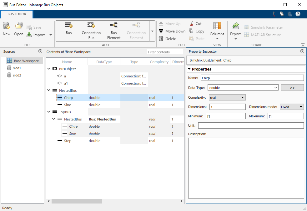
Updated Bus Editor appearance

For more information, see Bus Editor.

Message Triggered Subsystem and Message Polling Subsystem blocks: Process messages by executing subsystem when message is available

The new Message Triggered Subsystem and Message Polling Subsystem blocks are each a type of conditionally executed subsystem that uses messages as the control signal. The information contained in the messages is accessible inside the subsystem.

  • A Message Triggered Subsystem block executes whenever a message is available at the control port, independent of block sample time.

  • A Message Polling Subsystem block pulls messages from a queue periodically based on its sample time and executes only when a message is available.
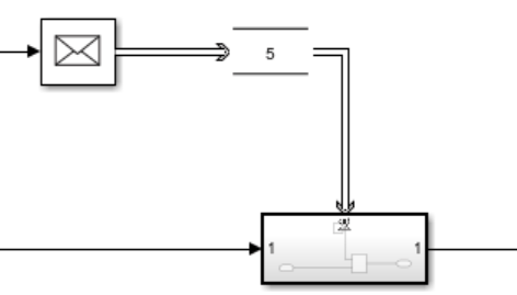
Simulink canvas with Message Send block connected to Queue block which is connected to control port of Triggered Subsystem block

A Message Triggered Subsystem block can be used to define an independent function at the root level of an export-function model. See Export-Function Models Overview.

For more information about the Message Triggered Subsystem and Message Polling Subsystem blocks, see Message Triggered Subsystem and Using Message Polling and Message Triggered Subsystems.

Reinitialize ports and Reinitialize Function block: Reinitialize referenced model or subsystem states during simulation

Starting in R2022a, you can reinitialize the states of the blocks inside a referenced model or subsystem at any time during model simulation. Sending a function-call signal to a reinitialize port of the Model block or the Subsystem block creates a reinitialize event that implicitly initializes the states of all blocks within the Model or Subsystem block.
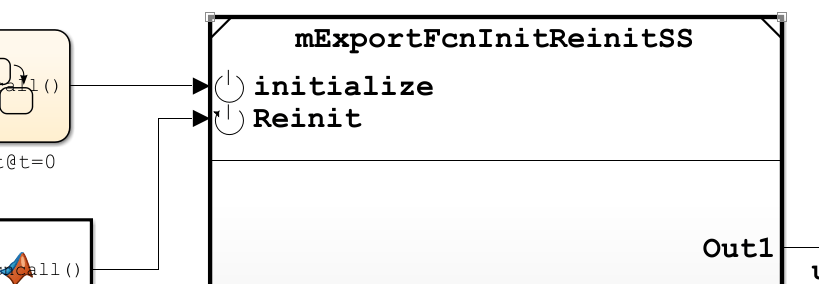
Simulink canvas with a Model block displaying an Initialize port driven by a Stateflow chart and a Reinitialize port driven by a MATLAB Function block

To add a reinitialize port to a referenced model or a subsystem, place a Reinitialize Function block inside the referenced model or subsystem. Then, select the Show model reinitialize ports check box in the Model block parameters dialog or the Show subsystem reinitialize ports check box in the Subsystem block parameters dialog. The Model or Subsystem block displays a reinitialize port, indicated by the Reinit icon icon.

By customizing the contents of a Reinitialize Function block, for instance by using State Writer and Parameter Writer blocks, you can configure a reinitialize event to explicitly override specified states in a referenced model or subsystem in addition to implicitly initializing all states in the referenced model or subsystem. See Reinitialize States of Blocks in Subsystem.

A reinitialize event can be used to initialize states of blocks inside nested subsystems or referenced models and to initialize certain types of blocks that are not affected by an Enabled Subsystem block reset.

You can place multiple Reinitialize Function blocks inside a referenced model or subsystem. In this case, Simulink creates a reinitialize port for each Reinitialize Function block, with each port name corresponding to the Event name of the reinitialize event as specified in the Event Listener block inside the Reinitialize Function block.

Function ports and port-scoped Simulink Function blocks: Call and define functions across peer models

Starting in R2022a, Simulink models can have function ports through which one referenced model calls a function defined in a second referenced model. A model can issue a function call through an invoking function port created by a Function Element Call block to invoke a function defined in another model using a port-scoped Simulink Function block and exported through an exporting function port created by a Function Element block. You can use function ports to model client and server components in a distributed service architecture as well as to facilitate data sharing using a functional interface between component models. See Call Simulink Functions in Other Models Using Function Ports.

Code reuse support in code generation

In previous releases, code generated from Simscape models did not support code reuse. This limitation has now been removed.

Use the new match filter with find_system to find both active and inactive blocks in a model

You can use the built-in match filter, Simulink.match.allVariants(), with the find_system function to find all blocks in a variant model regardless of whether the block is active or inactive due to variants.

For more information, see MatchFilter.

Find variant control variables used by variant parameters

Starting in R2022a, the import control variables operation in Variant Manager and the Simulink.VariantManager.findVariantControlVars method find variant control variables used by variant parameters (Simulink.VariantVariable) that are accessible to the model. See, findVariantControlVars.

Compile code conditionally for all variant parameter values with different dimensions

You can generate code for active and inactive values of variant parameters that have different dimensions. All other attributes, such as data type and complexity, must be the same across all choices of a variant parameter.

When you generate code for variant parameters with different dimensions, with the activation time of the associated variant control variable object to code compile, Embedded Coder generates code for active and inactive values of variant parameters. The code contains variant parameter definitions and an autogenerated dimension identifier in C preprocessor conditionals #if and #elif. The C preprocessor conditionals enable you to conditionally compile the code for a given active value of a variant parameter. You do not need to regenerate the code every time you change the value of the variant control variables that are associated with variant parameters. For more information on conditionally compiling code, see Compile Code Conditionally for all Values of Variant Parameters with Same and Different Dimensions.

Previously, if a variant parameter had values with different dimensions, you could generate code only for the active values. You had to regenerate the code every time you changed the value of the variant control variable before compiling the code.

Consider this model.
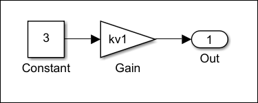
Variant parameters with choice values having different dimensions in a Simulink model

In this model, the Gain parameters of the Gain blocks are set to the variant parameter kv1.

  1. In the MATLAB Command Window, define kv1 as follows. kv1 has values with different dimensions, and the variant activation time of the associated variant control variable object V is set to code compile. Set the storage class of kv1 with exported data scope to generate a code that reuses the variant parameter values that you specified in the model. You can choose to generate a code that imports variant parameter values and its dimensions from external code prior to code compilation by setting the storage class with imported data scope. For more information, see described in Choose Storage Class for Controlling Data Representation in Generated Code (Embedded Coder). In this example, the storage class of the variant parameters is set to ExportedGlobal (Embedded Coder).

    % exported parameters
    spec = Simulink.Parameter();
    spec.CoderInfo.StorageClass = 'ExportedGlobal';
     
    % variant parameters
    choice1 = 'V == 1';
    choice2 = 'V == 2';
    choice3 = 'V == 3';
    kv1 = Simulink.VariantVariable('Choices', {choice1, [1, 2, 3, 4], choice2,
     [1, 2, 3, 4, 5], choice3, [1, 2, 3, 4, 5, 6]},'Specification', 'spec');
    
    % variant control variable
    V = Simulink.VariantControl('Value', 1, 'ActivationTime', 'code compile');

  2. Generate the code using Embedded Coder. The code that you generate contains the variant parameter definition section that has active and inactive values of kv1 that you specified in the model. The code also contains the dimension identifier kv1_dim0 to store the dimensions of variant parameter values across the model.

    //mVPrmVariableDim.c
    #if V == 1
    real_T kv1[kv1_dim0] = { 1.0, 2.0, 3.0, 4.0 };
    
    #elif V == 2
    real_T kv1[kv1_dim0] = { 1.0, 2.0, 3.0, 4.0, 5.0 };
    
    #elif V == 3
    real_T kv1[kv1_dim0] = { 1.0, 2.0, 3.0, 4.0, 5.0, 6.0 };
    #endif
    
    //rtw_variant_dims.h
    /* Definition for custom storage class: Define */
    #if V == 1
    #define kv1_dim0                       4                                                  
    #elif V == 2
    #define kv1_dim0                       5                                                  
    #elif V == 3
    #define kv1_dim0                       6                                                  
    #endif                             
    

    When you compile this code, the compiler evaluates the #if and #elif conditions to determine the active values and dimension of variant parameters based on the value of the variant control variable V that you provide as an input to the compiler. If you specify the value of V as 1, the condition V == 1 evaluates to true, and the values enclosed in V == 1 becomes active during code compilation. You can then specify a different value for V and recompile the same code for any other active value of kv1.

Reuse, control representation, and import variant parameter values in generated code using Simulink.Parameter variables

You can specify Simulink.Parameter variables as values in variant parameters. Using Simulink.Parameter variables allows you to share values among multiple variant parameters, separate values from their data types and other properties, and control the appearance, placement, definition, and declaration of variant parameters values in the generated code. Simulink.Parameter variables help you to import variant parameter values from external code at the beginning of code compile, simulation-loop, and model startup phases of simulation and code generation workflows based on the activation time you specify. For more information, see Stages to Set Active Choices in Variant Blocks and Variant Parameters. When you use Simulink.Parameter variables as values in a variant parameter, corresponding properties of all the Simulink.Parameter variables must be the same. Only the values of Simulink.Parameter variables can vary.

Previously, you could specify only numeric values in variant parameters.

Consider this model.
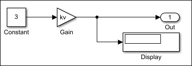
Simulink model with Simulink.Parameter objects as choice values in variant parameters

In this model, the Gain parameter of the Gain block is set to the variant parameter kv.

  1. In the MATLAB Command Window, define kv as follows. kv has the two values kv_hatchback and kv_sedan of Simulink.Parameter type, and the storage class is set to ImportedExtern.

    % imported parameters
    kv_hatchback = Simulink.Parameter(3);
    kv_sedan = Simulink.Parameter(6);
    kv_hatchback.CoderInfo.StorageClass = 'ImportedExtern';
    kv_sedan.CoderInfo.StorageClass = 'ImportedExtern';
    
    % variant parameters
    kv = Simulink.VariantVariable('Choices', {'V == 1', 'kv_hatchback',
     'V == 2', 'kv_sedan'});
    

  2. Define a variant control variable object V with the value set to 1 and the activation time set startup.

    V = Simulink.VariantControl('Value', 1, 'ActivationTime', 'startup');

  3. Generate the code using Embedded Coder or Simulink Coder. The code is generated as follows.

    //vPrmImported_private.h
    extern real_T kv_hatchback;                    
    extern real_T kv_sedan;
    
    //vPrmImported.c
    void vPrmImported_initialize(void) {
    if (V == 1) {
        mVPrmImported_P.kv = kv_hatchback;
      } else if (V == 2) {
        mVPrmImported_P.kv = kv_sedan;
      }
    }
    

    The initialize function of the generated code is executed at the model startup phase to determine the active value of kv based on the variant condition that evaluates to true. If the condition V == 1 evaluates to true, kv_hatchback is active. If V == 2 evaluates to true, kv_sedan is active. The generated code imports active values from external code at model startup.

For more information, see Reuse Variant Parameter Values from Handwritten Code Using Simulink.Parameter Variables.

Use enumerated values to improve code readability of variant blocks and variant parameters with startup activation time

You can associate enumerated type of values for the variant control variables with startup activation time. Enumerated types improve code readability and simplify the generated code by giving descriptive names to integers used as variant control values in variant control variable objects. For more information, see Enumerated Types To Improve Code Readability of Variant Control Variables of Variant Blocks and Improve Code Readability of Variant Parameters Using Enumerated Types.

Only enumerations that defined using these techniques are supported:

  • Using the function Simulink.defineIntEnumType

  • By subclassing one of these built-in classes:

    • Built-in integer data types int8, int16, int32, uint8, or uint16

    • Simulink.IntEnumType

These enumerations are also supported when permanently stored in a Simulink data dictionary. See Enumerations in Data Dictionary.

Mask parameter enhancements

Starting in R2022a, you can specify the Image and Value Type for the Data Type parameter. You can also have an embedded browser in the mask dialog by specifying HTML Text as Text Type for the Text Area parameter.

Retrieve list of options and evaluated value of a parameter

Starting R2022a, you can retrieve the list of options for a parameter, Simulink object, block diagram, and annotations using the get_param keyword options. You can also access the evaluated value of a masked parameter using get_param with the keyword value.

Use this syntax to get the list of options:

get_param(<block_path>,’options@<parameter_name>’);

Use this syntax to get the evaluated value is:

get_param(<block_path>,’value@<parameter_name>’);

Here, block_path is the block, parameter_name is the name of the parameter on the block whose list of options or evaluated value is to be retrieved.

For more information, see get_param

Constraint Manager integrated with Mask Editor

The Constraint Manager is now integrated inside the Mask Editor. The workflow for sharing constraints is simplified, and you can specify constraints for the input and output ports of blocks.

  • In the current shared constraint workflow, the Constraint Manager is opened in a separate window, and you must create a constraint, save it in a MAT file, and associate the file name with the parameter. Now, you can create or load a MAT file, define constraints or modify existing ones, and associate constraints with parameters within the Mask Editor. The Constraint Browser allows you to manage shared constraints.
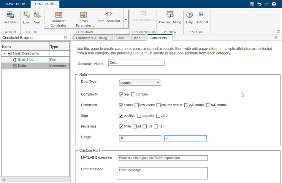
    constraint manager

  • You can use port constraints to specify constraints on the input and output ports of a masked block. The port attributes are checked against the constraints when you compile the model.port constraint

Control Subsystem Reference programmatically

Variable-size signals in array of buses

Starting in R2022a, signals of a bus type containing variable-size signals can form an array of buses, and an array of buses can be a variable-size signal. See Variable-Size Signal Basics and Group Nonvirtual Buses in Arrays of Buses. Support for such signals is limited to normal mode simulation, and not all blocks are supported.

 Designation of export-function model

Starting in R2022a, Simulink allows you to explicitly designate a model as an export-function model. See Export-Function Models Overview. Previously, Simulink attempted to determine whether or not a model was an export-function model by analyzing the contents of the model.

After you designate a model as an export-function model, Simulink performs compile-time checks to warn you if the model does not meet export-function model requirements.

Simulink displays a Badge showing "f()" badge in the lower-left corner of the canvas to indicate that a model is designated as an export-function model.

If you load a model that was created and saved in a prior release, Simulink designates the model as an export-function model if the model meets the requirements to be an export-function model. In some cases, you may need to manually designate such a model as an export-function model.

For more information, see Designating an Export-Function Model.

Redesigned Simulation Target Pane of Model Configuration Parameters

The Simulation Target pane of the Model Configuration Parameters dialog is changed for R2022a. The parameters that pertain to custom code are now together in one section of the dialog, which is organized into three tabs: Code information, Additional source code, and Import settings. Clicking on a tab shows the parameters that are listed under that tab and hides the contents of the other two tabs.

Some of the parameters have new names, and two parameters, Compiler flags and Linker flags, both found on the Code information tab, are new for R2022a.

In the Compiler flags field, you can enter any additional compiler flags to be added to the compiler command line when your custom code is compiled.

In the Linker flags field, you can enter any additional linker flags to be added to the linker command line when your custom code is linked.
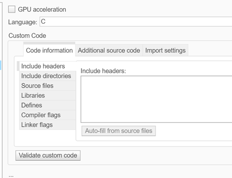
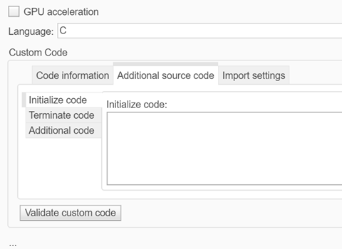
Code information tab of Simulation Target pane of Model Configuration Parameters dialog

Additional source code tab of Simulation Target pane of Model Configuration Parameters dialog

Import settings tab of Simulation Target pane of Model Configuration Parameters dialog

The following table lists the parameters in the new Simulation Target pane dialog that have different names or are in different locations as a result of this change.

Parameter name prior to R2022aNew name in R2022aNew location in R2022a
Insert custom C code in generated > Header fileInclude headersCode information tab
Insert custom C code in generated > Source fileAdditional codeAdditional source code tab
Insert custom C code in generated > Initialize functionInitialize codeAdditional source code tab
Insert custom C code in generated > Terminate functionTerminate codeAdditional source code
Additional build information > Source filesSource filesCode information tab
Additional build information > Include directoriesInclude directoriesCode information tab
Additional build information > LibrariesLibrariesCode information tab
Additional build information > DefinesDefinesCode information tab
Import custom code Advanced parameters
Simulate custom code in a separate process Import settings tab
Enable custom code analysis Import settings tab
Enable global variables as function interfaces Import settings tab
Undefined function handling Import settings tab
Deterministic functions and Specify by function Import settings tab
Default function array layout and Exception by function Import settings tab
Reserved names Advanced parameters

Interactively update legacy code in a System object

Starting in R2022a, you can interactively update legacy code in a System object.

In the MATLAB Toolstrip, the Inspect button replaces the Analyze button for System objects. The Analyzer that opens when you click the Inspect button now provides warnings for legacy base classes, properties with legacy attributes, and redundant methods. When a System object contains legacy code, the Analyzer displays an Update button that replaces or removes the legacy code.

For more information, see Analyze System Object Code.

Half-precision data type support for System objects

Starting in R2022a, MATLAB System objects support the half-precision data type for input, output, and System object property values. The half-precision data type is not currently supported for simulation or code generation in the MATLAB System block.

MATLAB class object is now a non-tunable Parameter

Starting in R2022a, MATLAB class objects are a non-tunable parameter in the MATLAB System block. This property can be set in the block dialog and is no longer read-only.

String support for messages in MATLAB System block

In R2022a, the MATLAB System block supports messages whose payloads contain strings. Message payloads containing strings are only supported in interpreted mode.

Enhancements to co-simulation numerical compensation user interface

In R2022a, the numerical compensation user interface has these enhancements:

  • Right-click access in the menu of the co-simulated component under Configure Cosimulation Signal Compensation

  • Settings for Auto, Always, or Off

  • New user interface to see options and conditions for each port

Numerical Compensation User Interface
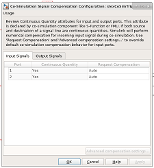
Numerical compensation dialog box

For more information, see Numerical Compensation.

In previous releases, these settings were in separate interfaces and you could only programmatically set the numerical compensation.

Multi-instance Simulink Function blocks

In R2021b, Simulink generated an error when you simulated a Stateflow Chart or MATLAB Function block that called a multi-instance Simulink Function block.

In R2022a, you can simulate a Stateflow Chart or MATLAB Function block that calls a multi-instance Simulink Function block. To specify a multi-instance Simulink Function block, configure the referenced model that includes the Simulink Function block. In the referenced model, set the model configuration parameter Total number of instances allowed per top model to Multiple.

New example of parsing NMEA GPS Text Messages Using Simulink and Python.

A new example shows how to parse text messages in NMEA GPS format using Simulink and Python. For more information, see Integrate Python GPS Text Message Parsing Algorithms in Simulink.

New example of modeling a distributed wireless tire pressure monitoring system

A new example shows how to design, model, and simulate a distributed monitoring system. In the example, multiple sensors communicate wirelessly with a controller. The controller takes action when it detects a fault condition and maintains a log of fault conditions. The example also shows how to prepare this model to generate code that is deployable on a target hardware platform where the model algorithm is implemented as a component as part of a system.

For more information, see Wireless Tire Pressure Monitoring System with Fault Logging and Prepare Sensor and Controller Models in a Distributed Monitoring System for Code Generation.

 Functionality being removed or changed

SortedOrder parameter no longer supported

Behavior change

Starting in R2019b, the SortedOrder parameter is no longer supported, and its value is ignored.

Bus Editor no longer supports custom import and export functions

Errors

The Bus Editor no longer supports custom import and export functions.

Remove the cm.BusEditorCustomizer.importCallbackFcn and cm.BusEditorCustomizer.exportCallbackFcn registration functions from the sl_customization function. To eliminate both customizations in one operation for a customization manager object named cm, enter:

cm.BusEditorCustomizer.clear
For more information about customizations, see Register Customizations with Simulink.

Project and File Management

Projects: Reduce test runtime in continuous integration workflows using the dependency cache

You can now specify where your project stores the dependency analysis results. In agile development workflows that use Git and a continuous integration (CI) server, share the dependency cache file (.graphml) to run an incremental dependency analysis and reduce the test suite runtime. See Continuous Integration Using MATLAB Projects and Jenkins.

To set the project dependency cache file, on the Project tab, in the Environment section, click Details. In Dependency cache file, browse to and specify a GraphML file. If the cache file does not exist, the project creates it for you.

Alternatively, you can create and set the project dependency cache programmatically:

matlab.project.example.timesTable
proj = currentProject;
proj.DependencyCacheFile = "myProjectCacheFile"

Project API: Export top-level and referenced project to previous version using Simulink.exportToVersion

You can now use Simulink.exportToVersion to export the top-level project with all references to open in a previous version of Simulink.

Dependency Analyzer: Save dependency graph as image

You can now save the dependency analysis results as an image. See Export Dependency Analysis Results.

Projects Examples: Determine optimal order for resolving conflicts

When collaborating on a project, a branch merge can lead to several conflicted files. Use the Dependency Analyzer to programmatically determine the optimal order in which to resolve conflicts. See Determine Order for Resolving Conflicts Using Dependency Analyzer.

Text Comparison: Save results as HTML report

You can now use the Comparison Tool to publish text comparison results in an HTML report. For more details, see Compare Text Files.

Folder Comparison: Compare folders in MATLAB Online

Starting in R2022a, you can compare folders and zip files in MATLAB Online.

You can access the comparison tool from:

  • The MATLAB Current Folder browser context menu

  • The Current Project browser context menu

  • The MATLAB Command Window using the visdiff function

 Functionality being removed or changed

Simulink will no longer support getting parameters of the default block diagram

Warns

Getting parameters of the default block diagram will not be supported in a future release. In R2022a, scripts that use get_param(0,parameter) continue to work but throw a warning.

Data Management

Import Simulink Design Verifier sldvData data into Signal Editor user interface

To edit data in MAT-files that contain Simulink Design Verifier sldvData structures, use the Simulink.io.SLDVMatFile class to create a custom reader that imports sldvData data into the Signal Editor user interface.

Signal Editor user interface tabular improvements

The Signal Editor user interface has these tabular improvements:

  • You can now navigate through the Signal Editor user interface tabular area using Tab and Shift+Tab. For more information, see Work with Basic Signal Data with a Tabular Editor.

  • To access a context menu of tabular area edits, right-click in the tabular area. You can:

    • Edit a row.

    • Insert or delete a row.

    • Replace the contents of a row with a MATLAB expression.

Root Import Mapper updates

  • When you are ready to map your data to input ports, the Root Inport Mapper now has a context menu that contains the same mapping options as the Map to Model button.

  • The Map to Model options are now enabled by context. In previous releases, all options were enabled and an error message was returned if you selected an unavailable option.

Relax data consistency checking across model hierarchies

Previously, Simulink enforced data consistency across data sources in a model reference hierarchy. Duplicate data definitions could only exist in a hierarchy under these conditions:

  • Each model in the hierarchy can see only one definition.

  • Definitions must be the same across models in the hierarchy.

In R2022a, the model parameter EnforceDataConsistency provides the option to relax the second condition, which allows you to more easily integrate Simulink models for large-scale simulations. When you use the set_param function to set EnforceDataConsistency to off, the current model and the models below it in the model hierarchy can use symbols with the same name but different values as long as each model in the hierarchy can see only one definition of the symbol.

set_param(bdroot,'EnforceDataConsistency','off');

By default, Simulink enforces data consistency, so the parameter is set to on. You cannot set EnforceDataConsistency to on for a model unless each of its referenced models and their variants also set EnforceDataConsistency to on.

Disable consistency checking only when simulating a model in Normal mode. Setting EnforceDataConsistency to off results in error for:

  • Code generation

  • SIL and PIL simulations

  • Simulation of a model hierarchy that contains one or more models running in Accelerator or Rapid Accelerator mode

  • Simulation of a protected model

For more information, see Considerations before Migrating to Data Dictionary.

Model argument enhancements for Simulink.LookupTable and Simulink.Breakpoint objects

In R2022a, these changes enhance the usability of Simulink.LookupTable objects configured as model arguments.

  • When you configure a Simulink.LookupTable object as a model argument, you can now also configure a Simulink.Breakpoint object that is referenced by that Simulink.LookupTable as a model argument. Configure a Simulink.Breakpoint object as a model argument by selecting the Argument check box in the Model Explorer, Simulink.Breakpoint property dialog box, Model Data Editor, or Property Inspector.

    A Simulink.Breakpoint object that is configured as a model argument can be used in a Simulink.LookupTable object when the Breakpoints specification property is set to Reference. When using a Prelookup block with an Interpolation Using Prelookup block in your model, this combination of a Simulink.LookupTable object with a Simulink.Breakpoint object allows you to share a breakpoint object between multiple Prelookup blocks and provide breakpoint values for each model instance.

    When you configure a Simulink.Breakpoint object as a model argument, a parent model can provide the instance-specific value for the model argument by:

    • Using a Simulink.Breakpoint object.

    • Providing an array of numeric values that define the breakpoints. The array must match the design definition for the breakpoint object. Simulink synthesizes a Simulink.Breakpoint object by using the values in the array.

  • When a parent model provides a Simulink.LookupTable object as an instance-specific value for a model argument, Simulink passes only the Table property of the lookup table object to the child model. This action applies to Simulink.LookupTable objects with Specification set to Reference. This behavior change allows you to configure model arguments for Simulink.LookupTable objects and Simulink.Breakpoint objects independently of each other and reuse these objects as instance parameters for multiple Model blocks.

For more information, see Parameterize Instances of a Reusable Referenced Model.

Block Enhancements

C Function block can interface with C++ classes

Starting in R2022a, code that you specify in the C Function block can interface directly with C++ classes defined in your custom code. You can:

  • Instantiate an object of a C++ class defined in your custom code

  • Read and write to public data members of the class object

  • Call public class methods of the object

Previously, it was necessary to write and call C wrapper functions to access C++ classes from the C Function block.

For more information, see Interface with C++ Classes Using C Function Block.

Enhanced Lookup Table Editor

The Lookup Table Editor has a new look and feel.
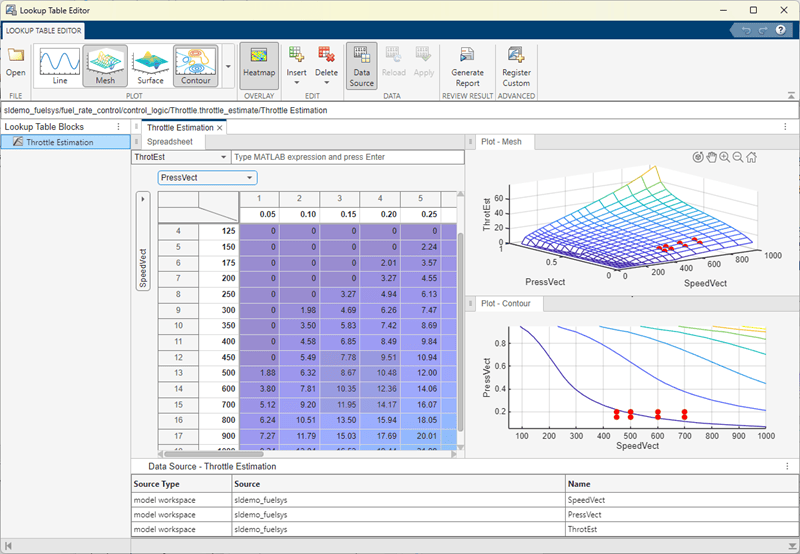
Lookup Table Editor for Throttle Estimation lookup table block in sldemo_fuelsys

This graphic is a view of the Lookup Table Editor for the Throttle Estimation lookup table block in the sldemo_fuelsys model.

Highlights of the new interface include:

  • Multiple ways to access the Lookup Table Editor, including from the Simulink Editor toolstrip, MATLAB command line, and lookup table block dialogs.

  • From within the Lookup Table Editor, the ability to view lookup tables from models loaded in the current MATLAB session.

  • Visualization and editing of lookup table data in a consistent way similar to Microsoft Excel, regardless of the data source.

  • A navigation field that lets you enter the path to models and subsystems that contain lookup table blocks, and lookup table blocks themselves.

  • Report generation containing lookup table data and surface plots.

    • For 1-D data, the report generates line plots.

    • For more than 1-D data, the report generates surface plots, one plot for each 2-D slice of data.

  • In the tabular area, the Lookup Table Editor contains the same lookup table spreadsheet as is available through the Simulink.LookupTable property dialog box (Edit Lookup Table Data with Lookup Table Spreadsheet).

  • Easy registration of custom lookup table blocks.

  • Generation of different plots for the data, including line, plot, surface, and contour plots.

  • Heatmap views for data.

For more information, see Use the Lookup Table Editor.

Lookup Table blocks updated for better sharing and reuse

These blocks have been updated to better share and reuse utility functions in generated code:

  • n-D Lookup Table

  • 1-D Lookup Table

  • 2-D Lookup Table

  • Interpolation Using Prelookup

Configure Dashboard Scope plots more easily using subplot menu

You can now use the new subplot menu for the Dashboard Scope to:

  • Show or hide data cursors.

  • Zoom out by a fixed amount.

  • Configure the mouse interaction to pan and select or to zoom in time, in y, or in both time and y.

  • Perform a fit-to-view in time, in y, or in both time and y.

To open the subplot menu on the Dashboard Scope block, select the block then click the three dots that appear when you pause on the plot area.
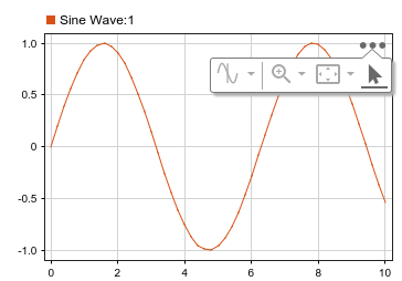
A selected Dashboard Scope block with the subplot menu visible.

In previous releases, you accessed these options using the context menu for the Dashboard Scope block.

New Matrix Operations blocks

The Matrix Operations library has these new blocks:

New Logic and Bit Operations library blocks

The Bit to Integer Converter and Integer to Bit Converter blocks have been added to the Simulink > Logic and Bit Operations library and remain available in the Communications Toolbox > Utility Blocks library. All existing models continue to work.

Trigonometric Function block updates

The Trigonometric Function block now lets you:

  • Change the lookup table algorithm table data types. When you select Lookup for the Approximation method parameter, use the Data Types tab. In previous releases, the table data type was derived from the input data type.

  • Control how the lookup table algorithm interpolates the table value using neighboring breakpoints. Use the new Interpolation method parameter and select Linear point-slope or Flat. In previous releases, Linear point-slope was the only interpolation method.

New Message Triggered Subsystem and Message Polling Subsystem blocks

The Message Triggered Subsystem and Message Polling Subsystem blocks are added to the Messages & Events library for R2022a. Use these blocks to create a subsystem whose execution is controlled by message input. See Message Triggered Subsystem and Using Message Polling and Message Triggered Subsystems.

New Reinitialize Function block and reinitialize ports for Model and Subsystem blocks

The Reinitialize Function block is added to the User-Defined Functions library for R2022a. Use this block to create a subsystem that executes upon a model or subsystem reinitialize event. The block contains an Event Listener block with the Event type set to Reinitialize.

The Model block has a new parameter, Show model reinitialize ports, and the Subsystem block has a new parameter, Show subsystem reinitialize ports. In both cases, when the parameter is selected, the block displays a port or ports that can be used to generate a model or subsystem reinitialize event.

Port-scoped Simulink Function blocks

A new port-scoped visibility option for the Simulink Function block is added for R2022a. To create a port-scoped Simulink Function block, set the Function visibility parameter of the Trigger block inside the Simulink Function block to port and enter the port name in the Scope to port field. Use port-scoped Simulink Function blocks to implement functions called through exporting function ports created by Function Element blocks. See Call Simulink Functions in Other Models Using Function Ports.

New Function Element and Function Element Call blocks

The Function Element and Function Element Call blocks are added to the Ports & Subsystems library for R2022a. Use these blocks to create exporting function ports and invoking function ports, respectively, in referenced models. See Call Simulink Functions in Other Models Using Function Ports.

New capabilities for Parameter Writer block

Starting in R2022a, the Parameter Writer block can write to the following:

  • Parameters of other blocks that are tunable during simulation

  • Instance parameters belonging to a Model block referencing a model

  • Masked subsystem parameters

  • Model workspace variables

Previously, the Parameter Writer block could write only to instance parameters belonging to a Model block referencing a model.

Additionally, starting in R2022a, the Parameter Writer block can be used inside all conditionally executed subsystems, as well as inside Initialize Function, Reinitialize Function, and Reset Function blocks. Previously, the block could be used only inside Initialize Function and Reset Function blocks.

For more information, see Initialize and Reset Parameter Values.

C Function block can access custom code global ND arrays

Starting in R2022a, the C Function block can access global variables defined in your custom code that are multidimensional arrays or struct types with multidimensional array fields.

C Caller and C Function blocks support 64-bit integer types as int64 and uint64

Starting in R2022a, you can import custom C code with 64-bit integer types and use such code with C Caller and C Function blocks, which support these types as int64 and uint64 types in Simulink. Previously, the C Function block did not support 64-bit integer types, and the C Caller block supported such types as fixdt(1,64,0) in Simulink.

C Function block can specify code to initialize conditions when subsystem states reset

Starting in R2022a, you can specify code in a C Function block to execute when enabling a subsystem or model in which the block is placed. Specify this code in the Initialize Conditions Code box in the block dialog. The code executes one time at the start of simulation, and if the block is inside a subsystem or model containing an Enable block with the States when enabling parameter set to reset, the code also executes each time the subsystem or model switches from disabled to enabled. You can use this code to set an initial output value or reset the value of a persistent variable.

Selector and Assignment blocks support out-of-range index checking in accelerator and rapid accelerator modes

Starting in R2022a, the Selector and Assignment blocks can perform run-time checking of index values to ensure that they are not out of range when simulating a model in accelerator or rapid accelerator mode. Previously, these blocks performed such run-time checking only when simulating in normal mode, and an out-of-range index in accelerator or rapid accelerator mode could produce unpredictable results or cause MATLAB to crash. See Check for out-of-range index in accelerated simulation (Assignment) and Check for out-of-range index in accelerated simulation (Selector).

For Each Subsystem block accepts variable-size signals

Starting in R2022a, you can use the For Each Subsystem block with one-dimensional variable-size signals, including variable-size arrays of buses. See Limitations of For-Each Subsystems.

Specify origin for value bar and needle on customizable dashboard blocks

You can specify an origin on the scale for several blocks in the Customizable Blocks library:

The origin specifies the value on the scale from which the needle moves and the value bar grows. For example, the origin for this gauge with a scale range from –100 to 100 is set to 0, such that the value bar indicates the value of the connected signal relative to zero.

Custom Gauge block with Origin value of 0

By default, the origin is specified as auto, and the value for the origin is the minimum value for the scale.

Resize and reposition foreground image for customizable dashboard blocks

The blocks in the Customizable Blocks library have an option to add a foreground image as part of the design for a block. Starting in R2022a, you can rotate, resize, and reposition the foreground image within the block design.

For example, if the foreground image has the wrong orientation when you add it to the block, click the rotation button to rotate the image to the correct orientation in 90 degree increments.
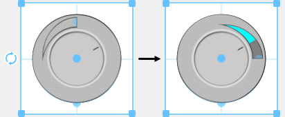
Custom radio knob with the foreground in its default orientation (left), and with the foreground rotated ninety degrees (right)

Change scale direction for customizable dashboard blocks

Several dashboard blocks in the Customizable Blocks library allow you to specify the direction for the scale:

Lamp block in Customizable Blocks library supports specifying state values as ranges

The Lamp block connects to a signal and displays a color that reflects the value of the connected signal. In previous releases, you could only specify a discrete value for each state and design a Lamp block that indicated when the connected signal had that specific value. Starting in R2022a, you can specify each state value as a range and design a Lamp block that indicates when value of the connected signal is within each range.

View and edit each state for customizable Lamp block in design mode

Starting in R2022a, you can view and edit each state for the customizable Lamp block in design mode, and you can modify more aspects of the block appearance for each state. For example, you can now design a lamp that uses a different icon for each state.
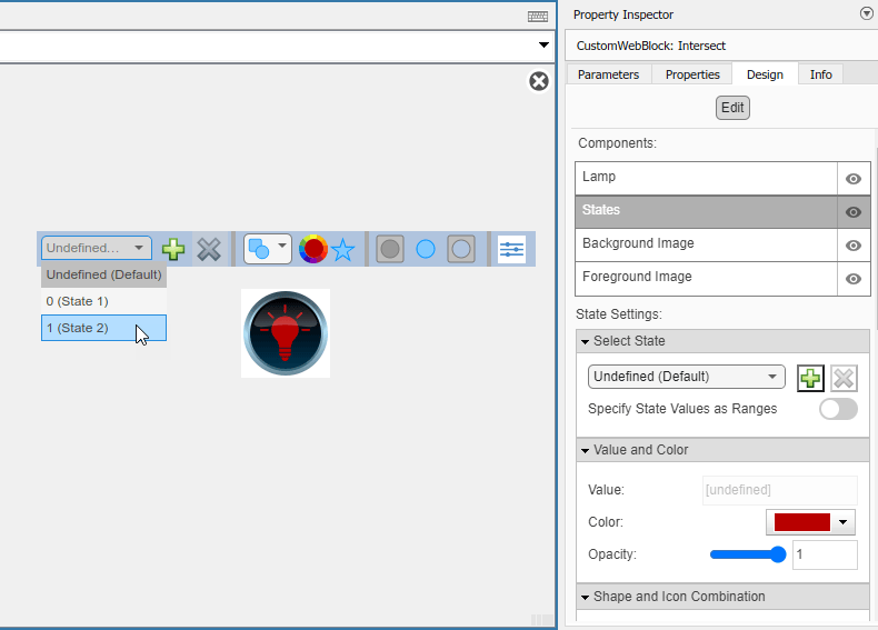
Customizable Lamp block in design mode with the Design tab of the Property Inspector visible.

Change opacity of state colors for customizable Lamp block

For the customizable Lamp block, you can now change the opacity of the color that you set for a state.

From Spreadsheet block Range Selection tool updates

Range Selection from the Range parameter of the From Spreadsheet block has these changes:

  • The interface has an updated toolstrip in the top right. There is no longer a Help icon for this interface. Instead, see the Range parameter documentation.

  • The Range field is now Selection/History.

  • If you do not specify a range in the Range parameter, Range Selection now displays all cell entries as selected.

Unit Conversion block now accepts multidimensional signals

The Unit Conversion block now accepts multidimensional signals at the block input port.

Simulink.ImageType data type for image signals

In R2022a, you can now use the Computer Vision Toolbox™ to specify an image of the Simulink.ImageType (Computer Vision Toolbox) data type and simulate the model. Specify this data type for signals and other data in the model. The Simulink.ImageType data type is an encapsulated object that defines an image by using fixed meta-attributes specific to this data type.

The blocks listed in this table support simulation and code generation of a Simulink.ImageType object.

Block LibraryBlock Name
Sources
  • Ground

  • Inport

  • Outport

Signal Routing
  • Goto

  • From

  • Data Store Read

  • Data Store Write

  • Data Store Memory

  • Switch

  • Multiport Switch

  • Merge

  • Variant Source

  • Variant Merge (internal block added during code generation)

  • Mux

  • Demux

  • Vector Concatenate, Matrix Concatenate

  • Selector

Sink
  • Terminator

  • To Workspace (simulation only)

  • Record (simulation only)

Ports & Subsystems
  • Subsystem, Atomic Subsystem, CodeReuse Subsystem

  • Enabled Subsystem

  • Triggered Subsystem

  • Function-Call Subsystem

  • If

  • Switch Case

  • Resettable Subsystem

  • For Iterator Subsystem

  • Model

Discrete
  • Unit Delay

Signal Attributes
  • Signal Conversion

  • Signal Specification

User-Defined Functions
  • Initialize Function, Reset Function, and Terminate Function

  • Simulink Function block with side I/O and arguments

For more information, see the Computer Vision with Simulink: Specify image data type in Simulink model (Computer Vision Toolbox) release note.

Discrete PID Controller Blocks: Improve execution time of generated code

By default, the Discrete PID Controller and Discrete PID Controller (2DOF) blocks take the integral gain as input and multiply it by the sample time internally as a part of performing the integration. You can now configure the blocks to accept the integral gain premultiplied with the sample time as an input. Doing so improves the execution time of the generated code. Therefore, when you have limited processing power, enable the Use I*Ts parameter and specify the Integral parameter value as the integral gain multiplied by the controller sample time.
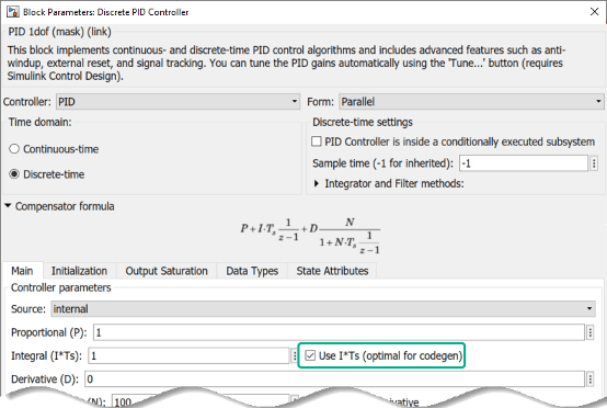
Discrete PID Controller block parameters.

Additionally, if your controller uses an anti-windup mechanism, enhancements to the clamping method also reduce the execution time of the generated code.

 Functionality being removed or changed

To Workspace block logging enhancements

Behavior change

Starting in R2022a, the To Workspace block supports:

  • Logging an array of buses.

  • Logging signals with string and half data types.

  • Logging int64 and uint64 data using built-in data types.

  • Using the Timeseries format in rapid accelerator simulations.

  • Using the Timeseries format for To Workspace blocks inside For-Each subsystems.

Data logged using To Workspace blocks also streams to the Simulation Data Inspector during simulation.

 Compatibility Considerations
  • In prior releases, the To Workspace block logged int64 and uint64 as a fi object when a license for Fixed-Point Designer™ was available and as double data when the license was not available. Starting in R2022a, the To Workspace block always logs int64 and uint64 data using the built-in data types.

  • In prior releases, data logged using the To Workspace block only logged to the workspace and was overwritten for each simulation unless you changed the logging variable names or saved the results yourself.

    Starting in R2022a, data logged using To Workspace blocks logs to the Simulation Data Inspector as well as the workspace. When you run multiple simulations in a single MATLAB session, the Simulation Data Inspector automatically retains results from each simulation so you can analyze the results together. Starting in R2022a, because data logged using To Workspace blocks streams to the Simulation Data Inspector, this data is also retained.

    Logging large amounts of data or running many simulations can produce large amounts of data that fill up disk space. To learn how to control the amount of data retained in the Simulation Data Inspector, see Limit the Size of Logged Data.

Access to Simulink Scope through Handle Graphics API will be removed

Still runs

The underlying graphics of the Simulink Scope block will change in a future release. Once that happens, you will not be able to access or modify the Simulink Scope block through the handle graphics API.

Update any undocumented use of handle graphics APIs that access the Scope window.

Floating Signal Selection will be removed

Still runs

The floating signal selection feature (Lock button used to enable the selection of multiple signals) in the Floating Scope block will be removed in a future release. To connect signals to your floating scope, use the existing signal selector (signal selector icon on floating scope) instead. For more details, see Add Floating Scope Block to Model and Connect Signals.

Ability to dock Scopes to MATLAB desktop will be removed

Still runs

The ability to dock the Simulink Scope, Time Scope (DSP System Toolbox), Floating Scope and Scope Viewer to the MATLAB desktop will be removed in a future release.

SampleInput parameter will be removed

Still runs

The SampleInput parameter of the Simulink Scope, Time Scope (DSP System Toolbox), Floating Scope and Scope Viewer (currently accessed through the command line API) will be removed in a future release.

Connection to Hardware

Support added for 64-bit Android applications

Use the Simulink Support Package for Android Devices to build and deploy Android applications on your device that supports 64-bit Android application packages (APK). You can use the Android Device (64-bit) option under Hardware board in the Configuration Parameters dialog box to generate a 64-bit APK for your Android application. Alternatively, you can use the Create 64 bit library as well option under Android Device hardware board to generate a 32-bit and a 64-bit APK for your Android application.

Support added to integrate algorithm to existing Android application

Use the Simulink Support Package for Android Devices to integrate an algorithm developed in Simulink into an existing Android application using Android Studio. Use the Create Android library module for Simulink model option in the Configuration Parameters dialog box to create a library module for the Simulink model that can be further integrated with the code of an existing Android application. This option is available under App options in the Configuration Parameters dialog box for both Android Device and Android Device (64 bit) hardware options.

Better visual display and auto rotate applications on Android devices

Starting R2022a, you can now navigate easily through the tabs of an application deployed on your Android device. If your model contains a Camera or Scope block from Simulink Support Package for Android Devices and is deployed on your Android device, you can automatically rotate the application with the Android device. Previously, you could not automatically rotate the application.

Support added for Arduino compatible ESP32-WROOM boards

The Simulink Support Package for Arduino Hardware now supports deploying Simulink models on the ESP32-WROOM boards. The ESP32-WROOM (Arduino Compatible) option has been added to the Hardware board drop-down list in the Configuration Parameters dialog box. Starting R2022b, you can use these ESP32-WROOM boards:

  • ESP32-WROOM-DevKitV1(30 pin)

  • ESP32-WROOM-DevKitV1(36 pin)

  • ESP32-WROOM-DevKitC(38 pin)

The support package also provides real-time execution profiling for the Simulink models deployed on the ESP32-WROOM boards. You can use these blocks from the support package library with the ESP32-WROOM boards.

Digital InputProtocol EncoderBNO055 IMU SensorLSM6DS0 IMU Sensor
Digital OutputProtocol DecoderTachometerLSM6DSR IMU Sensor
Analog InputExternal InterruptAPDS9960 SensorLSM303C IMU Sensor
Analog OutputWiFi TCP/IP ReceiveMPU9250 IMU SensorLPS22HB IMU Sensor
PWMWiFi TCP/IP SendMPU6050 IMU SensorHTS221 Humidity Sensor
Serial ReceiveWiFi UDP ReceiveLSM9DS1 IMU SensorEncoder
Serial TransmitWiFi UDP SendLSM6DS3 IMU SensorADXL34x Accelerometer
I2C WriteWiFi ThingSpeak ReadLSM6DS3H IMU SensorCCS811 Air Quality Sensor
I2C ReadWiFi ThingSpeak WriteLSM6DSL IMU SensorICM20948 IMU Sensor
SPI Write ReadUltrasonic SensorLSM6DSM IMU SensorVL530x Time of Flight Sensor

Hardware support extended for real-time execution of generated code on Arduino boards

The Simulink Support Package for Arduino Hardware now provides real-time execution profiling for the Simulink models deployed on these Arduino boards:

  • Arduino Uno

  • Arduino Mega ADK

  • Arduino Mega 2560

  • Arduino Leonardo

Previously, real-time execution profiling was supported only on ARM architecture-based Arduino boards.

Select serial communication port for external and PIL modes on Arduino boards

For Simulink Support Package for Arduino Hardware, you can now select any serial communication port on your Arduino board to run the models in either external (Monitor & Tune) or PIL modes. Previously, you could select only serial port 0 on your Arduino board.

Support extended for executing multitasking models for Arduino Nano 33 BLE Sense board

Prior to R2022a, using the Simulink Support Package for Arduino Hardware for executing and deploying multitasking models on Arduino Nano 33 BLE Sense board was not supported.

Starting in R2022a, you can deploy models containing blocks running at different sample rates on your Arduino Nano 33 BLE Sense boards.

Control pan and tilt motions using PCA9685-based PWM driver

With the addition of the Pan Tilt Hat block to the Raspberry Pi Blockset, you can now control the pan and tilt motions of the pan-tilt hardware using the PCA9685 kernel module.

Adjust and set video and camera parameters using V4L2 Video Capture block in Raspberry Pi

Using the V4L2 Video Capture block from Raspberry Pi Blockset, you can now adjust various parameters for an input video such as brightness, saturation, contrast, sharpness, and flip along vertical and horizontal axes. You can also adjust various parameters of your camera such as pan and tilt angles, zoom-in and zoom-out, and enable manual focus using the block.

Improved build and deployment speeds for Raspberry Pi Blockset

Before R2022a, in the Raspberry Pi Blockset, the generated code and the driver source code were compiled sequentially. From R2022a, the code is compiled in parallel, thus reducing the time taken to build models. You can change this default behavior and choose to build the model sequentially by clearing the Enable parallel build parameter under Build options in the Configuration Parameters dialog box.

Manually set XCP-based polling time for Simulink model running on Raspberry Pi

You can now manually set the XCP-based polling time for Simulink models that contain blocks from the Raspberry Pi Blockset running in the external mode (Monitor & Tune). A new parameter, Set XCP target polling time, has been added in the Configuration Parameters dialog box. Previously, the polling time for Simulink models running in external mode was calculated automatically.

Higher data acquisition rates using Connected I/O with Arduino boards

The Simulink Support Package for Arduino Hardware now supports higher data acquisition rates for sensor/peripheral blocks with Arduino boards using Connected I/O. In the Connected I/O mode, use the sensor/peripheral blocks in the model, enable Simulation Pacing, and then set the Simulation time per wall clock second to 1 for a higher data acquisition rate.

Read distance to target object using VL53L0X sensor

The Simulink Support Package for Arduino Hardware now supports interfacing the VL53L0X sensor with Arduino hardware. You can use the new VL503L0X Time Of Flight Sensor block to measure the distance to a target object for a complete field of view. The block also provides the option to select one of four ranging modes based on your requirements.

Read linear acceleration, angular velocity, magnetic field, and temperature using ICM-20948 sensor

The Simulink Support Package for Arduino Hardware now supports interfacing the ICM-20948 nine-axis sensor with Arduino hardware. You can use the new ICM20948 IMU Sensor block to measure linear acceleration, angular velocity, and magnetic field along the X, Y and Z-axes, and to measure temperature. The block also provides the option to generate the data ready interrupt.

Read eCO2 and eTVOC using CCS811 sensor

The Simulink Support Package for Arduino Hardware now supports interfacing the CCS811 sensor with Arduino hardware. You can use the new CCS811 Air Quality Sensor block to measure the equivalent CO2 (eCO2) and the equivalent total volatile organic compound concentration (eTVOC) for indoor air quality monitoring. The block also provides the option to use temperature and humidity data to enable compensation (either by specifying the humidity and temperature values or by interfacing CCS811 with an external sensor).

Read linear acceleration using ADXL34x family of accelerometers

The Simulink Support Package for Arduino Hardware now supports interfacing the ADXL34x family of accelerometers (ADXL343, ADXL344, ADXL345, and ADXL346) with Arduino hardware. You can use the new ADXL34x Accelerometer block to measure linear acceleration along the X, Y and Z-axes. The block also provides the option to enable the data ready interrupt.

MATLAB Function Blocks

Cell Array Type for Non-Tunable Parameters

In MATLAB Function blocks, you can use cell arrays as non-tunable parameter data. To use cell-arrays as non-tunable parameters in your MATLAB Function block, see Configure MATLAB Function Block Parameter Variables and ensure that the Tunable option is cleared.

 Variable Size property applies only to output variables

Starting in R2022a, the Variable size property only applies to MATLAB Function block variables with the Scope property set to Output. Input variables now inherit size variability from their corresponding signals. Prior to R2022a, this property could also be applied to MATLAB Function block variables with Scope set to Input. Updating a model created in a previous release disables this property for input variables.

You can still specify the property for variables used in both the input and output of the function declaration statement. For example, if you define the function y = myFunction(y), the variable y has this property.

Symbols pane replaces Ports and Data Manager

In R2022a, the Ports and Data Manager has been removed. To manage variables, function call outputs, and input triggers in MATLAB Function blocks, use the Symbols pane and the Property Inspector.
This image shows the Symbols pane as it appears in a new MATLAB Function block.

For more information on managing variables, function call outputs, and input triggers with the Symbols pane and Property Inspector, see Create and Define MATLAB Function Block Variables, Manage Function Call Outputs of a MATLAB Function Block, and Manage the Input Trigger of a MATLAB Function Block.

New Code Generation Readiness Tool: View more information and navigate through readiness results more easily

In R2022a, the Code Generation Readiness Tool has a new user interface, more information, additional functionality, and improved navigation. In addition, you can now use the Code Generation Readiness Tool in MATLAB Online.
Screenshot of the code generation readiness tool with sample code and analysis results.

In addition to the existing functionalities, you can now:

  • View your MATLAB code inside the Code Generation Readiness Tool. When you select an issue, the part of your MATLAB code that caused this issue gets highlighted.

  • Group the readiness results either by issue or by file.

  • Select the language that the code generation readiness analysis uses.

  • Refresh the code generation readiness analysis if you updated your MATLAB code.

See Check Code Using the Code Generation Readiness Tool and coder.screener.

coder.ScreenerInfo object: Access code generation readiness information programmatically

In R2022a, you can export the code generation readiness information about your MATLAB code to a variable in your base workspace. This variable contains a coder.ScreenerInfo object whose properties contain information about:

  • MATLAB files analyzed by the Code Generation Readiness Tool

  • Code generation readiness messages

  • Calls to functions not supported for code generation

To export code generation readiness information about your the files foo1.m, foo2.m, and foo3.mlx to the variable info in your base workspace, execute this function call:

info = coder.screener('foo1.m','foo2.m','foo3.mlx')

You can also export the entire report to a MATLAB string by executing the object function textReport:

reportString = textReport(info)

See:

Code generation for more toolbox functions

In R2022a, you can generate code for many additional toolbox functions and objects. For a list of all functions and objects that are supported for code generation, see:

Modeling Guidelines

 High-Integrity Systems Modeling Checks: Improve quality and compliance with guidelines ​​​​

In R2022a, you can use these high-integrity modeling guidelines:

High-Integrity GuidelineEquivalent Model Advisor Check
hisl_0075: Usage of library linksCheck for disabled and parameterized library links
hisl_0101: Avoid operations that result in dead logic to improve code complianceCheck for unreachable and dead code

 Compatibility Considerations

These guidelines were removed in R2022a:

High-Integrity GuidelineCorresponding Modeling Check

hisf_0003: Usage of bitwise operations

Use hisl_0019: Usage of bitwise operations.

Check usage of bitwise operations in Stateflow charts.
hisf_0009: Strong data typing (Simulink and Stateflow boundary)Check for Strong Data Typing with Simulink I/O

S-Functions

Programmatically configure S-functions using the S-Function Builder block

Starting in R2022a, you can use functions to configure an S-Function Builder block to build an S-function for your model. You can use the functions to:

  • Configure settings, including build options and options to support model coverage and design verification.

  • Specify user code for the S-function methods.

  • Compile the S-function source and MEX.

For more information, see Implement C/C++ Code Using S-Function Builder.

 Functionality being removed or changed

Level-1 Fortran S-function will be removed in a future release

Still runs

Level-1 Fortran S-functions will be removed in a future release. Use Level-2 Fortran S-functions instead. To learn more about Level-2 Fortran S-functions, see Create Level-2 Fortran S-Functions and explore the sfcndemo_atmos example.